Welding Inverter Design Calculator
 Wired White v1
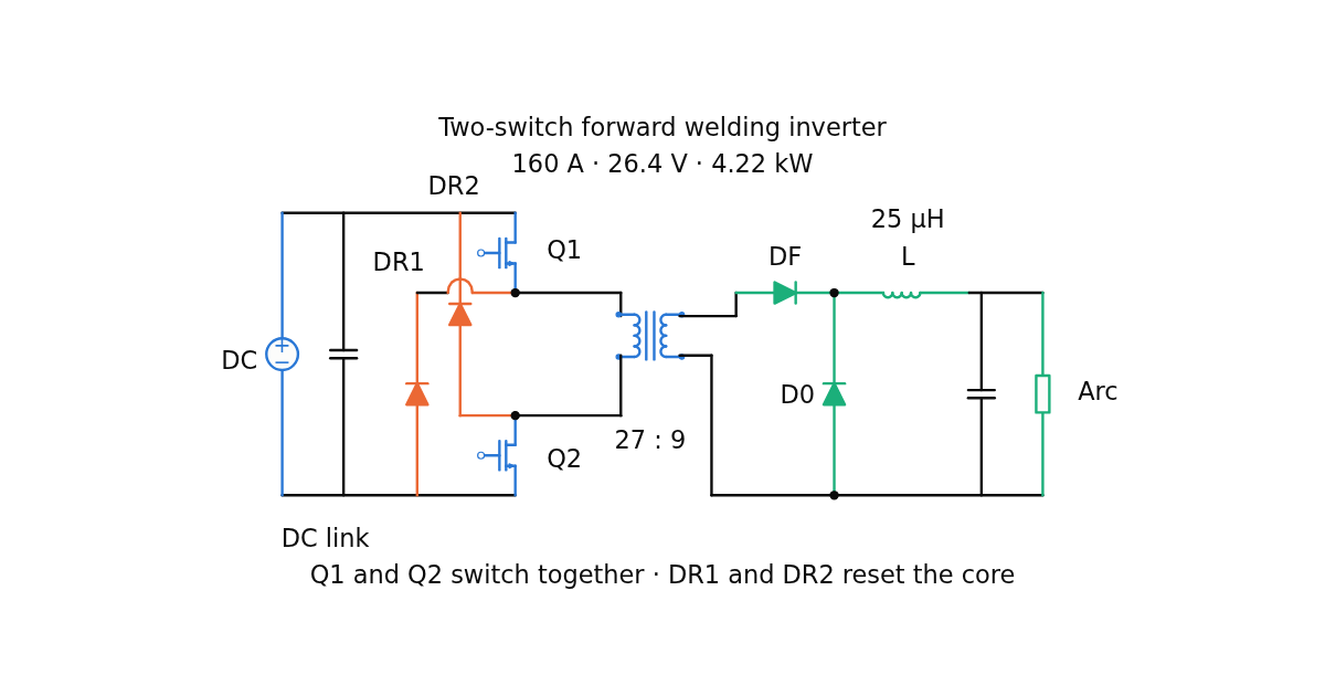
Size a two-switch forward welding inverter: transformer turns and copper, output choke, switch currents and losses, mains demand, and the arc load characteristic.
Wired White v1 Size a two-switch forward welding inverter: transformer turns and copper, output choke, switch currents and losses, mains demand, and the arc load characteristic.
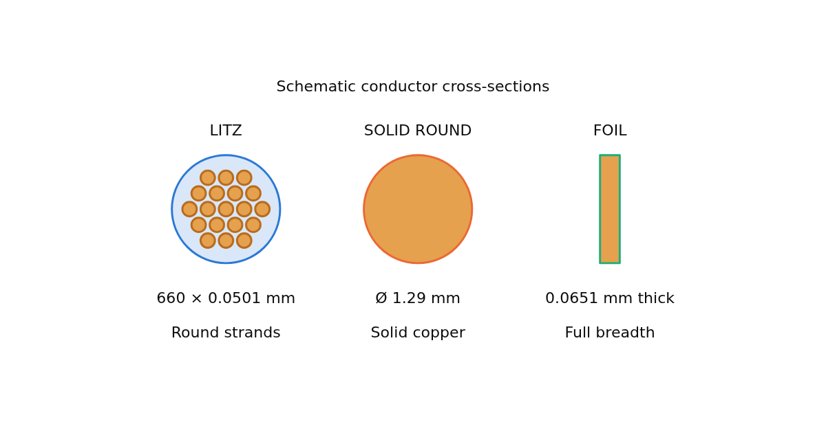
Wired White v1 Find a low-loss litz strand diameter and count for your winding window. Compare equal-copper solid wire and foil, including skin effect, proximity effect and current harmonics.
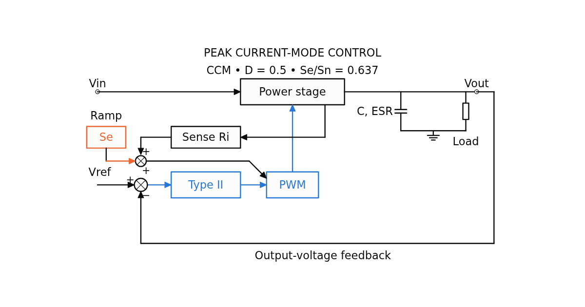
Wired White v1 Size the slope compensation and design a Type-II voltage loop for CCM buck, boost and flyback converters. Inspect sampled-data peaking, all gain crossings, Bode plots and a linear load-step estimate.
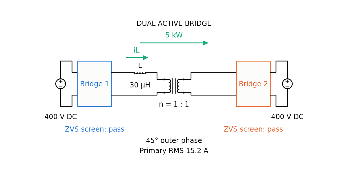
Wired White v1 Size DAB inductance and phase shift, find both bridges’ ZVS limits, and calculate RMS and peak currents. Compare SPS, EPS, DPS and TPS with animated waveforms.
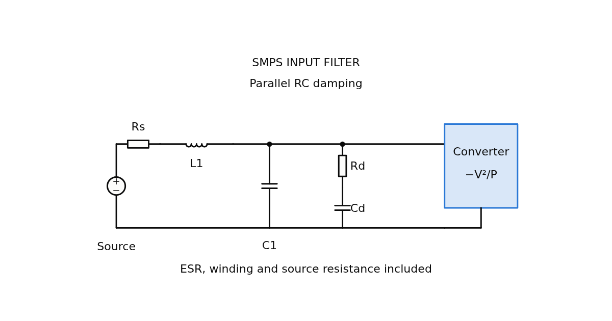
Wired White v1 Check whether an LC input filter threatens converter stability. Compare RC and RL damping, two-stage filters, ripple attenuation, losses and small-signal transients.
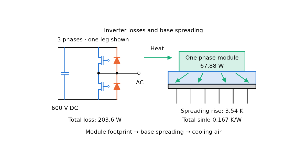
Wired White v1 Estimate IGBT inverter losses and heatsink requirements including base spreading. Compare footprint and thickness effects on resistance and hot-spot temperature.
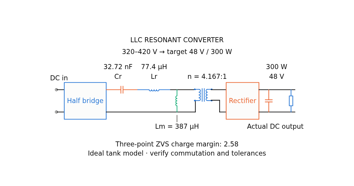
Wired White v1 Size an LLC tank, compare FHA with exact PO/NP gain, and check ZVS charge margin and component stress for half-bridge or full-bridge operation.
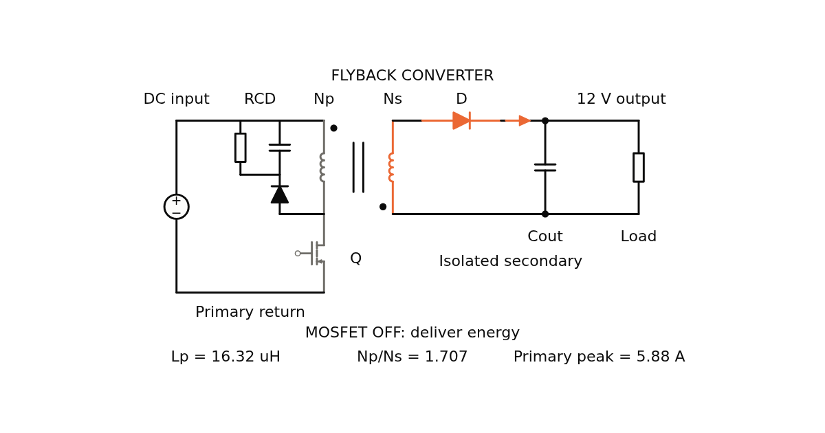
Wired White v1 Size or check a flyback transformer in DCM or CCM. Calculate inductance, turns ratio, peak and RMS currents, device voltage stress, winding estimates and an RCD clamp.
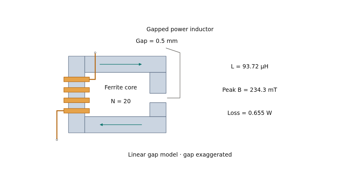
Wired White v1 Size a gapped ferrite inductor and check peak flux, copper loss and iGSE core loss. Compare air-gap and ripple-duty tradeoffs with published ferrite baselines.
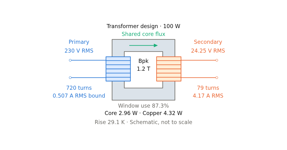
Wired White v1 Size mains and ferrite bridge transformers with turns per volt, peak flux, window fill, copper and core losses, and temperature rise. Includes traceable loss models and winding checks.
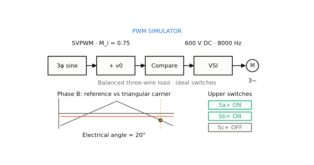
Wired White v1 Compare SPWM, SVPWM, THIPWM and DPWM0–3. Animate the space-vector hexagon, inspect seven-segment switching and dwell times, and compare current ripple and relative switching loss.
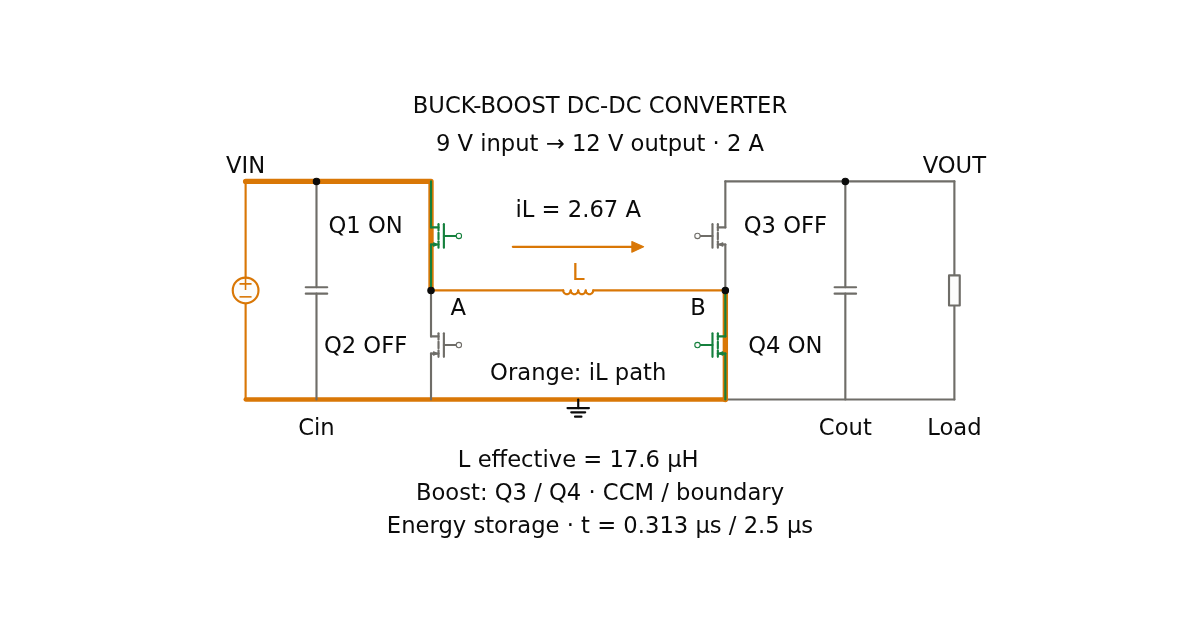
Wired White v1 Design a non-inverting four-switch buck-boost power stage. Check CCM/DCM operation, inductor and capacitor sizing, RMS and peak stresses, and optional iGSE core loss.
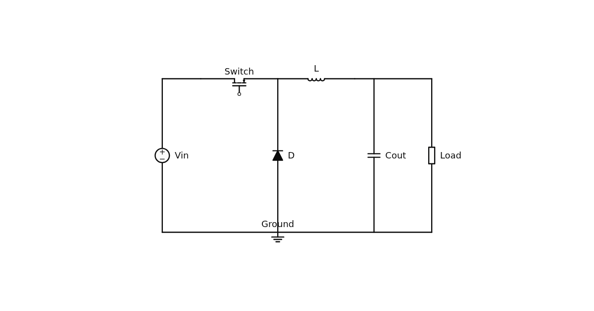
Wired White v1 Size the inductor and output capacitor of a continuous-conduction buck converter and inspect its triangular inductor current.






Please confirm you want to block this member.
You will no longer be able to:
Please allow a few minutes for this process to complete.