Electric Drivetrain Modeling & Simulation Services
Modeling and simulation of electric drivetrains, electric machines, inverters, power converters and propulsion systems — including PMSM, ASM and SynRM.
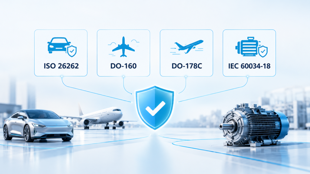
Trust ISO 26262 · DO-160 · DO-178C · IEC 60034-18
Electric Drivetrain Engineering Services
The job is to build models that match the hardware, and to find the places where the current ones don’t.
Here is what we cover:
01
System architecture and requirement breakdown
02
Machine and converter modeling
03
Control and thermal models
04
Derating logic
05
Loss maps
06
Correlation against measured data
We can help and improve existing customer’s models or we can create a new model from the scratch. Models are parametrized, documented, and handed over so your team can run and modify them without us. When a requirement changes, the model changes with it, and everyone works from the same numbers.
We get involved at whatever stage the project is at, and we start by finding where the model diverges from reality.
Service
⚙️ Drivetrain System Modeling
🧲 Electric Machine Modeling
⚡ Inverter & Power Converter Modeling
🎛️ Motor Control Modeling
🌡️ Thermal Drivetrain Modeling
📈 Loss & Efficiency Modeling
🚦 Derating & Operating Limits
💻 Model-Based Software Development (MIL/SIL/HIL, FuSA)
🔗 Supplier & Component Sourcing Support
🛠️ Mechanical & System-Level Engineering
🧪 Validation & Test Correlation
- Full drivetrain model — source, converter, machine, transmission, load
- Efficiency, thermal duty cycle, torque response, fault behavior
- Feasibility studies and requirement breakdown — from vehicle level to components
- Model delivered parametrized and documented
The model is built once and used across the studies your project needs. Your team runs it, modifies it, and extends it without us.
- PMSM (interior and surface-mounted)
- DC motors
- Induction machines (ASM)
- Synchronous reluctance machines (SynRM)
Models are built to the fidelity of the question — dq-frame with saturation and temperature-dependent parameters for PMSM, slip-dependent rotor parameters for induction, saliency behavior for SynRM. Where the machine doesn’t exist yet, parameters come from datasheets, FEA, or supplier data, with a clear note on what is measured and what is estimated.
- Averaged models for system studies
- Switching-level models for loss, EMI, and current ripple analysis — with dead time, modulation strategy, and DC-link dynamics included
We also match the converter to the machine. Switching frequency, current limits, voltage limit ellipse, and thermal derating of the power stage determine what the machine can deliver, and are included in the model.
- Field Oriented Control (FOC) / vector control
- Torque, speed, and power control loops
- Sensorless control techniques
Control algorithms are tested against the machine and converter models or using Hardware-in-the-loop (HIL) testing before they run on hardware — loop tuning, field weakening, and observer design included.
- Thermal model creation and parametrization
- S1/S3 duty cycles, rated and peak curves
- Steady-state and transient simulation
- Cooling path modeling for machine and converter
- Parametrization against measurement or FEA
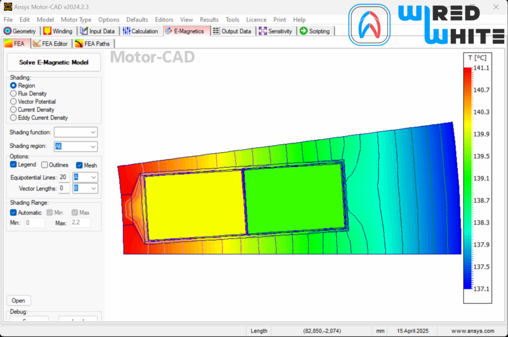
We build thermal models of the machine, the converter, and the cooling path, parametrized against measurement or FEA where data exists. The models cover continuous and peak operation, so the limits you see are the limits the hardware will hold.
- Motor loss determination — iron, copper, magnet, friction
- Proximity and skin effect in winding AC resistance
- Efficiency maps across torque, speed, and temperature
- Curve fitting and model optimization
Loss models are parametrized against measurement and used to build efficiency maps under real operating conditions, not just at nominal temperature. The maps feed directly into the system model, so efficiency figures stay consistent across studies.
- Rotor and stator temperature derating
- Inverter coolant temperature derating
- HV AC/DC current (I²t) derating
- IGBT temperature delta derating
- Inverter PWM frequency and NTC temperature derating
Derating functions are modeled as part of the control and thermal models, so the limits you see in simulation are the limits the hardware will enforce.
- MIL, SIL, and HIL workflows
- Functional safety (FuSA)-compliant software
- Software/component level requirement breakdown
- Unit, integration, and validation tests
- Software project management
Software is developed against the same models used for system simulation, so control logic, safety functions, and plant behavior stay aligned through the development cycle.
- Supplier sourcing and prototype purchasing
- RFI and RFQ process organization and review
- Feasibility review of third-party designs
- Prototype manufacturing coordination
We support the sourcing side of the project, from identifying suppliers to reviewing what they deliver against your requirements.
- CAD design and drawing creation of motor components
- Mechanical integration into the overall system
- Stress analysis — FEM calculations
- Project management, product owner, scrum master support
CAD, FEM, CFD, and project management sit alongside the modeling team, so mechanical and system-level decisions are made on the same data as the simulation.
- Test bench support — Sample A/B/C/D, prototype, and type testing
- Design Validation Plans
- Correlation of simulation results against measured data
- Compliance with ISO 26262, DO-160, DO-178C, IEC 60034-18
Validation closes the loop between model and hardware. Where measurements diverge from simulation, the model is refined until the two agree.
Accelerate your roadmap and avoid costly rework with proven engineering practices.
Engineering Challenges We Solve
🎯 System-level modeling is missing or inaccurate, so simulated torque and efficiency do not match prototype measurements
🎯 Machine and converter are specified separately and parametrized from different sources — the mismatches only appear later
🎯 Derating strategies are defined late and often based on datasheet limits rather than thermal models
🎯 Performance and efficiency calculations do not reflect real operating conditions, so thermal and derating decisions are made on the wrong numbers
🎯 Thermal models are incomplete, and the test bench finds what simulation missed
🎯 Test and validation costs climb because the model was never correlated against measured data
We build the model first, parametrize it against measurement, and let it carry requirements, derating, thermal limits, and validation through the project.
Electric Drivetrain Applications & Voltage Classes
- 🔌 DC Voltage Levels:
- ⚡ Power Ranges:
- 🚗 Applications Covered:
- 12–48V: conventional systems
- 48V: hybrid & low power
- 400V: traction drives, industrial machinery
- 800V: eBus, eTruck, mining
- 1200V–2400V: aerospace
- 5–25kW: starter/generator/mild hybrid
- 100–300kW: electric/hybrid vehicles
- 150–600kW: eBus, eTruck, mining
- 650–1000kW: racing, aerospace
- 10MW: wind power, energy applications
- BEV, EREV, PHEV, HEV
- Electric Busses & Trucks (traction, axial drive)
- Heavy-duty trucks & machinery
- eVTOL, hybrid electric aviation
- Mining & industrial applications
Modeling and Simulation Workflow
-
01 Requirements & System Definition
What needs to be calculated, at what fidelity, and under which operating conditions and constraints
-
02 Model Development
System, machine, converter, and control models are built and connected
-
03 Parameter Identification
Parameters are determined from datasheets, FEA, supplier data, or measurement, depending on what is available
-
04 Simulation & Optimization
defined operating scenarios are run, and model or system parameters are adjusted against project targets
-
05 Validation Against Measurements
simulation results are compared with test bench data, and the model is refined where the two differ
Tools, Technologies & Collaboration
MATLAB & Simulink
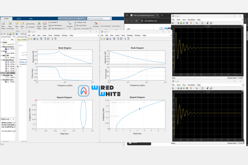
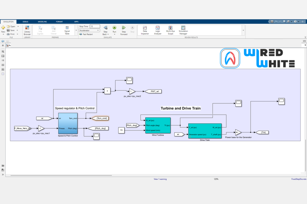
System-level drivetrain models, control algorithms, and plant models are built and tested in Simulink before they run on hardware. Model-based development, MIL/SIL workflows, and code generation for target ECUs are handled in the same environment.
Ansys Maxwell & Motor-CAD
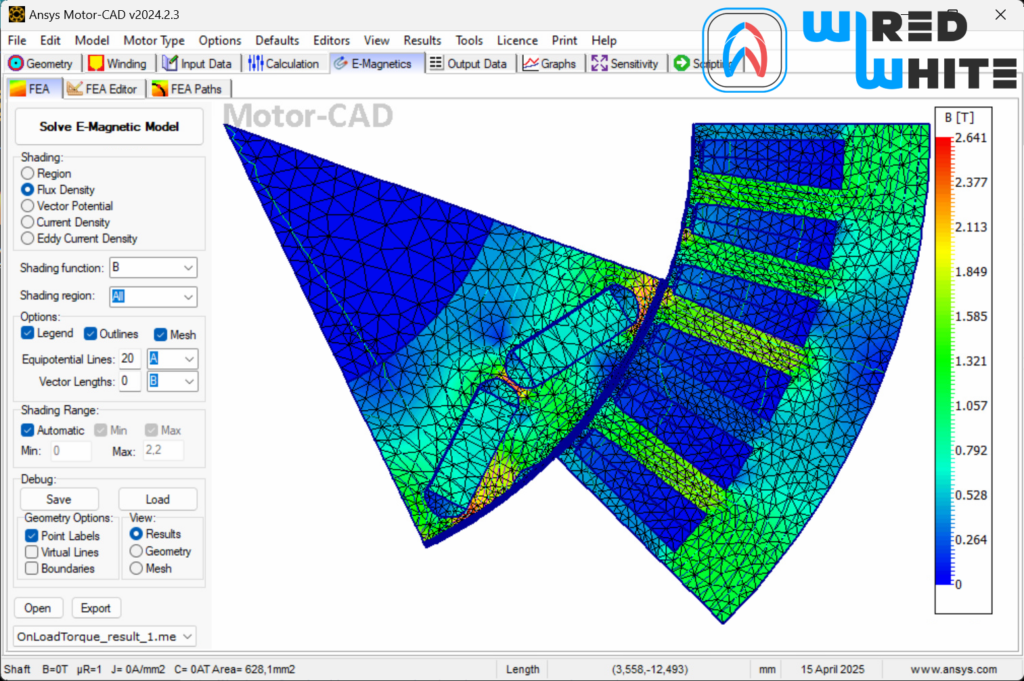
Electromagnetic design and analysis of electric machines. Maxwell handles 2D or 3D FEM for flux, inductance, and loss calculation. Motor-CAD covers thermal and electromagnetic analysis of e-motor systems, including continuous and peak operation.

Real-Time Simulation & HIL Testing
Control algorithms and plant models are moved to real-time targets for hardware-in-the-loop testing. ECU interfaces, sensor and actuator behavior, and fault response are validated before the full system is assembled.

Speedgoat, dSPACE, CANape, INCA & TargetLink
ECU calibration, measurement, code generation, and real-time validation. These tools connect the simulation model to the physical ECU — parameter tuning, signal measurement, production code generation.

WiredWhite Collaboration Platform
Project-specific workspaces, task boards, video conferencing with screen sharing and recording, and structured document handling. The platform keeps project communication, files, and decisions in one place.
Standards & Engineering Process
Functional Safety & Compliance
- ISO 26262 — functional safety for road vehicles
- DO-160 — environmental conditions and test procedures for airborne equipment
- DO-178C — software considerations in airborne systems
- IEC 60034-18 — insulation systems for rotating electrical machines
Compliance is built into the model and software development cycle, not checked at the end. Safety requirements are traced from system level to software and hardware, and validation evidence is produced against the relevant standard.
Development Processes
- ASPICE — automotive software process improvement
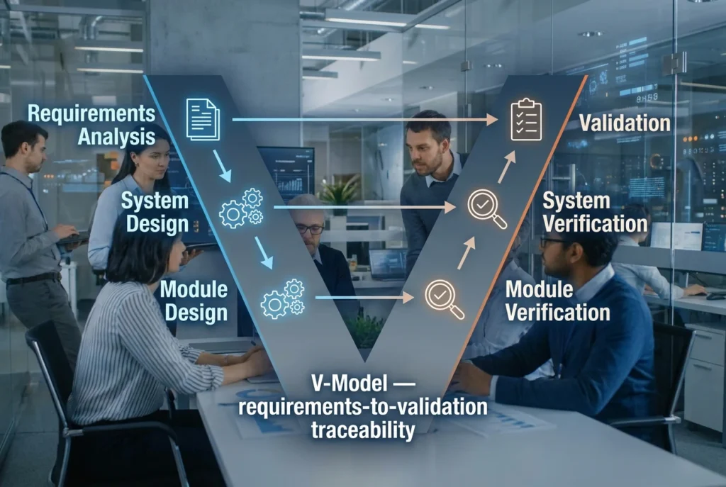
- V-Model — requirements-to-validation traceability
- Agile, Scrum, Kanban — iterative development with sprint planning
- Lean, Kaizen, Six Sigma — process efficiency and defect reduction
Processes are selected to fit the project, not applied as a template. A safety-critical development runs on V-Model and ASPICE; a prototype or research project runs on shorter cycles with the same traceability.
Why WiredWhite is the Perfect Engineering Partner for You
⏱ 15+ Years
industry experience
👨 1000+
networked engineering professionals
🔄 Integrated
project collaboration tools
✅ 100%
Proficient in advanced engineering tools
We Are Supporting Businesses, Executives, and Innovators Worldwide
Freelance Agencies
Teams of Engineers
Start-ups
Companies
Motor Solutions for Every Business

Sara, Account-ManagerinSOLCOM GmbH

Katharina, Team Lead Rolling Stockemagine GmbH

Martin, Domain Lead Electrical SystemsALSTOM Drives GmbH

Stefanie, Service Delivery Managerinemagine GmbH


Theresa, Proficient Key Account ManagerSOLCOM GmbH

Max, Technical Project Lead E-DrivesNidec Motors & Actuators (Germany) GmbH

Franziska, Principal ConsultantAmoria Bond GmbH
Seán, Chief Executive OfficerGrip Factory Munich GmbH

- Free consultation call
- Contact form
Partner with Us for Your Electric Drivetrain Modeling & Simulation Project
Speak directly with our drivetrain experts to explore how we can help you model, simulate, and validate electric propulsion systems — with speed, precision, and full standards compliance.
Let’s move your ideas forward.
Explore All Our Business Services
We offer full-cycle engineering services ranging from small consulting projects to extensive R&D projects, where we support throughout the entire product development process.