

Simulation Under Grid Faults in Wind Power Systems in MATLAB

Author: Waqas Javaid
Abstract
The increasing penetration of wind energy into modern electrical grids has created a strong requirement for accurate dynamic analysis of wind turbine behavior during abnormal grid conditions. Unlike conventional generation systems, wind turbines are highly dependent on power electronic converters and advanced control strategies, making them sensitive to voltage disturbances, frequency variations, and grid impedance changes. Therefore, simplified steady-state models are insufficient for evaluating the real response of wind power systems during grid faults.
This paper presents a dynamic simulation-based investigation of grid fault conditions in wind power systems, focusing on practical engineering analysis workflows for doubly fed induction generator (DFIG) and full-converter wind turbines. Different disturbance scenarios, including voltage dips, balanced and unbalanced faults, frequency deviations, and weak grid conditions, are analyzed through time-domain simulation. The study explains how fault events influence converter operation, rotor and stator currents, DC-link voltage behavior, phase-locked loop (PLL) stability, fault ride-through (FRT) capability, and electromechanical stress.
Dynamic simulation enables engineers to identify instability mechanisms that cannot be observed using steady-state or phasor-only models. The results of fault simulation provide essential information for converter protection design, controller tuning, grid-code compliance verification, and improvement of renewable energy integration reliability.
1. Introduction
The global transition toward renewable energy has significantly increased the contribution of wind power systems in electrical networks. Modern wind turbines are no longer simple electromechanical machines; they are integrated systems consisting of aerodynamic components, generators, power electronic converters, digital controllers, protection systems, and grid interface mechanisms. This complexity allows wind turbines to provide advanced grid-support functions, but it also introduces additional sensitivity to grid disturbances.
Grid faults are unavoidable events in real power systems. Transmission failures, short circuits, sudden load changes, and variations in grid strength can create severe electrical stress on wind turbines. During such events, wind turbines must remain connected and support grid recovery instead of disconnecting immediately. Therefore, modern grid codes require wind turbines to satisfy fault ride-through requirements and maintain stable operation during abnormal conditions [1].
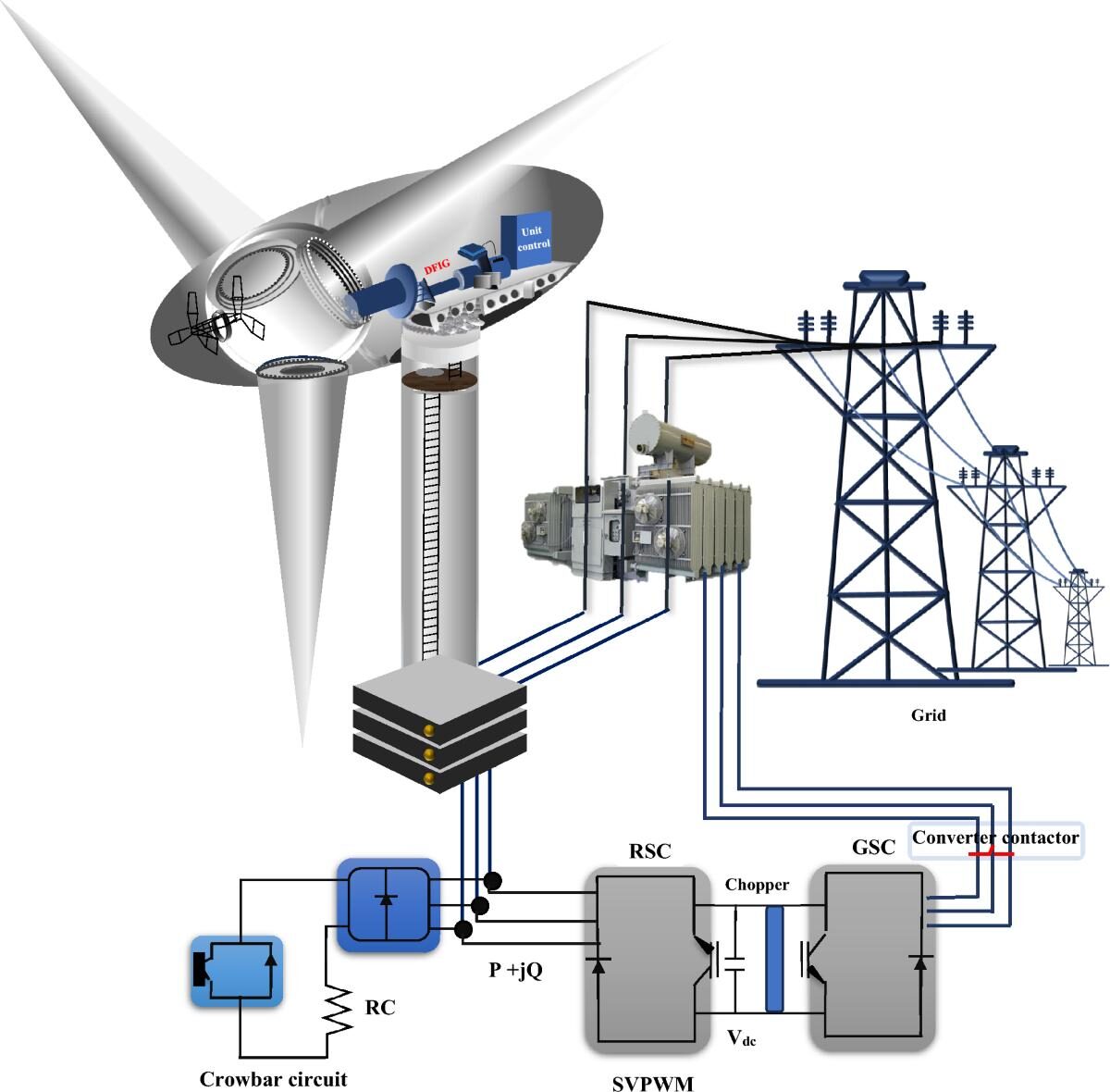
Figure 1: Integrated Dynamic Simulation Framework for Evaluating Wind Turbine Response Under Grid Fault Conditions.
Figure 1 illustrates the dynamic interaction between a utility grid and a modern wind power system during abnormal operating conditions. The framework represents typical disturbances such as voltage sags, short-circuit faults, frequency deviations, and weak-grid events that affect both DFIG and full-converter wind turbines. The diagram highlights the flow of electrical and mechanical energy through the generator, power electronic converters, DC-link, control system, and grid interface. Dynamic simulation is employed to analyze converter stress, fault ride-through capability, rotor and stator current behavior, PLL stability, electromechanical torque oscillations, and post-fault recovery performance. Such simulation-based analysis forms the foundation for controller design, protection coordination, and grid-code compliance verification in modern wind energy systems. [1]–[7]
The response of a wind turbine during a fault depends on the interaction between electrical and mechanical systems. A voltage dip may instantly change generator currents, while the mechanical rotor dynamics respond more slowly due to turbine inertia. At the same time, converters must regulate currents, maintain DC-link voltage, and prevent excessive semiconductor stress. These interactions are strongly nonlinear and require dynamic time-domain simulation for accurate prediction [2].
This research focuses on simulation techniques used to evaluate wind turbine behavior under grid faults. The analysis covers DFIG-based wind turbines and full-converter wind turbines, emphasizing fault modeling, converter response, protection mechanisms, FRT performance, and the relationship between simulation results and engineering decisions.
2. What Grid Fault Means in Simulation
A grid fault in a wind power simulation represents an abnormal operating condition where the electrical characteristics of the grid change significantly from normal operation. In engineering studies, faults are not considered rare edge conditions because power systems continuously experience disturbances caused by equipment failures, switching operations, and network changes. Since wind turbines are directly connected to the grid through converters, these events become major stress conditions for turbine control systems.
During normal operation, wind turbines operate around predefined voltage, frequency, and power references. The converter controllers regulate active and reactive power while maintaining stable current flow. However, during faults, these operating assumptions change immediately. The grid voltage may collapse, current may increase rapidly, and converter controllers may enter saturation regions.
Voltage Dips
Voltage dips are among the most common disturbances affecting wind turbines. A voltage dip occurs when the grid voltage decreases temporarily due to faults or large electrical disturbances. Voltage dips can be classified into balanced and unbalanced disturbances.
A balanced voltage dip occurs when all three phases experience approximately the same voltage reduction. This situation is commonly associated with three-phase short-circuit faults. The symmetrical voltage reduction produces high stress on converters because active power transfer capability decreases while the mechanical input power from the turbine remains almost unchanged.
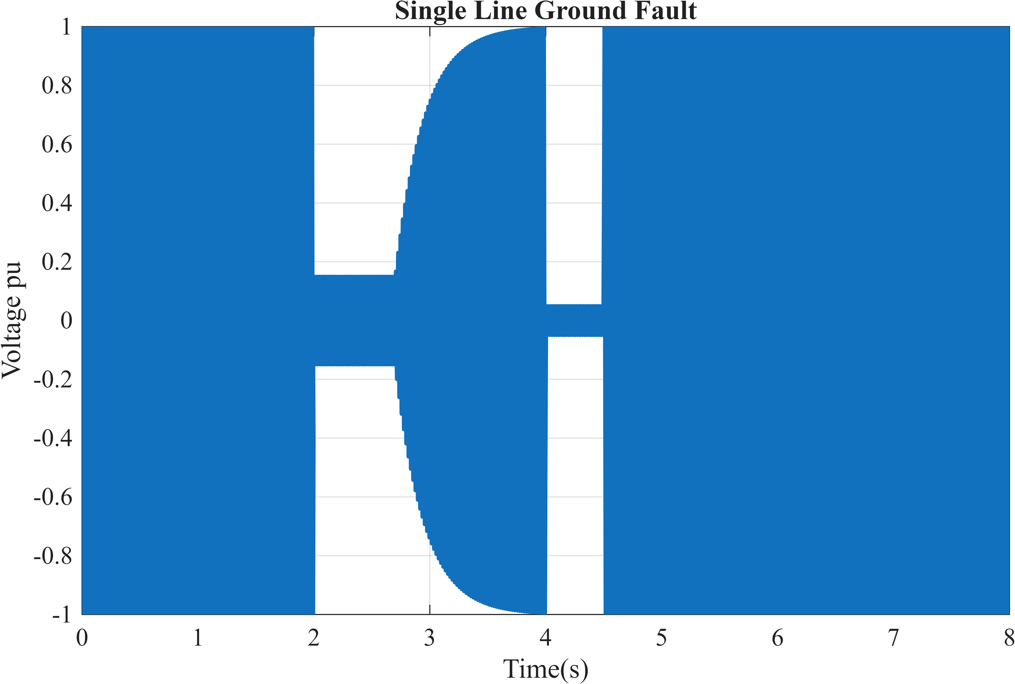
Figure 2: Single-line-to-ground fault demonstrating asymmetrical voltage disturbance and unbalanced operating conditions.
Figure 2 presents the three-phase grid voltage waveforms during a balanced three-phase fault event. A severe voltage reduction occurs between the fault initiation and clearing instants, followed by voltage recovery to nominal operating conditions. The figure demonstrates the electrical disturbance experienced by the wind turbine and provides the basis for analyzing converter response, current transients, and fault ride-through performance under symmetrical fault conditions.
Unbalanced voltage dips occur when only one or two phases are affected. These conditions are usually caused by single-line-to-ground (SLG) or phase-to-phase faults. Unbalanced faults introduce negative-sequence components that create additional oscillations in generator currents and converter control loops [3].
Short-Circuit Faults
Short-circuit faults represent direct electrical connections between phases or between a phase and ground. The major fault types considered in wind turbine studies include:
- Three-phase faults
- Two-phase faults
- Single-line-to-ground faults
Three-phase faults are generally the most severe because they create symmetrical voltage collapse. Two-phase faults introduce voltage imbalance and negative-sequence currents. Single-line-to-ground faults are the most frequently occurring faults in practical power systems and create asymmetrical electrical conditions.
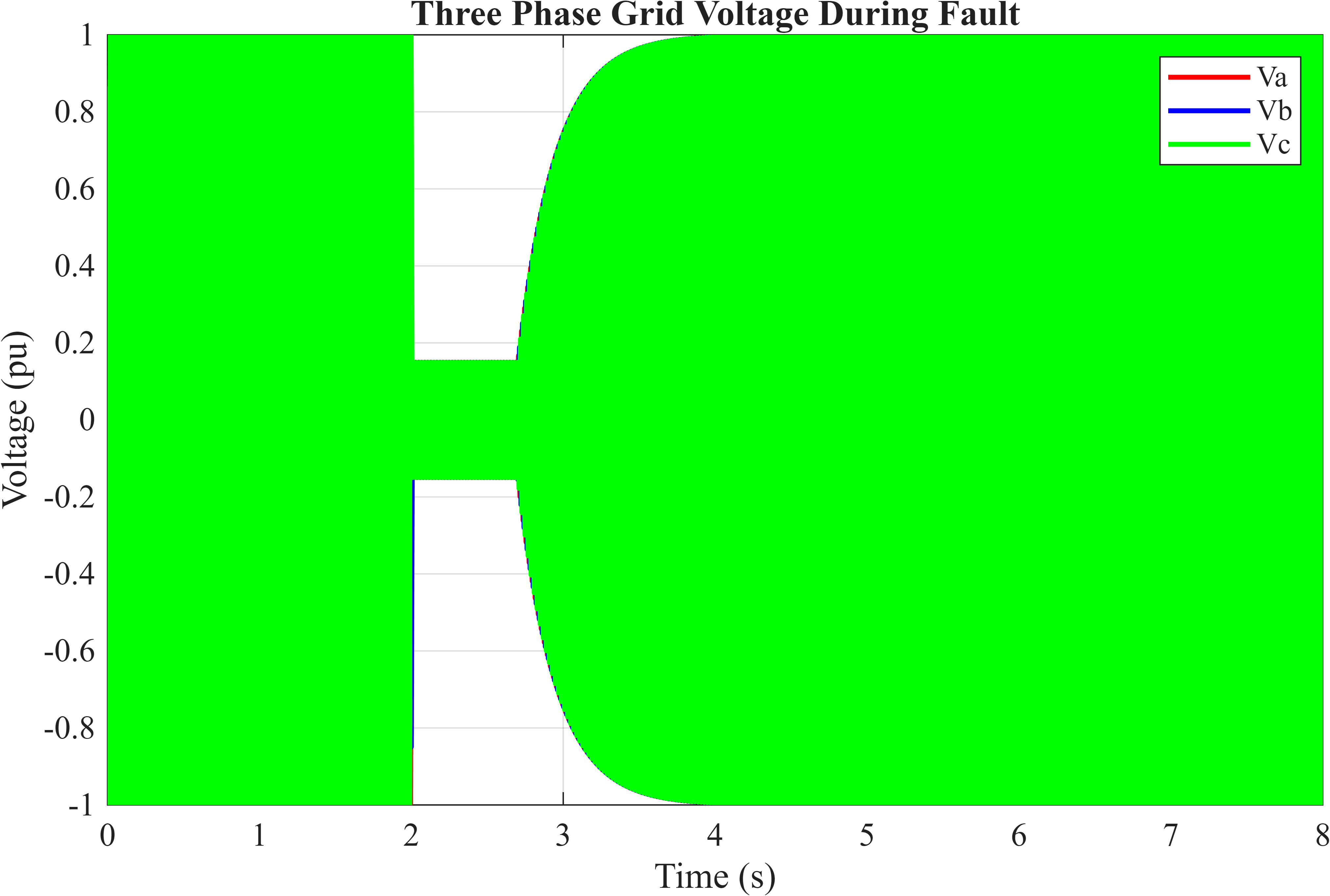
Figure 3: Three-phase voltage waveform during a balanced grid fault showing voltage collapse and recovery characteristics.
Figure 3 presents the voltage waveform during a single-line-to-ground (SLG) fault, representing one of the most common fault types in practical power systems. The fault introduces significant phase voltage imbalance and creates asymmetrical operating conditions that generate negative-sequence currents within the wind turbine generator and converter system. Such disturbances are critical for evaluating protection performance and converter stability under unbalanced grid conditions.
During short circuits, the wind turbine converter must respond quickly to prevent excessive current flow. If the current exceeds converter limits, protection mechanisms such as current limiting or crowbar circuits may activate.
Frequency Deviations
Frequency deviations occur when there is an imbalance between generation and demand. A reduction in frequency indicates insufficient generation, while an increase indicates excess generation. Wind turbines must detect these changes through control systems and may provide frequency support by modifying active power output.
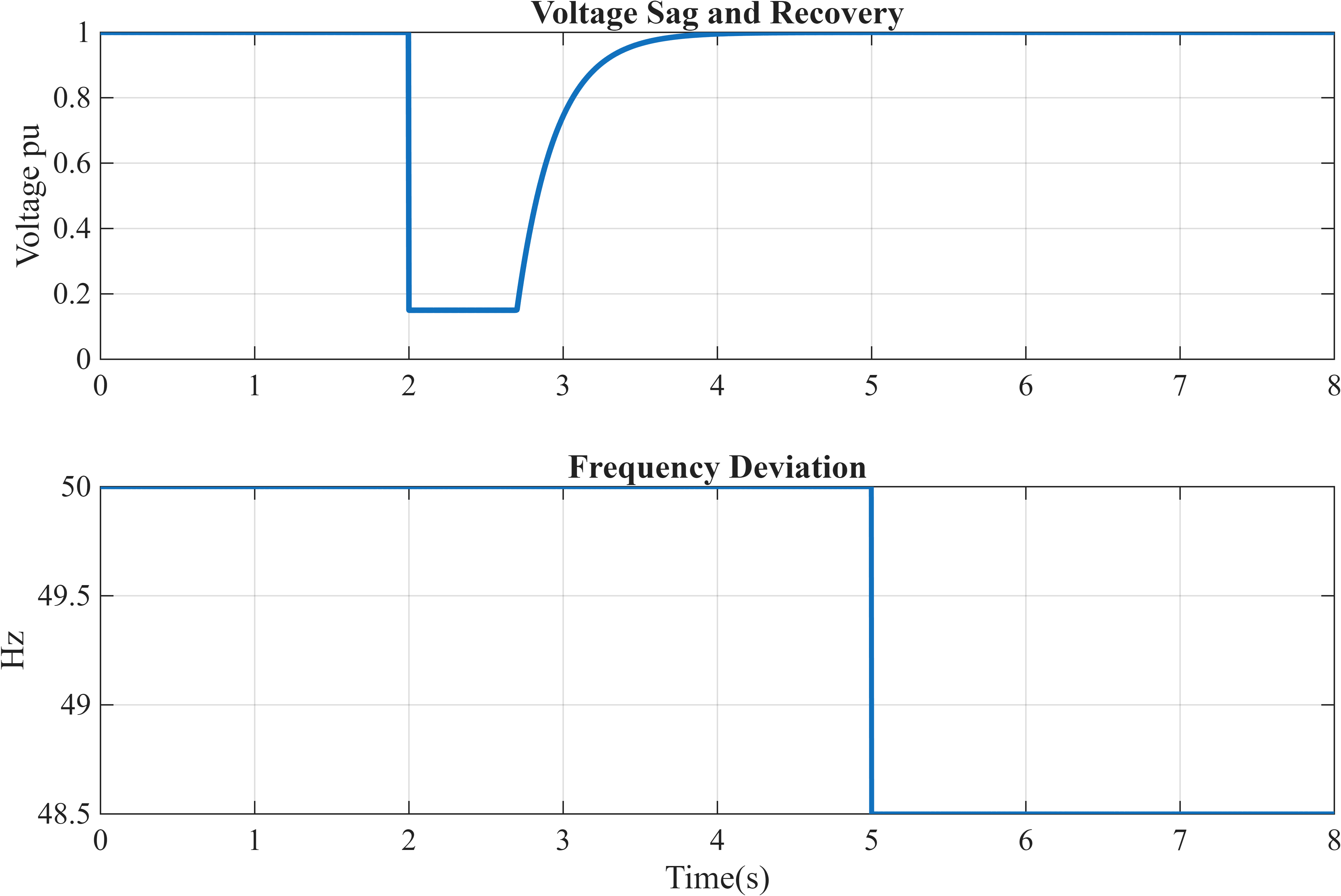
Figure 4: Voltage sag, post-fault voltage recovery, and frequency deviation used for dynamic fault simulation studies.
Figure 4 presents the dynamic grid voltage and frequency profiles used for fault simulation. The upper subplot illustrates a deep voltage sag followed by post-fault voltage recovery, while the lower subplot shows a frequency deviation event representing generation-load imbalance. These disturbances are commonly used in dynamic studies to evaluate the robustness of wind turbine control systems and grid-support capabilities.
Frequency events are slower than voltage faults but can create significant stress when combined with weak grid conditions. The phase-locked loop used for grid synchronization may experience difficulty tracking distorted voltage waveforms, resulting in inaccurate reference generation.
Grid Impedance Changes
The strength of the electrical grid significantly affects wind turbine stability. A weak grid has higher impedance and lower short-circuit capacity, causing larger voltage variations during disturbances.
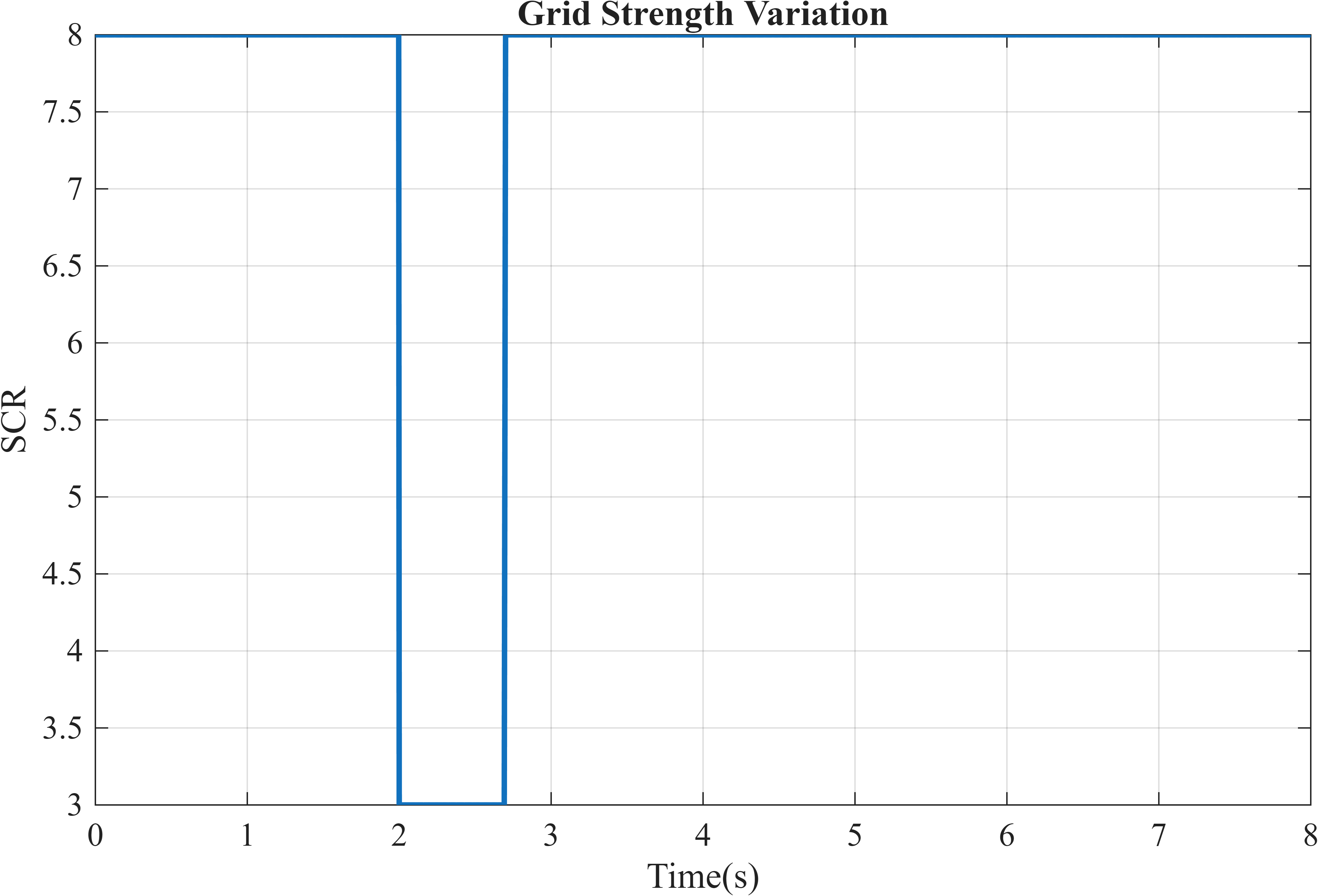
Figure 5: Variation of short-circuit ratio (SCR) representing transition from strong-grid to weak-grid conditions.
Figure 5 presents the variation of short-circuit ratio (SCR), which is commonly used to quantify grid strength. A reduction in SCR represents a weaker grid with higher effective grid impedance and reduced fault current capability. The figure highlights the operating environment under which converter-grid interactions become more pronounced and system stability becomes increasingly challenging.
Changes in grid impedance influence:
- Converter current response
- Voltage regulation
- PLL stability
- Power oscillations
A converter that operates correctly in a strong grid may become unstable in a weak grid because the interaction between converter control and grid dynamics changes significantly [4].
Sudden Load Rejection or Reconnection
Large load changes can create temporary grid disturbances. Sudden load rejection causes excess generation, resulting in frequency increase and voltage variations. Similarly, reconnection of large loads can produce temporary voltage drops and current surges.
These events demonstrate why grid faults are important design conditions rather than exceptional cases. Wind turbine controllers must maintain stability under these disturbances to ensure reliable grid operation.
Fault conditions differ fundamentally from nominal operation because electrical variables no longer follow predictable linear relationships. During faults, converter saturation, magnetic nonlinearities, and control interactions become dominant. Therefore, simplified linear assumptions quickly lose accuracy.
3. Why Steady-State Models Fail During Faults
Steady-state models are useful for evaluating normal operating points, power flow, and long-term system behavior. However, they are unsuitable for analyzing fast grid disturbances because faults involve rapid changes occurring within milliseconds. A steady-state model assumes that electrical quantities remain close to equilibrium. During faults, this assumption is immediately violated.
Quasi-Static Aerodynamic Limitations
Wind turbine aerodynamic models are often simplified using constant wind speed and average power coefficients. These assumptions may be acceptable during normal operation but fail during transient events.
Electrical faults occur much faster than aerodynamic changes. The mechanical power input cannot instantly decrease when grid voltage collapses. This mismatch causes temporary energy imbalance between the turbine rotor and electrical system. The rotor continues accelerating while electrical torque decreases, producing speed variation and torque oscillations.
Converter Model Limitations
Modern wind turbines depend heavily on power electronic converters. A simplified converter model may represent only average power transfer but ignore switching effects and current controller dynamics.
During faults, converters experience:
- Current spikes
- Semiconductor stress
- Control saturation
- Switching frequency limitations
Average converter models may hide instability modes caused by interactions between switching behavior and control loops.
Electrical and Mechanical Decoupling Problems
Electrical faults directly affect electromagnetic torque. If electrical and mechanical models are analyzed separately, important transient effects are missed.
The generator torque changes rapidly during a voltage disturbance, while the turbine shaft responds according to its inertia. This coupling creates oscillations that influence both electrical recovery and mechanical stress.
The electromechanical relationship of the wind turbine can be represented by the following dynamic equation [2]:

Where:
- J represents turbine and generator inertia,
- ωr is rotor angular speed,
- Tm is mechanical torque from the turbine,
- Te is electromagnetic generator torque,
- D represents mechanical damping.
This equation (1) shows that rotor speed changes according to the difference between mechanical input and electrical torque. During a fault, Te may decrease rapidly while Tm remains almost unchanged, creating rotor acceleration.
Incorrect Current Prediction Without Grid Impedance
Ignoring grid impedance produces inaccurate current estimation. Converter currents are directly affected by grid voltage level and network strength.
During voltage sag conditions, maintaining active power transfer requires higher current. If grid impedance is neglected, simulations may underestimate converter stress and fail to predict protection activation.
Typical failures predicted by dynamic simulation include:
Overcurrent During Voltage Sag
When voltage decreases, the converter attempts to maintain power transfer by increasing current. Without proper limitation, rotor and stator currents may exceed safe operating limits.
DC-Link Overvoltage
In converter-based wind turbines, reduced power export during faults causes energy accumulation in the DC-link capacitor. This creates voltage rise that may damage converter components.
Loss of Synchronism
The PLL is responsible for tracking grid phase angle. Distorted voltages during faults can create synchronization errors, causing unstable converter operation.
DFIG Rotor-Side Converter Instability
In DFIG systems, the rotor-side converter directly controls rotor currents. Since rotor currents become highly disturbed during faults, the rotor-side converter is often the most vulnerable component.
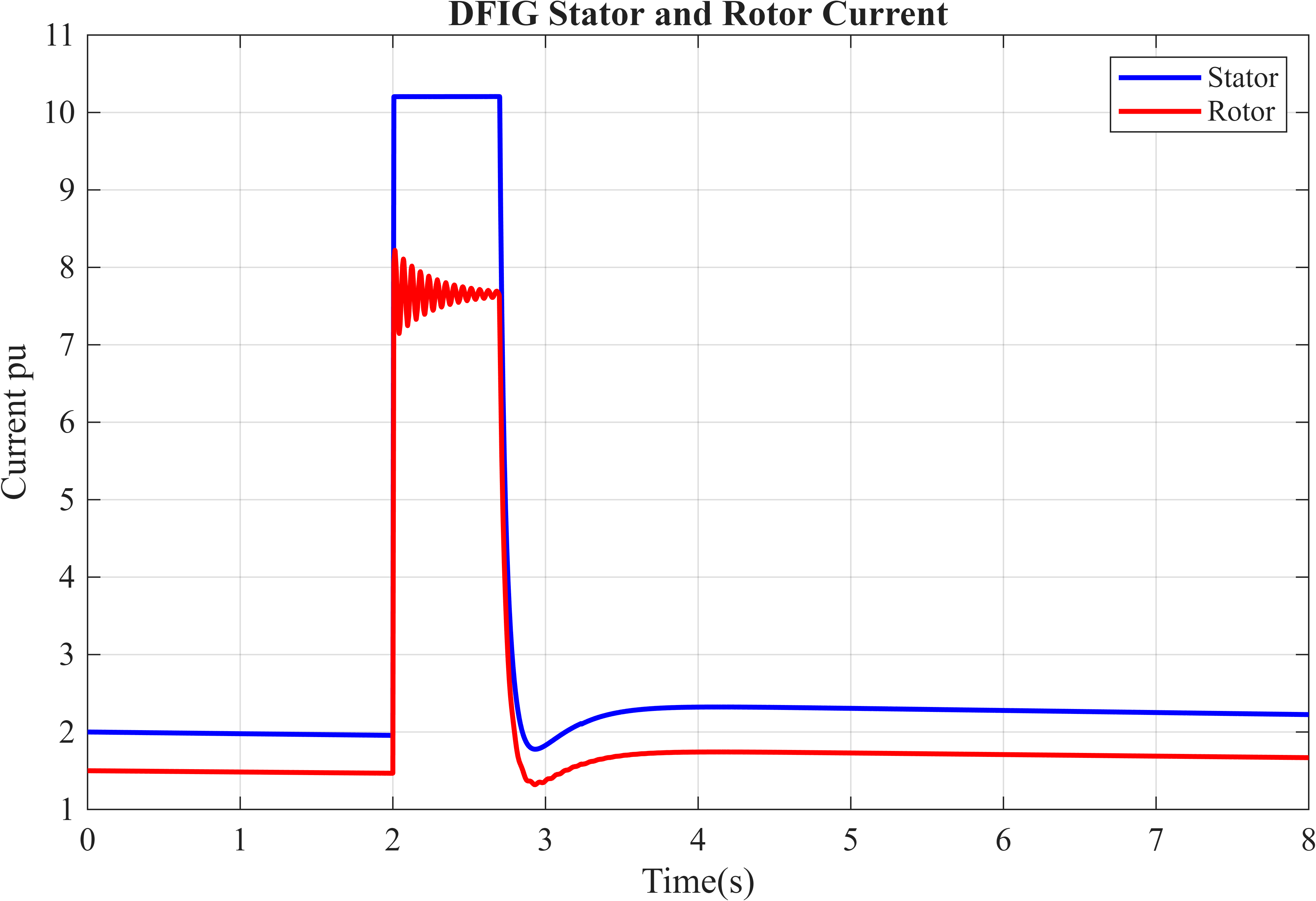
Figure 6: Transient stator and rotor current response during voltage sag conditions showing converter stress and overcurrent behavior.
Figure 6 presents the transient stator and rotor current responses of the DFIG wind turbine during a voltage fault. The sudden increase in current magnitude immediately after fault occurrence demonstrates the electrical stress imposed on the machine and power electronic converters. The results emphasize the importance of dynamic simulation for predicting overcurrent conditions and evaluating converter protection strategies.
4. Fault Modeling in Dynamic Simulation Environments
Dynamic simulation environments allow engineers to reproduce realistic grid disturbances and observe system behavior over time. Unlike steady-state analysis, time-domain simulation captures the complete sequence of events before, during, and after a fault.
In practical engineering workflows, grid faults are introduced using programmable voltage sources, switching events, and impedance-based fault models.
Programmable Grid Voltage Sources
A programmable source allows the simulation of voltage variations such as:
- Voltage sag
- Voltage recovery
- Phase imbalance
- Frequency deviation
The voltage profile can be defined according to actual grid disturbance measurements or grid-code requirements.
Fault Blocks and Switching Events
Fault blocks simulate electrical short circuits by changing network connections at specified times. Engineers define:
- Fault initiation time
- Fault clearing time
- Fault impedance
- Fault type
This allows comparison between different fault scenarios.
Impedance-Based Fault Injection
Fault severity depends strongly on fault impedance. A low impedance fault produces deeper voltage collapse and higher current stress, while a high impedance fault creates smaller disturbances.
Correct impedance selection is critical because unrealistic values may produce inaccurate conclusions.
Time-Domain Simulation Requirement
Phasor-based analysis assumes sinusoidal steady-state behavior and is useful for power flow studies. However, it cannot capture fast transient effects such as:
- Converter current spikes
- PLL instability
- Switching stress
- Protection activation
- DC-link dynamics
Time-domain simulation calculates system variables continuously during the disturbance and provides a realistic representation of fault evolution [5].
MATLAB, Simulink, and power-system simulation environments are commonly used because they allow integration of electrical networks, generators, converters, and control algorithms in a unified model.
5. Converter and Control Response During Faults
Modern wind turbines rely heavily on power electronic converters to control energy transfer between the generator and the electrical grid. The converter system acts as the interface between the variable-speed turbine generator and the fixed-frequency power network. During normal operation, converters regulate active power, reactive power, generator torque, and grid synchronization. However, during grid faults, the converter becomes the main component responsible for maintaining stability and preventing equipment damage.
When a grid fault occurs, the voltage reduction causes immediate changes in electrical currents. Since the turbine continues receiving mechanical energy from the wind, the mismatch between mechanical input and electrical output creates temporary energy accumulation. The converter must handle this imbalance while maintaining safe current and voltage levels.
Current Surge in Rotor and Stator Circuits
During a voltage dip, the electromagnetic conditions of the generator change rapidly. In DFIG-based wind turbines, the stator is directly connected to the grid, while the rotor is connected through a rotor-side converter. When the stator voltage decreases, the magnetic flux changes and induces transient currents in both stator and rotor circuits.
The major effects include:
- Increased stator current
- Rotor current oscillation
- Converter current saturation
- Electromagnetic torque variation
The converter controller attempts to maintain the desired current references, but during severe faults the required current may exceed converter capability.
Current Controller Saturation
Wind turbine converters use current control loops to regulate d-axis and q-axis currents. Under normal operation, these controllers maintain accurate tracking of current references. During faults, however, the required compensation current may exceed the converter rating.
When this happens:
- Controller outputs reach their maximum limits
- Reference tracking becomes inaccurate
- Harmonic distortion increases
- Recovery becomes slower
Current saturation is one of the main causes of instability during fault recovery because the converter temporarily loses full control authority.
DC-Link Voltage Spike
Full-converter wind turbines and DFIG systems with back-to-back converters use a DC-link capacitor to exchange energy between converter stages. During a fault, the grid-side converter may not be able to deliver all available generator power to the grid. The excess energy is stored in the DC-link capacitor, causing voltage increase.
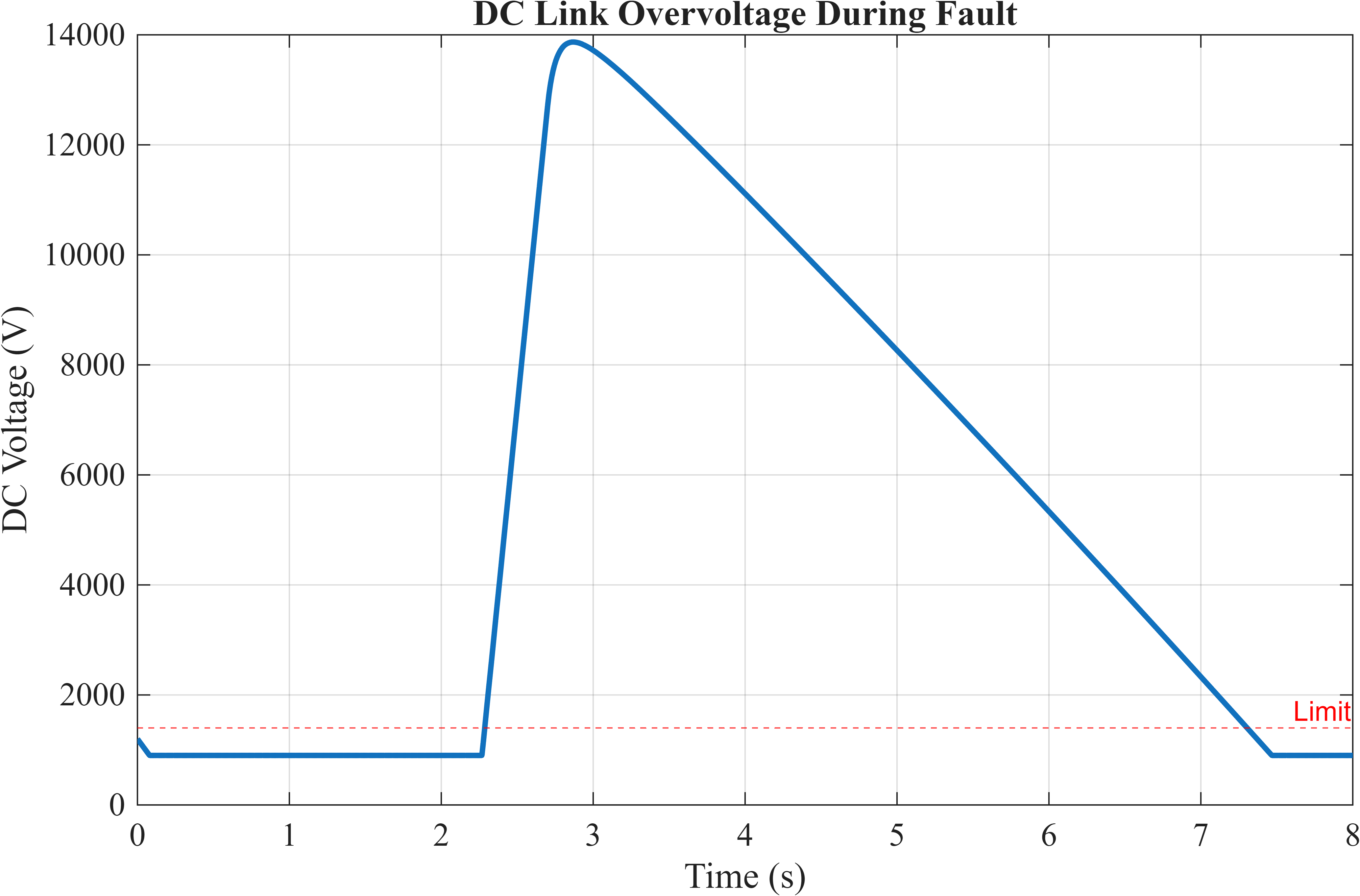
Figure 7: DC-link voltage dynamics during fault conditions illustrating energy accumulation and overvoltage stress.
You can download the Project files here: Download files now. (You must be logged in).
Figure 7 presents the rotor speed variation and electromagnetic torque oscillations during grid fault conditions. The temporary reduction in electrical torque creates an imbalance between mechanical input power and electrical output power, leading to transient rotor acceleration and torque fluctuations. These results illustrate the electromechanical coupling that exists between the generator and drivetrain during fault events.
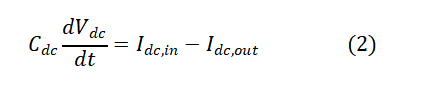
The DC-link voltage dynamic relationship can be represented by the energy balance equation [6]:
Where:
- Cdc represents the DC-link capacitance,
- Vdc is the DC-link voltage,
- Idc,in represents incoming converter current,
- Idc,out represents outgoing grid-side converter current.
This equation (2) explains that DC-link voltage increases when the incoming energy exceeds the energy delivered to the grid.
Excessive DC-link voltage can cause:
- Converter semiconductor stress
- Protection activation
- Converter shutdown
- Reduced fault ride-through capability
PLL Instability Under Distorted Grid Voltage
The phase-locked loop is responsible for synchronizing the converter with grid voltage. It estimates grid angle and frequency, allowing the converter controller to generate appropriate reference signals.
During faults, voltage distortion and imbalance can cause:
- Incorrect phase estimation
- Frequency oscillation
- Current reference errors
- Converter instability
Weak grids are especially challenging because small disturbances create large voltage variations. PLL tuning therefore becomes a critical factor in wind turbine stability.
Switching Stress in Grid-Side Converters
The grid-side converter controls power injection into the network. During fault conditions, it experiences increased stress due to:
- Higher current demand
- Increased switching losses
- Thermal loading
- Control effort increase
Switching stress is especially important for semiconductor reliability because repeated fault events can accelerate device degradation.
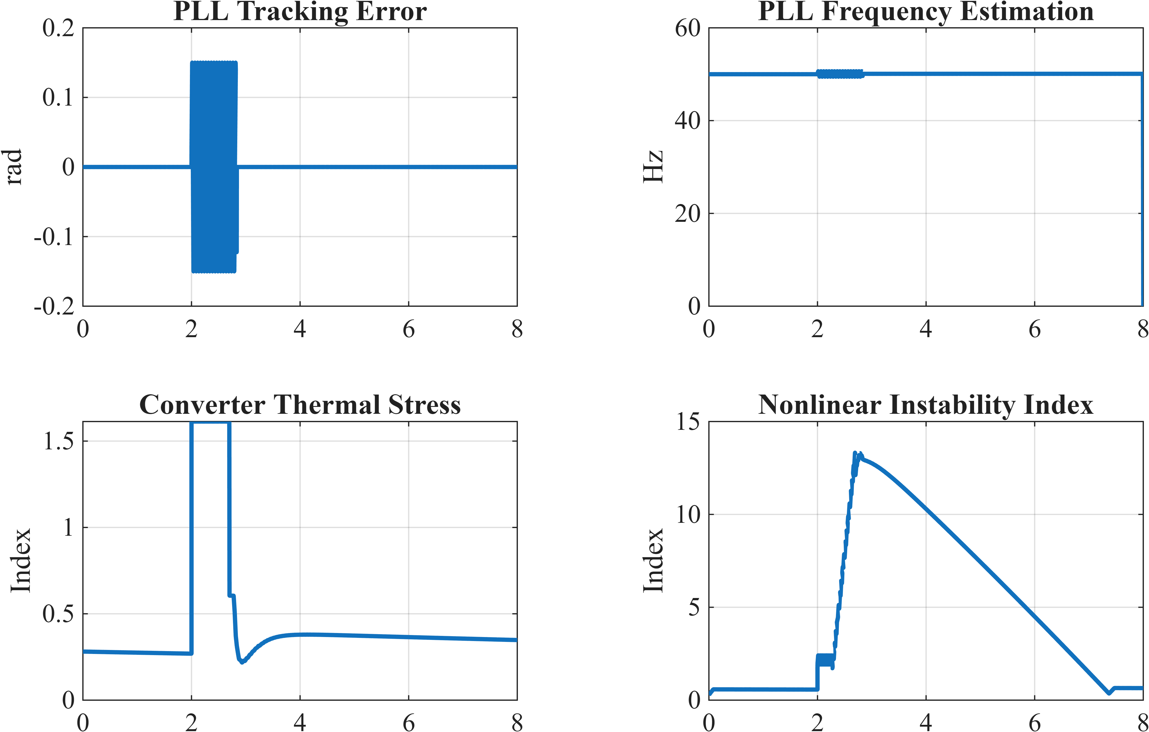
Figure 8: PLL tracking error, frequency estimation, converter thermal stress, and instability indicators during grid disturbances.
Figure 8 presents the active and reactive power behavior of the wind turbine throughout the fault and recovery periods. Active power decreases significantly during the voltage dip, while reactive power support increases to assist grid voltage recovery. The figure demonstrates the capability of the control system to satisfy fault ride-through requirements and provide grid-support functionality during disturbances.
DFIG-Specific Fault Behavior
Doubly fed induction generators are widely used in wind turbines because they provide variable-speed operation with reduced converter size. However, the partial converter structure makes them sensitive during severe grid disturbances.
In a DFIG system:
- The stator is directly connected to the grid
- The rotor is connected through the rotor-side converter
- The rotor-side converter controls torque and reactive power
During a voltage fault, the rotor-side converter experiences the highest stress because it must control rapidly changing rotor currents.
Rotor-Side Converter Vulnerability
The rotor-side converter must maintain control over:
- Rotor flux
- Electromagnetic torque
- Reactive power
During severe voltage dips, rotor currents may exceed converter limits. If current protection is not activated, converter switches may experience destructive stress.
Crowbar Protection Activation
The crowbar is a protection mechanism used in DFIG turbines to protect the rotor-side converter.
The operating principle is:
1. Detect excessive rotor current
2. Disconnect normal rotor control
3. Insert protective resistance
4. Limit rotor current
5. Allow turbine recovery after fault clearance
The crowbar changes turbine operation from controlled mode to protected mode.
Although effective for protection, crowbar activation temporarily reduces controllability because rotor current regulation is interrupted.
Transition Between Controlled and Uncontrolled Operation
Before the crowbar activates, the converter attempts to regulate rotor currents normally. After activation, the rotor circuit becomes partially uncontrolled.
This transition produces:
- Torque variation
- Reactive power disturbance
- Recovery delay
Therefore, crowbar threshold selection is an important design decision. A very low threshold may cause unnecessary activation, while a very high threshold may fail to protect the converter.
Full-Converter Wind Turbine Fault Response
Full-converter wind turbines use a complete power electronic interface between the generator and the grid. Unlike DFIG turbines, the generator is isolated from grid disturbances by the converter.
The main fault response occurs through:
- Generator-side converter
- DC-link capacitor
- Grid-side converter
- Grid-Side Converter Dominance
The grid-side converter directly manages power exchange with the network. During faults, it becomes responsible for:
- Reactive current injection
- Voltage support
- DC-link regulation
- Grid synchronization
Because the converter carries the full turbine power, it experiences greater electrical stress compared with DFIG partial converters.
DC-Link Energy Buffering
The DC-link acts as an energy storage element. During faults:
- Generator power continues arriving
- Grid power transfer decreases
- DC-link voltage rises
The converter controller must reduce incoming energy or increase reactive support to maintain stability.
6. Fault Ride-Through (FRT) Simulation
Fault ride-through capability defines the ability of a wind turbine to remain connected to the grid during temporary disturbances. Modern grid codes require renewable generators to support the network rather than disconnect during faults [7].
The main objective of FRT simulation is to verify that wind turbines can survive disturbances while maintaining stable operation.
Low Voltage Ride Through (LVRT)
LVRT requirements define the minimum voltage profile that a wind turbine must tolerate without disconnecting.
During LVRT operation, the turbine must:
- Stay connected during voltage sag
- Maintain converter operation
- Provide reactive support
- Recover power after fault clearance
The voltage-time curve defined by grid codes determines acceptable operation regions.
Reactive Current Injection During Faults
Modern grid codes require wind turbines to provide reactive current during voltage dips.
Reactive current injection helps:
- Restore voltage magnitude
- Support grid stability
- Reduce recovery time
The converter increases reactive current reference when measured voltage decreases.
This creates a temporary priority shift:
Normal operation:
- Active power control priority
Fault operation:
- Voltage support priority
Recovery Phase Dynamics
Fault clearance does not immediately restore normal operation. After fault removal, the system experiences a recovery period.
During recovery:
- DC-link voltage decreases
- PLL resynchronizes
- Currents return to normal
- Power output increases gradually
Fast recovery may cause additional stress, so controllers must balance speed and stability.
Grid Code Compliance Verification
FRT simulation verifies:
- Voltage recovery capability
- Reactive power support
- Current limitation
- Converter stability
- Post-fault power restoration
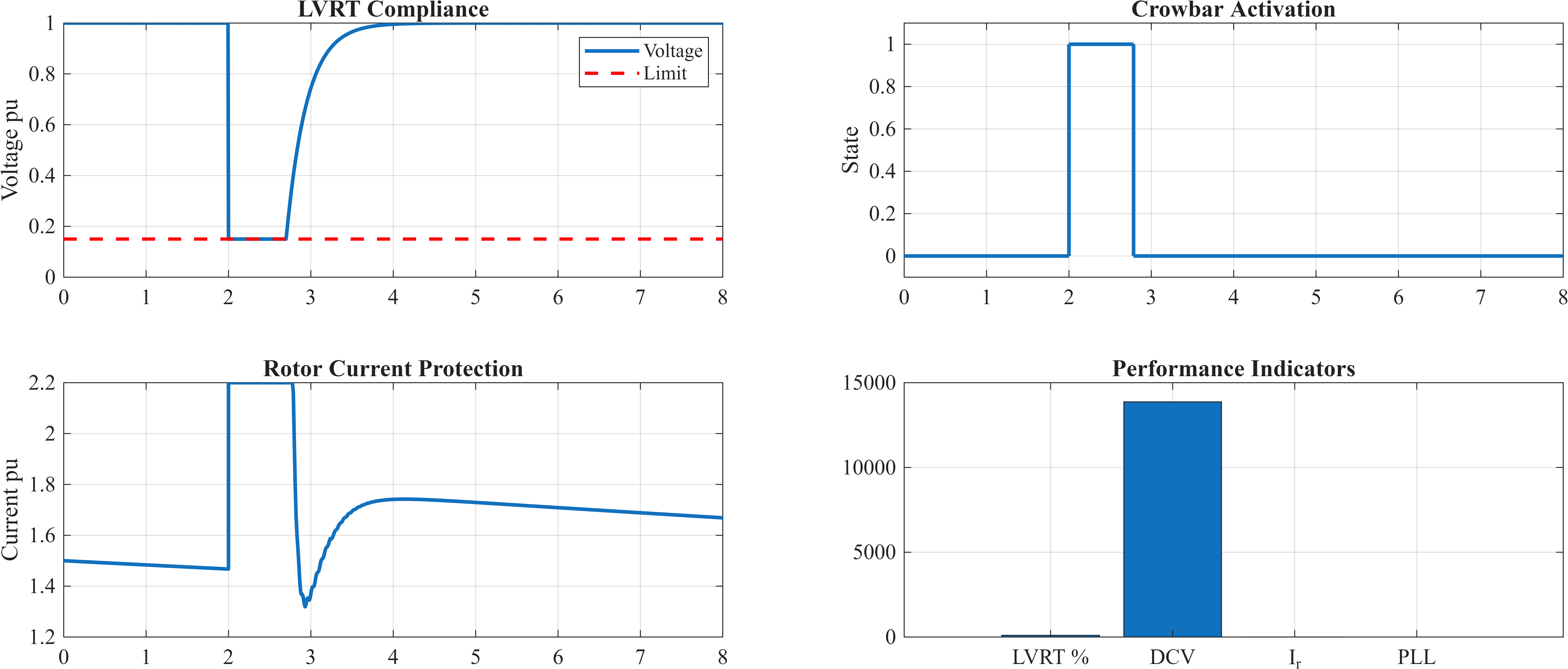
Figure 9: Low-voltage ride-through verification, crowbar activation, rotor current limitation, and fault-performance indicators.
You can download the Project files here: Download files now. (You must be logged in).
Figure 9 presents the DC-link voltage response during the fault event. Due to the temporary reduction in power transfer capability between the converter and the grid, energy accumulates within the DC-link capacitor, resulting in a voltage rise. Monitoring DC-link behavior is essential for evaluating converter protection requirements and preventing overvoltage-related failures.
Simulation is performed before field testing because it reduces development cost and identifies weak control areas.
7. Electromechanical Stress During Grid Disturbances
Wind turbines are coupled electromechanical systems where electrical disturbances influence mechanical components.
A grid fault may appear as an electrical event, but its consequences can propagate into the mechanical drivetrain.
Torque Oscillations
During faults, electromagnetic torque changes rapidly because generator electrical conditions change.
The mechanical turbine torque cannot change instantly because aerodynamic dynamics are slower. This mismatch creates torque oscillations.
These oscillations affect:
- Gearbox
- Main shaft
- Generator coupling
Drivetrain Stress During Current Changes
Large current variations create rapid electromagnetic torque changes.
Repeated faults may cause:
- Shaft vibration
- Mechanical fatigue
- Increased bearing stress
Although mechanical damage is usually not immediate, repeated electrical disturbances can reduce component lifetime.
Aerodynamic Inertia Delay Versus Electrical Transients
Electrical systems respond within milliseconds, while mechanical systems respond over seconds.
This difference creates temporary energy imbalance.
For example:
- Electrical output drops immediately
- Mechanical input remains almost constant
- Rotor accelerates
Dynamic simulation is required because steady-state models cannot represent this time-scale difference.
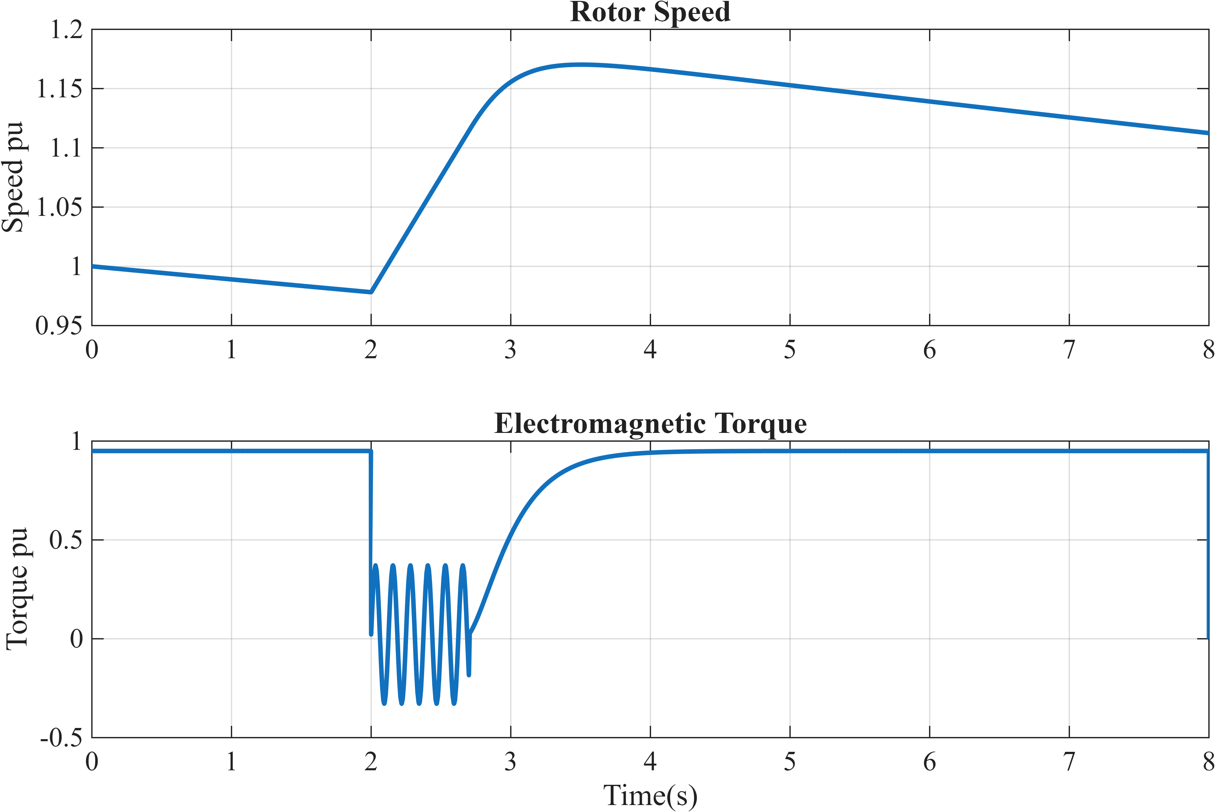
Figure 10: Rotor speed variation and electromagnetic torque oscillations caused by electrical disturbances.
Figure 10 presents the dynamic behavior of the phase-locked loop (PLL), converter thermal stress, and overall instability indicators during grid disturbances. The PLL tracking error and frequency estimation results illustrate synchronization challenges under distorted voltage conditions, while the thermal and instability indices provide quantitative measures of converter stress. These results are valuable for controller tuning and stability assessment under weak-grid and fault scenarios.
Shaft Fatigue Accumulation
Repeated grid faults create cyclic mechanical loading.
Even if each event does not cause immediate failure, accumulated stress may reduce turbine lifetime.
Therefore, fault simulations are also useful for mechanical reliability studies.
8. Nonlinear Dynamics and Instability Mechanisms
Wind power systems contain multiple nonlinear components, including converters, magnetic circuits, controllers, and protection systems.
These nonlinear effects are often invisible in simplified models.
Magnetic Saturation
Generator magnetic circuits become nonlinear during high fault currents.
Saturation changes:
- Flux relationship
- Inductance values
- Current response
Linear models assume constant parameters and therefore underestimate fault effects.
Control Loop Interaction With Grid Impedance
Converter controllers and grid impedance interact dynamically.
A controller designed for a strong grid may become unstable in a weak grid because:
- Voltage feedback changes
- PLL response changes
- Current control bandwidth becomes unsuitable
Bifurcation-Like Converter Instability
Converter systems may experience sudden transitions from stable to unstable behavior due to parameter changes.
Small variations in:
- Grid strength
- Controller gain
- Delay
can create large changes in system response.
Sampling Time and Switching Frequency Sensitivity
Digital controllers operate with finite sampling time.
Incorrect selection of:
- Sampling frequency
- PWM frequency
- Controller bandwidth
may create oscillations or instability.
Linearized models often ignore these effects, making full nonlinear simulation necessary for accurate analysis.
Simulation Setup and Common Modeling Errors
Accurate fault simulation depends not only on the mathematical model but also on correct implementation of electrical, mechanical, and control domains. A wind turbine simulation combines aerodynamic models, generator equations, converter switching models, protection systems, and grid representations. Any inconsistency between these components can lead to incorrect conclusions.
A properly designed simulation environment should maintain consistency between:
- Electrical time constants
- Mechanical response
- Converter switching behavior
- Controller sampling rates
- Grid representation
MATLAB, Simulink, and power-system simulation toolboxes are commonly used for this purpose because they provide integrated modeling capabilities for generators, converters, control systems, and grid networks.
Unrealistic Fault Impedance Values
Fault impedance determines the severity of a grid disturbance. A very low impedance fault may create an unrealistic voltage collapse and excessive current, while a very high impedance fault may underestimate converter stress.
Incorrect impedance selection can lead to:
- Wrong current predictions
- Incorrect protection activation
- False stability conclusions
Therefore, fault impedance values should be selected according to realistic network conditions and utility data whenever available.
Ignoring Converter Switching Behavior
A common modeling mistake is using only average converter models without considering switching effects.
Average models are useful for long-duration studies but may fail during:
- Fast transient events
- Current spikes
- Semiconductor stress analysis
Switching behavior affects:
- Harmonic generation
- Thermal losses
- Controller interaction
For detailed fault analysis, switching-level converter models may be required.
Incorrect PLL Parameterization
The PLL is one of the most sensitive components in converter-based wind turbines.
Incorrect PLL tuning can create:
- Poor synchronization
- Excessive phase error
- Oscillatory current response
A PLL that is too slow cannot track rapid disturbances, while a PLL that is too fast may amplify grid disturbances.
Therefore, PLL bandwidth must be selected according to grid strength and converter control requirements.
Oversimplified Turbine Inertia Modeling
Mechanical inertia strongly affects transient behavior.
Using an incorrect inertia value changes:
- Rotor acceleration
- Torque oscillation
- Recovery response
A simplified mechanical model may underestimate drivetrain stress during faults.
Mismatched Electrical and Mechanical Time Steps
Electrical systems operate much faster than mechanical systems.
Electrical transients may occur within milliseconds, while mechanical dynamics evolve over seconds.
Using identical simulation time steps for both domains may produce:
- Numerical errors
- Slow simulation
- Incorrect transient prediction
Multi-rate simulation techniques are often required for accurate analysis.
Importance of Model Consistency
All simulation components must represent compatible physical behavior. A highly detailed converter model combined with an oversimplified mechanical model may produce misleading results.
The goal is not maximum complexity but an appropriate level of detail that captures the important fault dynamics.
Design Decisions Based on Fault Simulation
Fault simulation is not only an analysis technique; it is a decision-making tool used during wind turbine design and grid integration.
The results obtained from dynamic simulation directly influence control strategies, protection settings, and hardware selection.
Tuning Converter Current Limits
Converter current limits must be selected carefully.
If limits are too low:
- Reactive support capability decreases
- LVRT performance reduces
- Voltage recovery becomes slower
If limits are too high:
- Semiconductor stress increases
- Thermal damage risk increases
Fault simulations help identify the optimal current limit while maintaining converter safety.
Selecting Crowbar Protection Thresholds
Crowbar activation thresholds must balance protection and controllability.
A properly selected threshold ensures:
- Rotor converter protection
- Reduced unnecessary activation
- Faster recovery
Simulation allows engineers to test different thresholds before hardware implementation.
Optimizing Control Gains
Converter controllers require tuning for stable operation under both normal and disturbed conditions.
Fault simulations are used to optimize:
- Current controller gains
- PLL parameters
- Reactive power control
- Voltage regulation loops
The objective is to maintain stability during severe disturbances without reducing normal performance.
Improving Grid-Code Compliance Margins
Grid codes define minimum performance requirements during faults.
Simulation helps engineers create additional safety margins by evaluating:
- Worst-case faults
- Weak grid operation
- Multiple disturbance scenarios
A turbine that only satisfies the minimum requirement may fail under unexpected field conditions.
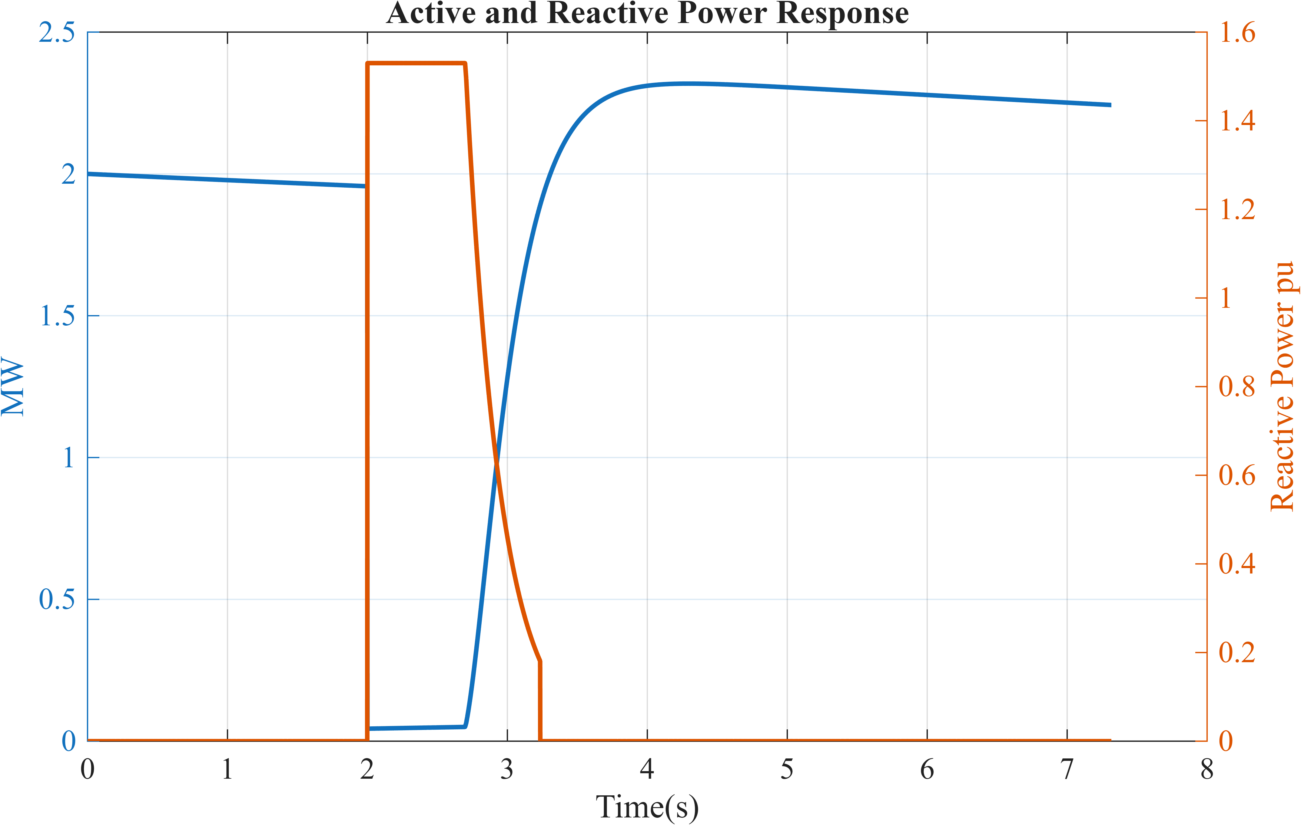
Figure 11: Active and reactive power dynamics used for controller tuning, reactive support verification, and grid-code compliance assessment.
You can download the Project files here: Download files now. (You must be logged in).
Figure 11 presents the low-voltage ride-through (LVRT) verification results together with crowbar protection activation, rotor current limiting, and key performance indicators. The figure demonstrates the ability of the wind turbine to remain connected during severe voltage disturbances while maintaining converter protection and current regulation. These results are directly related to grid-code compliance verification and fault ride-through capability assessment.
Redesigning Control Architecture
If simulations reveal instability, the control structure can be improved.
Possible modifications include:
- Improved PLL algorithms
- Adaptive current control
- Additional damping controllers
- Enhanced protection logic
Dynamic simulation therefore supports continuous improvement of turbine technology.
Iterative Simulation Workflow
Wind turbine fault analysis follows an iterative engineering process rather than a single simulation run.
The typical workflow is:
Simulation → Fault Injection → Instability Detection → Controller Redesign → Re-Simulation
This process allows engineers to gradually improve system performance.
Initial Simulation
The first stage evaluates the turbine under normal and fault conditions.
Engineers observe:
- Voltage response
- Current behavior
- Power recovery
- Converter stress
Fault Injection
Multiple fault scenarios are tested, including:
- Three-phase faults
- Two-phase faults
- Single-line-ground faults
- Voltage dips
- Frequency disturbances
- Weak grid conditions
Testing multiple scenarios is important because the worst-case condition may not always be the most obvious fault.
Instability Detection
Simulation results are analyzed for:
- Current overshoot
- DC-link voltage rise
- PLL error
- Torque oscillation
- Converter saturation
These indicators identify possible weaknesses.
Controller Redesign
Based on detected problems, engineers modify:
- Control gains
- Current limits
- Protection thresholds
- Converter parameters
The system is then simulated again.
Identifying Worst-Case Conditions
Worst-case scenarios are determined by comparing:
- Maximum current stress
- Maximum voltage deviation
- Maximum instability index
- Slowest recovery time
This allows targeted improvement instead of unnecessary redesign.
When Model Refinement Stops Adding Value
A model should not become unnecessarily complex.
Additional detail is useful only when it changes engineering decisions.
For example:
- Adding switching detail is valuable for semiconductor stress analysis
- Adding unnecessary aerodynamic complexity may not improve fault prediction
The final model should provide accurate results with reasonable computational cost.
Correlation with Field Events
Although simulation provides valuable predictions, real grid events may differ due to practical conditions that are difficult to model perfectly.
Field measurements are essential for validating and improving simulation models.
Unmodeled Grid Impedance Variation
Actual grids experience continuous changes due to:
- Network switching
- Generator dispatch changes
- Transmission configuration
These variations influence converter response.
A model based on fixed impedance may not represent every operating condition.
Measurement Noise and Delays
Real systems contain:
- Sensor noise
- Communication delays
- Filtering effects
These factors influence controller response and may create differences between simulation and field behavior.
Protection System Interactions
Real wind farms include multiple protection layers:
- Relays
- Circuit breakers
- Converter protection
- Grid protection systems
Interaction between these systems can modify fault response.
Converter Parameter Drift
Converter parameters may change over time due to:
- Temperature effects
- Component aging
- Manufacturing variation
These changes can influence control performance.
Updating Models Using Operational Data
Modern wind farms collect operational measurements that can be used to improve simulation accuracy.
Measured data can update:
- Grid impedance estimation
- Controller parameters
- Converter models
- Protection settings
This creates a continuous improvement cycle between simulation and field operation.
Role of Fault Simulation in Grid Compliance
Grid codes require renewable energy systems to support network stability during disturbances. Compliance testing ensures that wind turbines do not disconnect unnecessarily and contribute positively during grid events.
Fault simulation is a fundamental requirement before physical testing.
LVRT Capability Verification
Grid operators require wind turbines to remain connected during specified voltage dips.
Simulation verifies:
- Voltage tolerance
- Current limitation
- Recovery performance
Reactive Power Support During Faults
Wind turbines must provide reactive current support during disturbances.
Simulation confirms that:
- Converter capacity is sufficient
- Voltage support requirements are achieved
- Recovery is stable
Post-Fault Recovery Requirements
After fault clearance, turbines must restore power smoothly.
Fast recovery without proper control may cause:
- Oscillations
- Converter stress
- Grid instability
Simulation helps determine suitable recovery rates.
Certification Testing Alignment
Before certification tests, manufacturers perform extensive simulation studies.
These studies reduce:
- Testing time
- Hardware risk
- Development cost
Simulation results are used as evidence that the turbine design meets grid requirements.
Therefore, fault simulation is not only documentation; it is a necessary engineering step for successful grid integration.
Conclusion
Grid faults represent some of the most challenging operating conditions for modern wind power systems. The increasing penetration of converter-based renewable generation requires accurate understanding of turbine behavior during voltage disturbances, frequency variations, and weak grid conditions.
This paper demonstrated that steady-state models cannot accurately represent fault behavior because they ignore fast electrical transients, converter limitations, control interactions, and electromechanical coupling. Dynamic time-domain simulation provides a realistic approach for evaluating these effects.
Fault simulations reveal important phenomena including rotor and stator current surges, DC-link voltage rise, PLL instability, converter saturation, torque oscillations, and protection activation. For DFIG wind turbines, rotor-side converter protection and crowbar operation are critical during faults. For full-converter turbines, grid-side converter control and DC-link management dominate the fault response.
Fault ride-through simulation enables verification of LVRT performance, reactive current injection capability, and post-fault recovery. The results support engineering decisions related to controller tuning, converter sizing, protection design, and grid-code compliance.
A complete engineering workflow connects simulation results with practical design improvements through repeated testing, fault injection, instability detection, and controller refinement. Correlation with field measurements further improves model accuracy and ensures reliable real-world operation.
Therefore, dynamic grid fault simulation should be considered an essential design and validation tool for wind energy systems rather than only a theoretical analysis method.
References
[1] T. Ackermann, Wind Power in Power Systems, 2nd ed., Wiley, 2012.
[2] P. Kundur, Power System Stability and Control, McGraw-Hill, 1994.
[3] J. Morren and S. W. H. de Haan, “Ridethrough of wind turbines with doubly-fed induction generator during a voltage dip,” IEEE Transactions on Energy Conversion, vol. 20, no. 2, pp. 435–441, 2005.
[4] L. Fan and Z. Miao, “Wind turbine integration into weak grids with PLL dynamics,” IEEE Transactions on Power Systems, vol. 32, no. 4, pp. 3018–3027, 2017.
[5] P. Krause, O. Wasynczuk, S. Sudhoff, and S. Pekarek, Analysis of Electric Machinery and Drive Systems, 3rd ed., Wiley, 2013.
[6] N. Mohan, T. Undeland, and W. Robbins, Power Electronics: Converters, Applications, and Design, Wiley, 2003.
[7] International Electrotechnical Commission, “Wind turbines – Part 21: Measurement and assessment of power quality characteristics,” IEC 61400-21.
You can download the Project files here: Download files now. (You must be logged in).











Responses