

Simulation and Performance Analysis of a Grid-Connected Wind Power System Using a Permanent Magnet Synchronous Generator in PLECS


Author: Waqas Javaid
Abstract
The increasing demand for clean and sustainable electrical energy has accelerated the development of advanced wind energy conversion systems capable of delivering high efficiency and improved grid compatibility. Among various renewable generation technologies, permanent magnet synchronous generator (PMSG)-based wind turbines have become a preferred solution because of their high power density, gearbox-free operation, superior efficiency, and excellent dynamic response under varying wind conditions. Modern grid-connected wind power systems also require sophisticated power electronic converters and intelligent control strategies to ensure stable operation during fluctuating wind conditions and electrical disturbances. This paper presents the simulation and performance analysis of a 2 MW grid-connected wind power generation system based on a permanent magnet synchronous generator using the PLECS simulation environment. The developed model integrates the electrical, mechanical, thermal, and control domains to provide a comprehensive representation of a practical wind energy conversion system. The electrical subsystem consists of a three-level neutral-point clamped (NPC) back-to-back voltage source converter connected between the generator and the utility grid through an LCL filter and a step-up transformer. A cascaded vector control strategy is implemented to regulate the generator speed, electromagnetic torque, and DC-link voltage while ensuring high-quality power injection into the electrical grid. A perturb-and-observe (P&O) maximum power point tracking (MPPT) algorithm is employed to maximize energy extraction under varying wind speed conditions. Furthermore, thermal models of insulated gate bipolar transistor (IGBT) modules are incorporated to investigate switching losses, conduction losses, and junction temperature characteristics during converter operation. Simulation results demonstrate stable DC-link voltage regulation, effective active and reactive power control, rapid dynamic response under voltage sag conditions, and successful maximum power point tracking during changing wind speeds. The obtained results verify that the proposed PMSG-based wind power system offers high operational efficiency, reliable fault ride-through capability, and improved overall system stability, making it suitable for modern medium-voltage grid-connected renewable energy applications.
I. Introduction
Renewable energy technologies have become one of the most significant solutions for meeting the continuously increasing global demand for electricity while minimizing greenhouse gas emissions and reducing dependence on fossil fuels. Among all renewable energy resources, wind energy has experienced remarkable growth due to technological advancements, decreasing installation costs, and supportive governmental policies promoting sustainable electricity generation [1], [2]. Modern wind farms are increasingly replacing conventional power plants because they provide environmentally friendly electricity generation without producing harmful atmospheric pollutants. Consequently, the development of efficient wind energy conversion systems has become an important research area in modern electrical power engineering.
Permanent Magnet Synchronous Generator (PMSG)-based wind turbines have attracted considerable attention because they eliminate the need for external field excitation and gearbox mechanisms, thereby reducing maintenance requirements while improving system efficiency and reliability [3]. Compared with doubly fed induction generator (DFIG)-based systems, PMSG wind turbines provide superior low-speed performance, higher efficiency, better power density, wider operating speed range, and improved fault tolerance [4]. These characteristics make PMSG technology particularly suitable for offshore wind farms and large-scale renewable energy installations where reliability and maintenance accessibility are critical concerns.

Figure 1: Practical Grid-Connected Permanent Magnet Synchronous Generator (PMSG) Wind Turbine System
Figure 1 illustrates a practical utility-scale wind farm employing Permanent Magnet Synchronous Generator (PMSG)-based wind turbines for renewable electricity generation. The direct-drive wind turbines convert aerodynamic energy into electrical power, which is processed through power electronic converters before being delivered to the utility grid. Modern PMSG wind energy conversion systems eliminate the need for gearboxes, resulting in higher efficiency, reduced maintenance requirements, and improved operational reliability. Such installations are widely used in onshore and offshore wind farms due to their excellent dynamic performance, high energy conversion efficiency, and compatibility with advanced converter control techniques, including Maximum Power Point Tracking (MPPT) and vector control. This practical configuration represents the real-world application of the PMSG-based grid-connected wind power system developed and analyzed in the PLECS simulation presented in this study.
Efficient power conversion plays an essential role in grid-connected wind energy systems. Since the generator output frequency continuously changes with wind speed, advanced power electronic converters are required to maintain stable power transfer to the utility grid. Back-to-back voltage source converters have become the preferred interface because they independently control generator-side and grid-side power flow while maintaining constant DC-link voltage [5]. Among available converter topologies, the three-level Neutral-Point Clamped (NPC) converter offers several advantages over conventional two-level converters, including reduced voltage stress on semiconductor devices, lower harmonic distortion, improved output voltage quality, reduced electromagnetic interference, and higher conversion efficiency [6]. These advantages make NPC converters particularly suitable for medium-voltage and high-power wind energy applications.
The performance of wind turbines strongly depends on their ability to continuously extract the maximum available energy from varying wind conditions. Maximum Power Point Tracking (MPPT) algorithms are therefore widely implemented to determine the optimum rotor speed corresponding to each wind velocity [7]. Various MPPT techniques have been proposed in the literature, including Tip Speed Ratio (TSR), Optimal Torque Control (OTC), Power Signal Feedback (PSF), Fuzzy Logic Control, Artificial Neural Networks, and Perturb-and-Observe (P&O) algorithms [8], [9]. Among these techniques, the P&O method remains attractive because of its simple implementation, low computational complexity, and satisfactory performance under gradually changing wind conditions [10].
In addition to efficient energy extraction, modern wind power systems must satisfy increasingly stringent grid codes regarding voltage regulation, reactive power support, and fault ride-through capability [11]. Grid disturbances such as voltage sags, short circuits, and transient load variations can significantly affect converter stability and generator performance if appropriate control mechanisms are not implemented. Consequently, advanced vector control techniques employing cascaded proportional-integral (PI) controllers have become standard practice for regulating generator torque, rotor speed, active power, reactive power, and DC-link voltage simultaneously [12]. These controllers enable rapid dynamic response while maintaining synchronization with the electrical grid under both normal and disturbed operating conditions.
Another important aspect of converter design is thermal management. High-power insulated gate bipolar transistor (IGBT) modules experience conduction and switching losses that directly influence converter efficiency, reliability, and operational lifetime [13]. Accurate thermal modeling enables designers to estimate junction temperatures, evaluate cooling system performance, predict semiconductor aging, and optimize converter operation before practical implementation [14]. Incorporating thermal analysis into simulation provides valuable insight into device reliability under different loading and environmental conditions.
Simulation platforms have become indispensable tools for analyzing complex renewable energy systems before hardware implementation. Among various software environments, PLECS offers comprehensive multi-domain simulation capabilities by integrating electrical circuits, mechanical systems, thermal models, and digital control algorithms within a unified framework [15]. This integrated environment allows researchers to investigate converter behavior, mechanical dynamics, switching losses, and control system performance simultaneously while significantly reducing development time and experimental cost.
In this research, a detailed PLECS model of a 2 MW grid-connected wind energy conversion system based on a Permanent Magnet Synchronous Generator is investigated. The developed model incorporates a three-level NPC back-to-back converter, cascaded vector control strategy, perturb-and-observe MPPT algorithm, thermal modeling of semiconductor devices, and mechanical drivetrain dynamics. Various operating scenarios including normal steady-state operation, voltage sag conditions, and varying wind speed profiles are analyzed to evaluate system performance. The simulation demonstrates stable DC-link voltage regulation, efficient maximum power extraction, effective active and reactive power control, and satisfactory thermal behavior under different operating conditions. The obtained results confirm that the proposed system provides reliable and efficient operation for modern grid-connected renewable energy applications while satisfying practical performance requirements.
II. Literature Review
Wind energy conversion systems (WECS) have experienced substantial technological advancement during the past two decades due to the increasing demand for environmentally sustainable electricity generation. Continuous improvements in generator technology, power electronic converters, intelligent control algorithms, and grid integration techniques have significantly enhanced the efficiency and reliability of modern wind turbines. Numerous researchers have investigated different generator topologies and converter configurations to maximize energy extraction while ensuring stable grid operation.
Early wind energy systems primarily employed squirrel-cage induction generators because of their simple construction and low manufacturing cost. However, these machines required considerable reactive power support and exhibited limited operating speed ranges, making them less suitable for variable-speed wind turbines [1]. The introduction of doubly-fed induction generators (DFIGs) provided improved speed control and partial-scale converter implementation, reducing converter cost while increasing operational flexibility [2]. Nevertheless, DFIG systems require slip rings and brushes that increase maintenance requirements and reduce long-term reliability, particularly in offshore installations where maintenance access is difficult [3].
Permanent Magnet Synchronous Generators (PMSGs) have emerged as one of the most promising solutions for high-power wind energy applications because they eliminate the need for external excitation and gearbox mechanisms. By directly coupling the turbine shaft to the generator, mechanical losses are significantly reduced while improving overall system efficiency [4]. PMSG-based wind turbines also exhibit higher torque density, improved power factor, wider operating speed range, and superior fault tolerance compared with induction generator-based systems [5]. These advantages have made direct-drive PMSG technology increasingly popular in modern large-scale wind farms.
Power electronic converters play a vital role in connecting variable-frequency generators to constant-frequency electrical grids. Conventional two-level voltage source converters have been widely implemented because of their relatively simple structure and mature control methods [6]. However, as wind turbine ratings continue to increase into the multi-megawatt range, two-level converters suffer from higher switching losses, increased harmonic distortion, larger filter requirements, and greater voltage stress across semiconductor devices [7]. To overcome these limitations, multilevel converter topologies have received considerable attention in recent years.
Among multilevel converters, the three-level Neutral-Point Clamped (NPC) converter has become one of the most widely adopted topologies for medium-voltage renewable energy applications. The NPC converter generates output voltages with multiple discrete levels, thereby reducing harmonic distortion and improving output waveform quality [8]. Lower voltage stress on individual semiconductor devices also enables the use of higher DC-link voltages while improving converter efficiency and reliability [9]. Researchers have further demonstrated that three-level converters reduce electromagnetic interference, minimize switching losses, and improve power quality when compared with conventional two-level converter structures [10].
Effective control of wind energy conversion systems requires accurate regulation of generator torque, rotor speed, active power, reactive power, and DC-link voltage. Vector control techniques based on synchronous rotating reference frames have become standard approaches because they provide independent control of flux and torque components similar to separately excited DC machines [11]. Cascaded proportional-integral (PI) controllers are generally employed in generator-side converters to regulate rotor speed through inner current control loops and outer speed control loops, resulting in excellent steady-state accuracy and fast transient response [12]. Similarly, grid-side converters regulate DC-link voltage while maintaining synchronization with the electrical network and controlling reactive power exchange.
Maximum Power Point Tracking (MPPT) represents another important research area in wind energy systems. Since wind velocity continuously changes with atmospheric conditions, turbines must continuously adjust their operating point to maximize energy extraction. Various MPPT algorithms have been developed, including Tip Speed Ratio (TSR), Optimal Torque Control (OTC), Power Signal Feedback (PSF), Perturb-and-Observe (P&O), Fuzzy Logic Control, Artificial Neural Networks, and adaptive optimization methods [13]. Intelligent techniques generally provide higher tracking accuracy but require extensive computational resources, accurate turbine models, and complex parameter tuning [14]. In contrast, the Perturb-and-Observe algorithm offers a practical balance between implementation simplicity and acceptable tracking performance under gradually changing wind conditions [15]. Consequently, P&O remains one of the most frequently adopted MPPT methods for simulation studies and practical industrial applications.
Grid integration requirements have become increasingly stringent as renewable energy penetration continues to grow worldwide. Modern grid codes require wind turbines to remain connected during temporary voltage disturbances while providing reactive power support and maintaining stable operation [16]. Consequently, researchers have investigated advanced converter control techniques capable of satisfying low-voltage ride-through (LVRT) requirements under severe fault conditions. Feed-forward compensation, active damping methods, decoupled current control, and anti-windup PI controllers have demonstrated significant improvements in converter stability and transient response during grid disturbances [17].
Thermal performance has also become an essential consideration in high-power converter design. Semiconductor devices experience significant conduction and switching losses that directly affect converter efficiency and component lifetime. Excessive junction temperatures accelerate material degradation, reduce switching reliability, and increase maintenance costs [18]. Therefore, thermal simulation has become an integral part of modern converter development. Electro-thermal models enable designers to estimate device temperatures, evaluate cooling system effectiveness, calculate efficiency, and predict long-term reliability before hardware implementation [19].
Simulation software has become indispensable for analyzing complex renewable energy systems. PLECS has gained widespread acceptance because it combines electrical, thermal, magnetic, mechanical, and control system modeling within a single simulation environment. This integrated platform enables accurate investigation of converter dynamics, generator behavior, semiconductor losses, drivetrain oscillations, and control system performance while significantly reducing computational complexity compared with conventional simulation approaches [20].
Based on the reviewed literature, it is evident that integrating a Permanent Magnet Synchronous Generator with a three-level Neutral-Point Clamped converter, cascaded vector control strategy, perturb-and-observe maximum power point tracking algorithm, and electro-thermal modeling provides an effective solution for modern grid-connected wind energy conversion systems. Although extensive research has been conducted on individual subsystems, comprehensive multi-domain simulation incorporating electrical, mechanical, control, and thermal behavior remains comparatively limited. Therefore, this work develops and analyzes a complete PLECS-based model that combines all these aspects within a unified simulation framework, enabling a comprehensive evaluation of system performance under steady-state, dynamic, and fault operating conditions.
III. System Configuration and Operating Principle
The proposed wind energy conversion system is developed in the PLECS simulation environment as an integrated multi-domain model that combines the electrical network, mechanical drivetrain, converter control system, and thermal behavior into a unified platform. The complete system represents a practical 2 MW grid-connected wind turbine employing a Permanent Magnet Synchronous Generator (PMSG), a three-level Neutral-Point Clamped (NPC) back-to-back converter, and advanced control strategies for maximum power extraction and stable grid operation [15]. The integrated simulation framework enables simultaneous investigation of electrical performance, mechanical dynamics, converter switching characteristics, and semiconductor thermal behavior under both steady-state and transient operating conditions.
A. Wind Turbine and Permanent Magnet Synchronous Generator
The primary energy source of the proposed system is the wind turbine, which converts the kinetic energy of moving air into mechanical rotational energy. Unlike conventional geared wind turbines, the proposed configuration employs a direct-drive Permanent Magnet Synchronous Generator, thereby eliminating the gearbox and reducing mechanical losses, maintenance requirements, vibration, and acoustic noise. The direct-drive configuration also improves system reliability and overall conversion efficiency, making it highly suitable for high-power wind energy applications.
The turbine blades capture wind energy and generate aerodynamic torque, which is directly transmitted to the generator rotor through an elastic mechanical shaft. The mechanical subsystem includes blade inertia, hub inertia, shaft stiffness, damping coefficients, and torsional elasticity to accurately represent practical turbine dynamics. The aerodynamic torque applied to the generator is determined using a lookup table that relates wind speed and rotor speed to the developed mechanical torque. This approach allows realistic simulation of turbine behavior under continuously changing environmental conditions.
The Permanent Magnet Synchronous Generator converts mechanical power into three-phase electrical power. Since permanent magnets provide constant rotor excitation, external excitation circuits and rotor copper losses are eliminated, resulting in higher efficiency and improved power density. Furthermore, the generator operates efficiently over a wide speed range, making it particularly suitable for variable-speed wind turbine applications.
B. Machine-Side Three-Level NPC Converter
The electrical output of the PMSG is directly connected to the machine-side three-level Neutral-Point Clamped converter. This converter performs AC-to-DC power conversion while simultaneously controlling the electromagnetic torque and rotational speed of the generator. Compared with conventional two-level converters, the three-level NPC topology produces output voltages with three discrete voltage levels, significantly improving waveform quality and reducing harmonic distortion.
Another important advantage of the NPC converter is the reduced voltage stress across each semiconductor switch. Since the DC-link voltage is divided between multiple switching devices, each insulated gate bipolar transistor (IGBT) blocks only a fraction of the total voltage. Consequently, switching losses, electromagnetic interference, and output filter requirements are considerably reduced. These characteristics improve converter efficiency and make the topology highly suitable for medium-voltage wind power applications.
The converter employs Space Vector Pulse Width Modulation (SVPWM) to generate precise switching signals for all converter legs. The modulation strategy improves utilization of the DC-link voltage while minimizing harmonic distortion in the generated voltage waveforms. Depending on the selected switching sequence, the converter can operate using symmetrical or alternating zero-vector modulation to achieve an appropriate compromise between switching losses and total harmonic distortion.
C. DC-Link and Grid-Side Converter
The machine-side converter and grid-side converter are interconnected through a common DC-link consisting of two series-connected capacitors. The DC-link serves as an intermediate energy storage element that decouples generator-side dynamics from grid-side disturbances. Stable regulation of the DC-link voltage is essential because fluctuations directly influence converter performance and power transfer capability.
The grid-side converter converts the DC-link voltage into synchronized three-phase AC power suitable for grid integration. An LCL filter is installed between the converter and the utility network to suppress switching harmonics and improve the quality of injected current. After filtering, a step-up star-delta transformer increases the converter output voltage to approximately 10 kV before connection to the medium-voltage utility grid. This arrangement enables efficient transmission of generated electrical power while satisfying grid interconnection requirements.
During normal operation, the grid-side converter regulates active power flow from the wind turbine to the electrical grid while maintaining the DC-link voltage at its desired reference value. Simultaneously, reactive power exchange is independently controlled to improve grid voltage stability and comply with modern grid code requirements.
D. Cascaded Vector Control Strategy
Efficient operation of the proposed wind energy conversion system is achieved through a cascaded vector control structure implemented for both converter stages. The machine-side converter employs an outer speed control loop and an inner current control loop operating in the synchronous rotating dq reference frame.
The outer proportional-integral (PI) controller continuously compares the measured rotor speed with the reference speed generated by the MPPT algorithm. The resulting control signal determines the reference q-axis current responsible for electromagnetic torque production. The inner current controllers then regulate the d-axis and q-axis stator currents independently, ensuring fast dynamic response and accurate torque control. Since the d-axis current is maintained close to zero, maximum torque per ampere operation is achieved while minimizing copper losses.
The grid-side converter also utilizes vector control techniques. Its outer control loop regulates the DC-link voltage, while the inner current loop controls the active and reactive current components injected into the electrical grid. Feed-forward compensation, active damping methods, and anti-windup PI controllers are incorporated to improve stability during rapid load variations and grid disturbances.
E. Maximum Power Point Tracking
Maximum energy extraction from varying wind conditions is achieved through a Perturb-and-Observe (P&O) Maximum Power Point Tracking algorithm. The controller periodically introduces a small perturbation in the generator speed and observes the corresponding variation in generated electrical power. If the measured power increases after the perturbation, the controller continues adjusting the rotor speed in the same direction. Conversely, if the generated power decreases, the perturbation direction is reversed.
The P&O algorithm is implemented using the PLECS State Machine block, allowing automatic adjustment of the generator operating point according to changing wind conditions. Although the algorithm performs effectively under slowly varying wind speeds, extremely rapid wind gusts may temporarily reduce tracking accuracy because the controller requires finite time to determine the new optimum operating point.
F. Thermal Modeling and Protection
Thermal analysis is incorporated into the proposed simulation model to evaluate semiconductor device performance under practical operating conditions. The switched converter configuration includes detailed thermal models for IGBT and anti-parallel diode modules using manufacturer-provided thermal impedance data. Both conduction losses and switching losses are continuously calculated throughout the simulation.
A Switch Loss Calculator estimates instantaneous semiconductor power dissipation, while thermal impedance networks determine the corresponding junction temperatures. The model also includes cooling system representation and ambient temperature conditions to simulate practical converter operation. Thermal monitoring enables prediction of semiconductor stress, efficiency variation, cooling performance, and long-term converter reliability.
The developed PLECS model therefore provides a comprehensive representation of an industrial-scale wind power conversion system by simultaneously integrating electrical conversion, mechanical dynamics, intelligent control, and electro-thermal analysis within a single simulation framework. Such integrated modeling enables detailed investigation of converter performance under normal operating conditions, changing wind speeds, and electrical grid disturbances before practical hardware implementation.
IV. Mathematical Modeling
The mathematical model of the proposed wind energy conversion system describes the relationship between wind energy, turbine operation, generator control, and electrical power generation. Since this work focuses on simulation and performance evaluation using PLECS, only the fundamental equations governing wind energy extraction and electrical power generation are presented. These equations provide sufficient theoretical background without introducing unnecessary mathematical complexity.
A. Wind Turbine Power Model
The mechanical power captured by the wind turbine can be expressed as [21]

Where
- Pw = Mechanical power extracted from the wind (W)
- ρ= Air density (kg/m³)
- A= Swept area of the turbine blades (m²)
- V_w= Wind speed (m/s)
- Cp = Power coefficient of the turbine
- λ= Tip-speed ratio
- β= Blade pitch angle (degrees)
Equation (1) indicates that the available wind power is proportional to the cube of the wind speed. Consequently, even a small increase in wind velocity produces a significant increase in the extractable mechanical power. However, only a portion of the available wind energy can be converted into useful mechanical energy because the power coefficient is limited by aerodynamic constraints. Therefore, Maximum Power Point Tracking (MPPT) algorithms are implemented to maintain the turbine near its optimum operating point where the power coefficient reaches its maximum value. The Perturb-and-Observe algorithm used in this study continuously adjusts the generator speed to maximize the extracted power under varying wind conditions.
B. Electrical Power Generated by the PMSG
The three-phase electrical output power generated by the Permanent Magnet Synchronous Generator is given by [11]

Where:
- Pe = Generated electrical power (W)
- Te = Electromagnetic torque (N·m)
- ω_m = Mechanical angular speed of the generator rotor (rad/s)
Equation (2) shows that the generated electrical power depends on both the electromagnetic torque and the rotational speed of the generator. The machine-side converter regulates these quantities through cascaded vector control implemented in the rotating dq reference frame. During normal operation, the outer speed controller produces the torque reference required by the inner current controller, ensuring stable generator operation while maximizing energy conversion efficiency. When wind speed changes, the control system automatically adjusts the generator torque to maintain optimal power production.
C. Vector Control Implementation
The proposed wind energy conversion system employs field-oriented vector control for both the machine-side and grid-side converters. In the generator-side converter, stator currents are transformed into the synchronous rotating dq reference frame, allowing independent regulation of flux-producing and torque-producing current components. The outer proportional-integral (PI) controller generates the reference torque based on rotor speed error, while the inner current controllers regulate the d-axis and q-axis currents with high dynamic accuracy.
The d-axis current reference is maintained near zero to maximize torque per ampere and minimize copper losses. Meanwhile, the q-axis current directly determines the electromagnetic torque generated by the Permanent Magnet Synchronous Generator. This decoupled control structure enables rapid dynamic response during variations in wind speed and mechanical loading.
D. Grid-Side Converter Control
The grid-side converter is responsible for maintaining a constant DC-link voltage while transferring generated power to the utility network. A synchronous reference frame controller regulates the active and reactive current components independently. The outer DC-link voltage controller continuously compares the measured capacitor voltage with its reference value and generates the active current reference for the inner current controller.
To improve dynamic performance during grid disturbances, feed-forward compensation, active damping, and anti-windup PI control techniques are incorporated into the controller design. These methods reduce overshoot, improve transient response, and prevent controller saturation during sudden operating condition changes such as voltage sags or rapid wind speed variations.
E. Maximum Power Point Tracking Strategy
The Perturb-and-Observe Maximum Power Point Tracking algorithm determines the optimum generator speed corresponding to the available wind power. During each sampling interval, the controller introduces a small perturbation in rotor speed and measures the resulting electrical power. If the generated power increases, the perturbation continues in the same direction. Otherwise, the perturbation direction is reversed until the operating point converges toward the maximum power point.
Although the P&O algorithm is relatively simple compared with artificial intelligence-based optimization methods, it offers reliable performance under gradually varying wind conditions while requiring minimal computational resources. Its straightforward implementation makes it highly suitable for practical industrial converter control and real-time digital simulation.
F. Thermal Loss Estimation
The switched converter model incorporates detailed semiconductor thermal descriptions supplied by the manufacturer. During simulation, conduction losses and switching losses of each IGBT and anti-parallel diode are continuously calculated using embedded lookup tables. The resulting power dissipation is applied to thermal impedance networks to estimate device junction temperatures throughout converter operation.
Thermal analysis enables evaluation of converter efficiency, cooling effectiveness, semiconductor reliability, and expected operational lifetime. Since excessive junction temperature significantly accelerates semiconductor aging, incorporating electro-thermal modeling provides valuable insight into converter performance under practical operating conditions and supports more reliable converter design.
V. PLECS Simulation Model
The proposed wind energy conversion system is modeled and analyzed using the PLECS simulation platform. PLECS is selected because it provides an integrated environment for modeling electrical circuits, mechanical systems, control algorithms, thermal behavior, and power electronic converters within a single simulation framework. This capability enables accurate analysis of the interactions among various subsystems while reducing computational complexity compared with conventional co-simulation approaches. The developed model closely represents a practical 2 MW grid-connected wind power system employing a Permanent Magnet Synchronous Generator (PMSG) and a three-level Neutral-Point Clamped (NPC) back-to-back converter.
A. Overall System Architecture
The complete simulation model figure 2 consists of four major subsystems: the wind turbine and mechanical drivetrain, the Permanent Magnet Synchronous Generator, the back-to-back power converter with its associated controllers, and the electrical grid interface. These subsystems operate together to convert variable wind energy into regulated electrical power suitable for medium-voltage grid integration.
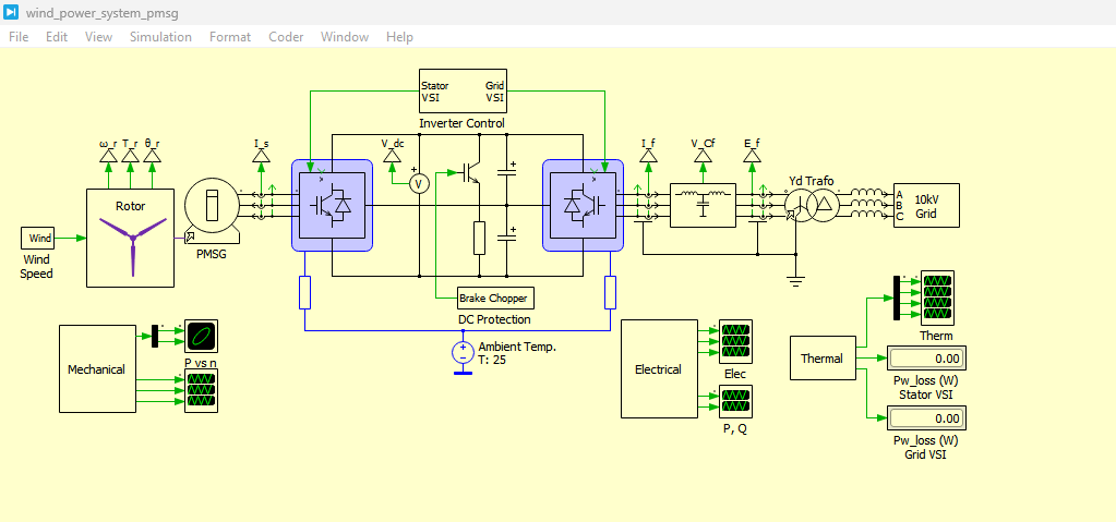
Figure 2: Wind Power PMSG Model developed in PLECS Simulation
The wind turbine converts aerodynamic energy into mechanical torque, which is transmitted directly to the PMSG rotor through an elastic shaft model. The electrical power generated by the PMSG is processed by the machine-side converter, transferred through a regulated DC-link, and delivered to the utility grid via the grid-side converter, an LCL filter, and a step-up transformer. The modular architecture allows each subsystem to be analyzed individually while maintaining realistic interaction with the remaining components.
B. Mechanical Drivetrain Model
The mechanical subsystem represents the dynamic characteristics of a direct-drive wind turbine. It includes individual blade inertias, hub inertia, shaft stiffness, torsional damping, and elastic coupling between rotating components. Unlike simplified rigid-shaft models, the proposed drivetrain accurately captures torsional oscillations that occur during wind fluctuations and electrical disturbances.
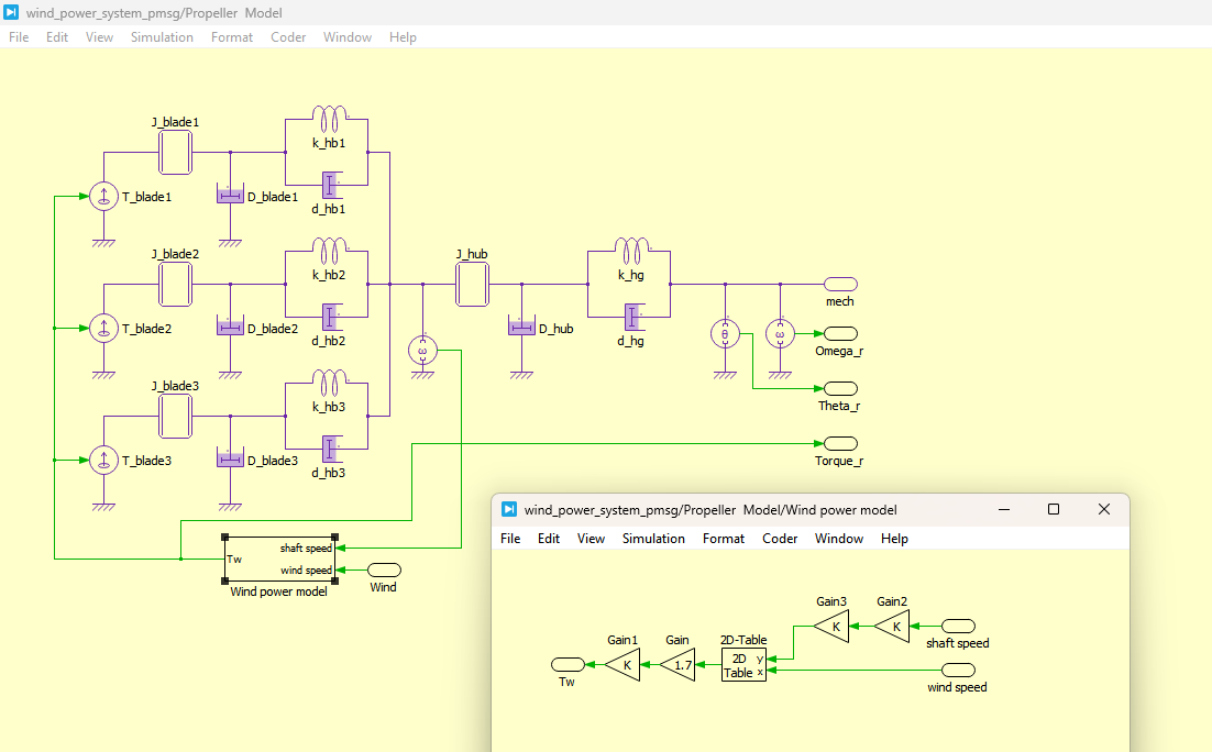
Figure 3: Propeller Model with Wind Power Model developed in PLECS
You can download the Project files here: Download files now. (You must be logged in).
Figure 3 presents the propeller model integrated with the wind power model developed in PLECS. This figure illustrates the aerodynamic-to-mechanical energy conversion process, where wind speed and rotor dynamics determine the generated mechanical torque. The model captures the nonlinear relationship between wind input and turbine output, enabling realistic simulation of wind energy extraction under varying environmental conditions.
The aerodynamic torque is obtained from a two-dimensional lookup table relating wind speed and rotor speed. This approach enables realistic turbine behavior under varying environmental conditions without requiring complex aerodynamic calculations during simulation. The mechanical model also allows investigation of resonance phenomena and transient shaft dynamics following sudden load or grid disturbances.
C. Permanent Magnet Synchronous Generator Model
The PMSG is modeled as a three-phase synchronous machine directly connected to the machine-side NPC converter. Permanent magnets provide constant excitation flux, eliminating rotor excitation losses and improving conversion efficiency. The generator is designed for variable-speed operation, allowing the rotor speed to follow the optimum operating point determined by the MPPT controller.
Electrical quantities including stator currents, terminal voltages, electromagnetic torque, rotor position, and rotational speed are continuously monitored throughout the simulation. These measured signals are simultaneously used for converter control, system protection, and performance evaluation.
D. Three-Level NPC Converter
A three-level Neutral-Point Clamped back-to-back converter is employed to interface the generator with the utility grid. The converter consists of two identical three-phase voltage source converters connected through a common DC-link capacitor bank.
The machine-side converter regulates generator torque and rotor speed, whereas the grid-side converter maintains constant DC-link voltage and transfers active power to the electrical network. The NPC topology provides three discrete output voltage levels, thereby reducing harmonic distortion, lowering voltage stress on semiconductor devices, and improving converter efficiency compared with conventional two-level converters.
The switching pulses are generated using three-level Space Vector Pulse Width Modulation (SVPWM). The modulation strategy optimizes DC-link voltage utilization while producing nearly sinusoidal output voltages with reduced switching harmonics. Depending on the selected modulation sequence, the converter may prioritize either reduced switching losses or improved harmonic performance.
E. Inverter Control System
Both Inverter stages employ cascaded vector control operating in the synchronous rotating dq reference frame.
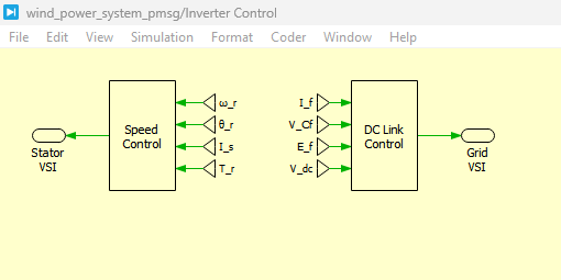
Figure 4: Inverter Control model which contains Speed control and DC Link Control system in PLECS
Figure 4 presents the inverter control model, which includes both the speed control loop and DC-link voltage control system implemented in PLECS. This control structure manages the overall operation of the back-to-back converter by regulating generator speed on the machine side and maintaining stable DC-link voltage on the grid side. The coordination between both controllers ensures smooth power transfer and stable system performance.
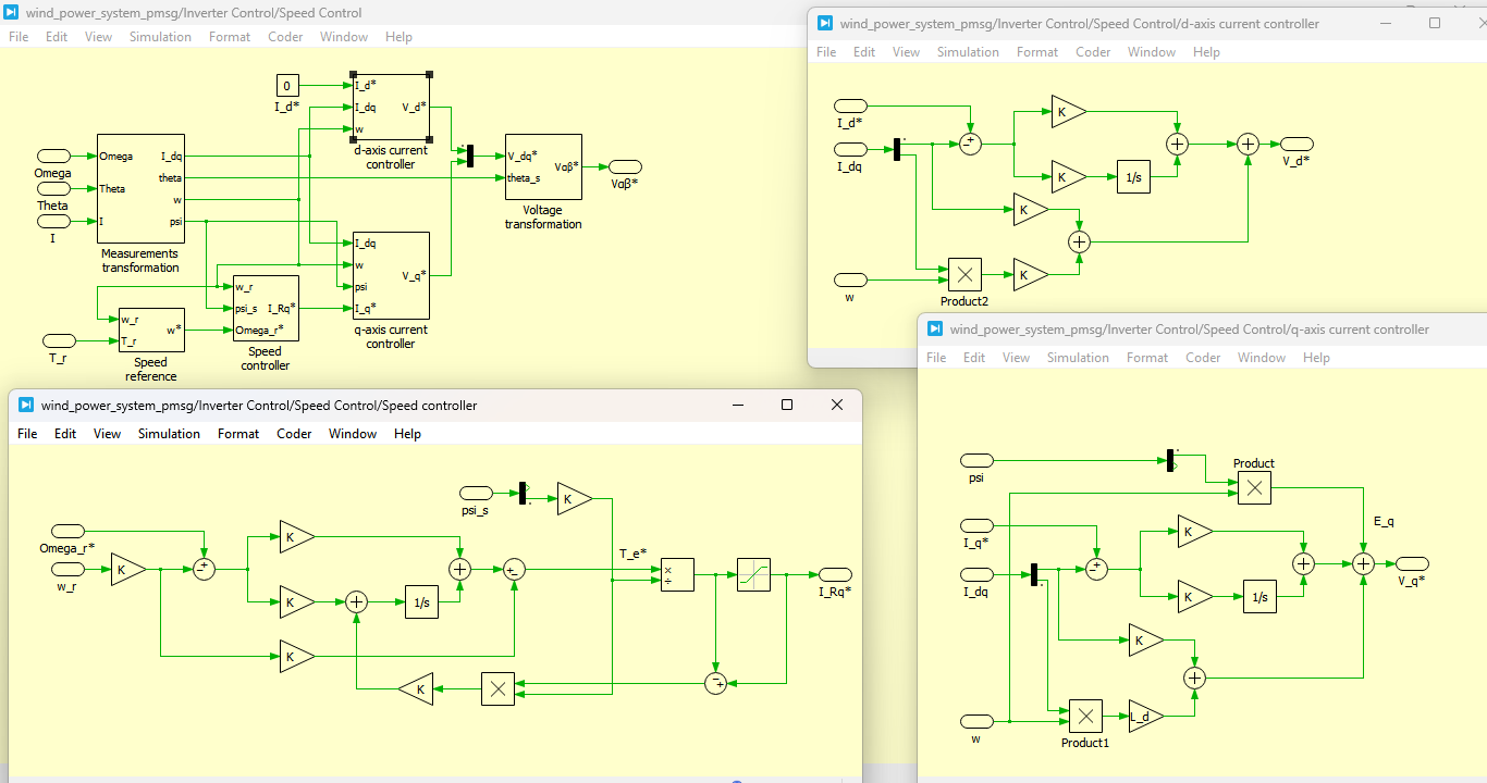
Figure 5: Speed Control system which contains speed controller circuit, d-axis current controller and q-axis current controller circuit
Figure 5 presents the speed control system consisting of the outer speed controller and inner current control loops, including d-axis and q-axis current controllers. The speed controller generates reference torque based on rotor speed error, while the dq current controllers regulate electromagnetic torque production. This cascaded structure ensures fast dynamic response and accurate tracking of the desired rotor speed.
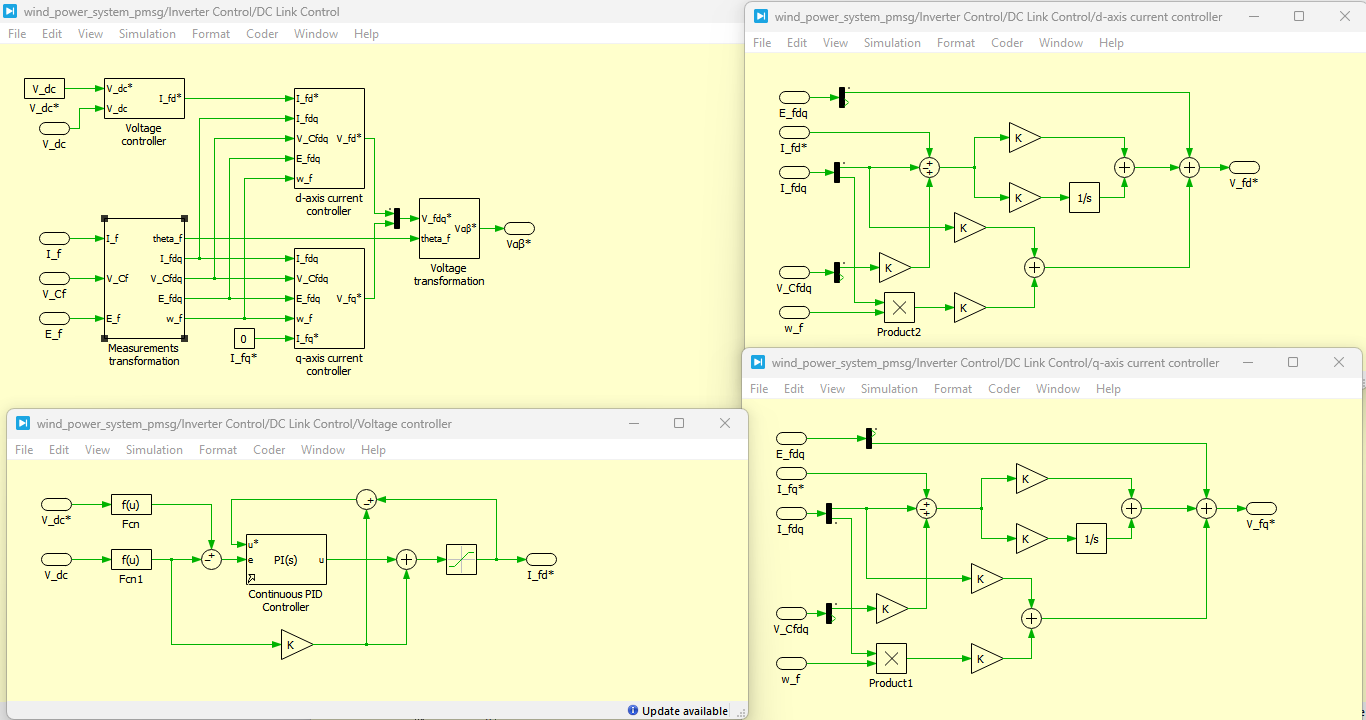
Figure 6: DC Link Controller with Voltage controller, d-axis controller and q-axis controller circuit in PLECS
Figure 6 presents the DC-link controller, which includes the voltage regulation loop along with d-axis and q-axis control components. The DC-link voltage controller maintains a constant DC bus level despite variations in wind speed and grid conditions. The coordinated dq-axis current regulation ensures stable power balance between the machine-side and grid-side converters.
For the machine-side converter, the outer PI controller regulates generator speed according to the reference produced by the MPPT algorithm. The resulting torque command is converted into reference current components for the inner current control loop. Independent regulation of d-axis and q-axis currents ensures rapid dynamic response while maintaining high conversion efficiency.
The grid-side converter utilizes a similar cascaded control structure. The outer voltage controller maintains the DC-link voltage at approximately 1500 V by regulating active current injection into the utility grid. The inner current controller independently regulates active and reactive current components, allowing stable power transfer while supporting grid voltage requirements. Feed-forward compensation, active damping, and anti-windup techniques are incorporated to enhance controller stability during transient operating conditions.
F. Maximum Power Point Tracking Implementation
Maximum Power Point Tracking is implemented using the Perturb-and-Observe algorithm available within the PLECS State Machine environment. The controller periodically perturbs the generator speed and evaluates the resulting electrical power. Depending on whether power increases or decreases, the controller adjusts the reference rotor speed accordingly until the optimum operating point is reached.
The algorithm effectively tracks the maximum power point during gradual wind speed variations from approximately 6 m/s to 12 m/s. Although rapid wind gusts may temporarily reduce tracking accuracy, the controller successfully restores optimum operation after short transient intervals.
G. Thermal Modeling
One of the major advantages of the developed simulation model is the inclusion of detailed electro-thermal analysis. Manufacturer-based thermal descriptions are assigned to each IGBT and anti-parallel diode module within the switched converter configuration. During every switching interval, instantaneous conduction losses and switching losses are calculated automatically.
The thermal network determines semiconductor junction temperatures using thermal impedance data supplied by the device manufacturer. Ambient temperature and cooling system characteristics are also included to represent realistic converter operating conditions. The thermal model enables investigation of converter efficiency, device heating, cooling performance, and expected semiconductor reliability throughout the simulation.
H. Simulation Scenarios
Several operating conditions are investigated to evaluate the overall performance of the proposed wind power system.
Initially, the system operates under steady-state conditions to verify stable generator operation, accurate DC-link voltage regulation, and balanced three-phase grid currents. Subsequently, a temporary voltage sag is introduced on the 10 kV utility network to evaluate the transient response of the converter controllers and the fault ride-through capability of the complete system.
Finally, the wind speed is gradually increased and decreased over a predefined operating range to assess the effectiveness of the MPPT controller. During these tests, rotor speed, generated power, electromagnetic torque, DC-link voltage, active power, reactive power, semiconductor losses, and junction temperatures are continuously monitored.
The comprehensive PLECS simulation model therefore provides an effective platform for evaluating the electrical, mechanical, control, and thermal performance of the proposed grid-connected PMSG wind energy conversion system before practical hardware implementation. The simulation results presented in the following section demonstrate the capability of the developed system to achieve efficient power conversion, stable grid integration, and reliable operation under both normal and disturbed operating conditions.
VI. Results and Discussion
The proposed 2 MW Permanent Magnet Synchronous Generator (PMSG)-based wind energy conversion system was evaluated using the PLECS simulation environment under various operating conditions to investigate its electrical, mechanical, thermal, and control performance. The simulation model integrates the wind turbine, mechanical drivetrain, three-level Neutral-Point Clamped (NPC) back-to-back converter, Maximum Power Point Tracking (MPPT) algorithm, vector control strategy, and thermal models of semiconductor devices. The obtained simulation results demonstrate the effectiveness of the proposed system in achieving stable operation, efficient energy conversion, and reliable grid integration.
A. Steady-State Performance
Initially, the wind power system was operated under steady-state conditions with a constant wind speed to verify the effectiveness of the implemented control strategy. During this operating condition, the Permanent Magnet Synchronous Generator successfully converted mechanical energy into electrical power while maintaining stable rotor speed and electromagnetic torque. The machine-side converter accurately regulated the generator current components, allowing smooth torque production with negligible oscillations.
The grid-side converter maintained the DC-link voltage at its specified reference value throughout the simulation despite continuous power transfer between the generator and the utility grid. Balanced three-phase output currents with nearly sinusoidal waveforms were obtained, confirming the effectiveness of the three-level NPC converter and the Space Vector Pulse Width Modulation (SVPWM) strategy in minimizing harmonic distortion.
Furthermore, the active power generated by the wind turbine closely matched the electrical power delivered to the utility grid after accounting for converter losses. Reactive power remained near its desired reference value, demonstrating successful independent control of active and reactive power components.
B. Dynamic Response During Grid Voltage Sag
To evaluate the transient performance of the proposed system, a temporary voltage sag was introduced at the medium-voltage utility grid. This disturbance represents one of the most critical operating conditions encountered in practical power systems.
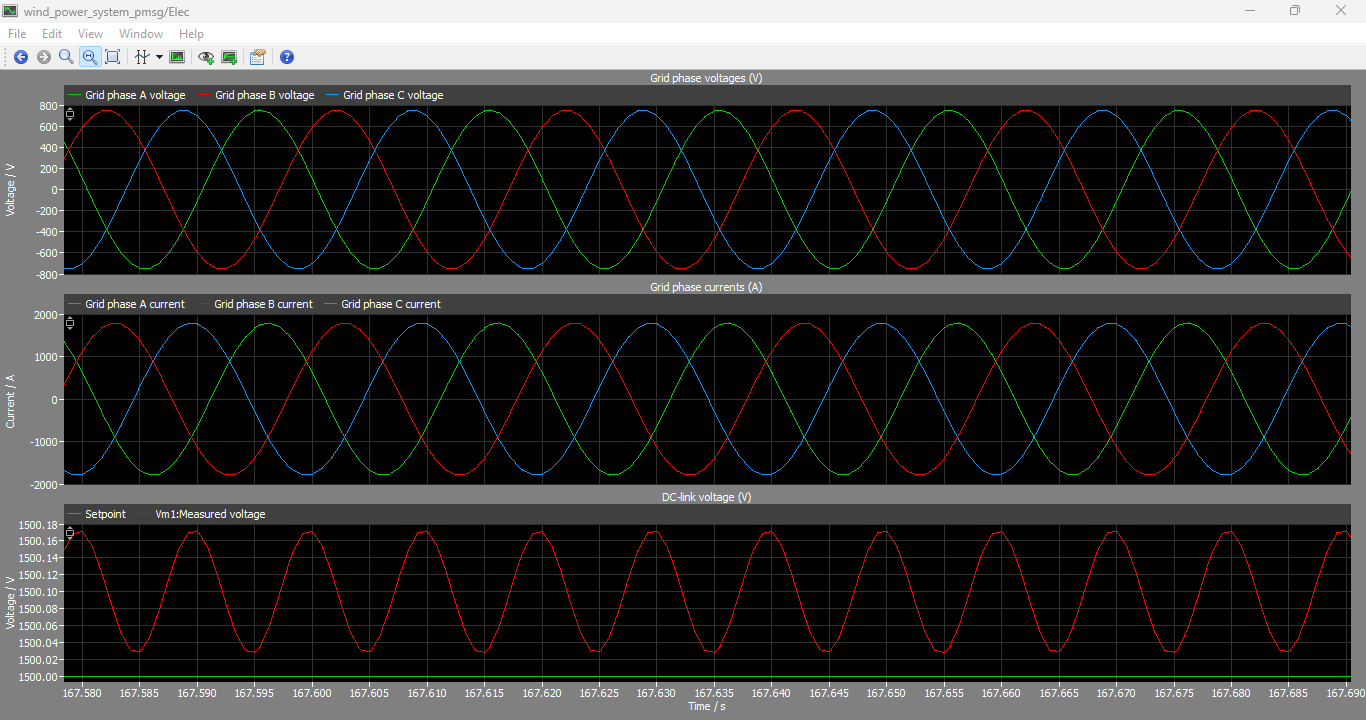
Figure 7: Grid Phase Voltages, Currents and DC link voltages output graphs
You can download the Project files here: Download files now. (You must be logged in).
Figure 7 presents the grid-side electrical waveforms, including grid phase voltages, grid currents, and DC-link voltage response. These results demonstrate that the grid-side converter successfully injects balanced sinusoidal currents into the grid while maintaining a stable DC-link voltage. The waveform quality confirms effective harmonic suppression and proper synchronization with the utility grid.
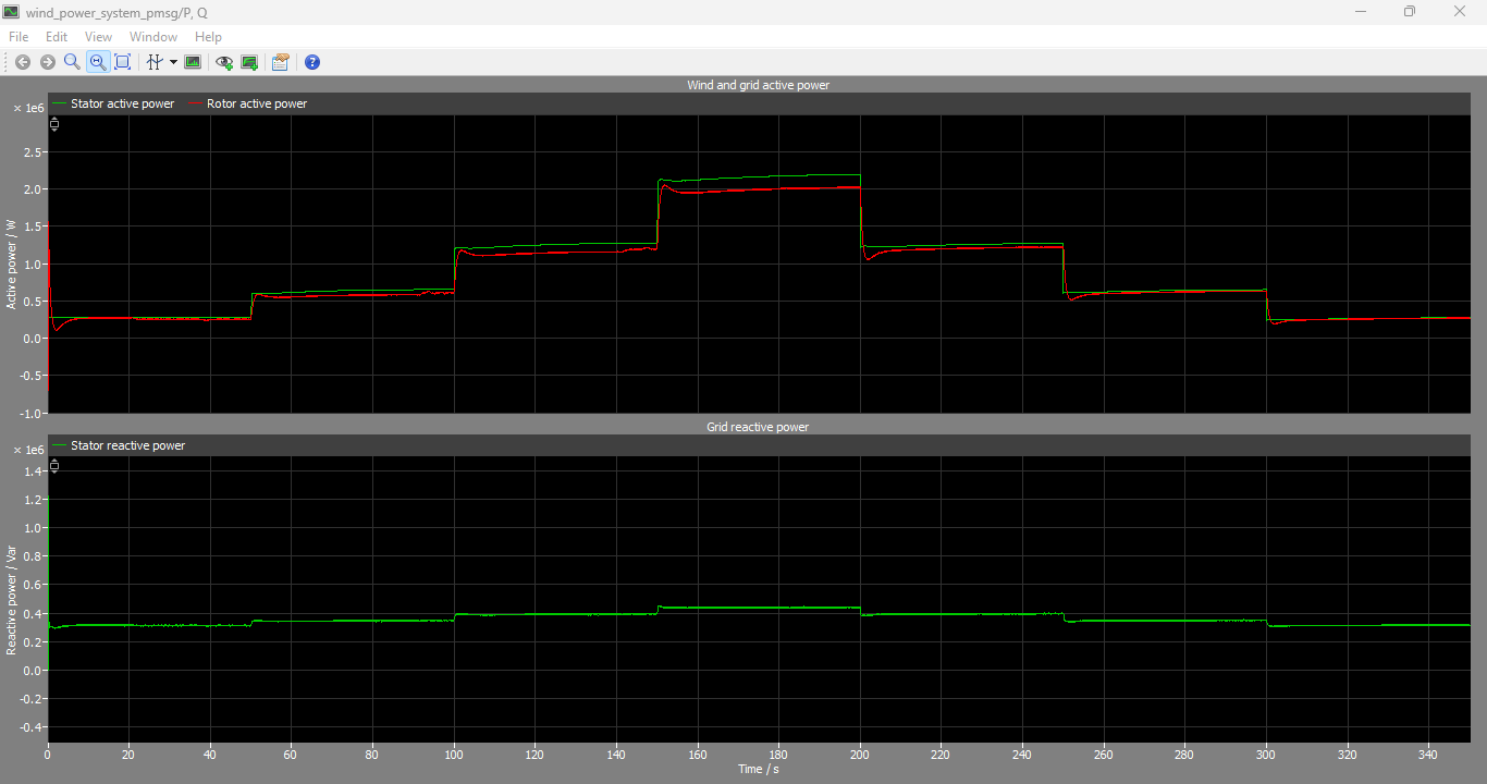
Figure 8: Wind and Grid active power and Grid reactive power output graphs
Figure 8 presents the active and reactive power exchange between the wind energy system and the grid. The results show that active power closely follows wind energy variations, while reactive power is independently controlled to support grid stability. This decoupled control highlights the effectiveness of the vector control strategy used in the grid-side converter.
Immediately after the voltage sag occurred, transient oscillations appeared in both electrical and mechanical variables due to the sudden reduction in grid voltage. However, the cascaded vector control strategy effectively compensated for the disturbance by rapidly adjusting converter current references. Although short-duration fluctuations were observed in generator torque, DC-link voltage, and grid current, the controller maintained overall system stability throughout the fault period.
The DC-link voltage experienced only a limited deviation from its reference value before rapidly recovering after the fault was cleared. Similarly, generator speed remained stable without excessive overshoot, indicating satisfactory coordination between the machine-side and grid-side converters. Following voltage restoration, the generated active power gradually returned to its pre-fault operating level while reactive power regulation remained stable.
These observations demonstrate that the proposed control strategy provides effective fault ride-through capability and satisfies the operational requirements of modern grid-connected renewable energy systems.
C. Maximum Power Point Tracking Performance
The performance of the Perturb-and-Observe Maximum Power Point Tracking algorithm was evaluated under gradually varying wind speed conditions. During simulation, the wind speed increased from approximately 6 m/s to 12 m/s and was subsequently reduced to its initial value.
As the wind speed changed, the MPPT controller continuously modified the generator speed reference to maintain operation near the optimum power point. After each change in wind velocity, the generator speed required a short adjustment period before converging to its new operating point. Consequently, the generated electrical power increased progressively with increasing wind speed and decreased correspondingly when the wind velocity was reduced.
The simulation results indicate that the implemented MPPT algorithm successfully tracked the maximum available wind power throughout the operating range. Only minor transient oscillations were observed immediately after each wind speed variation, which quickly disappeared as the controller converged toward the optimum operating condition. These results confirm the suitability of the Perturb-and-Observe algorithm for practical wind energy applications involving gradual atmospheric variations.
D. Converter Performance
The three-level Neutral-Point Clamped converter demonstrated excellent electrical performance during both steady-state and transient operating conditions. Compared with conventional two-level converters, the multilevel topology produced output voltages with lower harmonic distortion and smoother current waveforms.
The implemented Space Vector Pulse Width Modulation strategy generated balanced switching patterns for all converter legs while effectively utilizing the available DC-link voltage. Reduced voltage stress across individual semiconductor devices contributed to lower switching losses and improved converter efficiency.
Throughout the simulation, the grid-side converter maintained stable synchronization with the utility network while accurately regulating active and reactive current components. The coordinated operation of both converter stages enabled continuous energy transfer from the wind turbine to the electrical grid without instability or significant power fluctuations.
E. Mechanical System Analysis
The detailed mechanical drivetrain model successfully represented the elastic coupling between the turbine blades, hub, and generator shaft. Under normal operating conditions, mechanical oscillations remained minimal due to the damping incorporated within the shaft model.
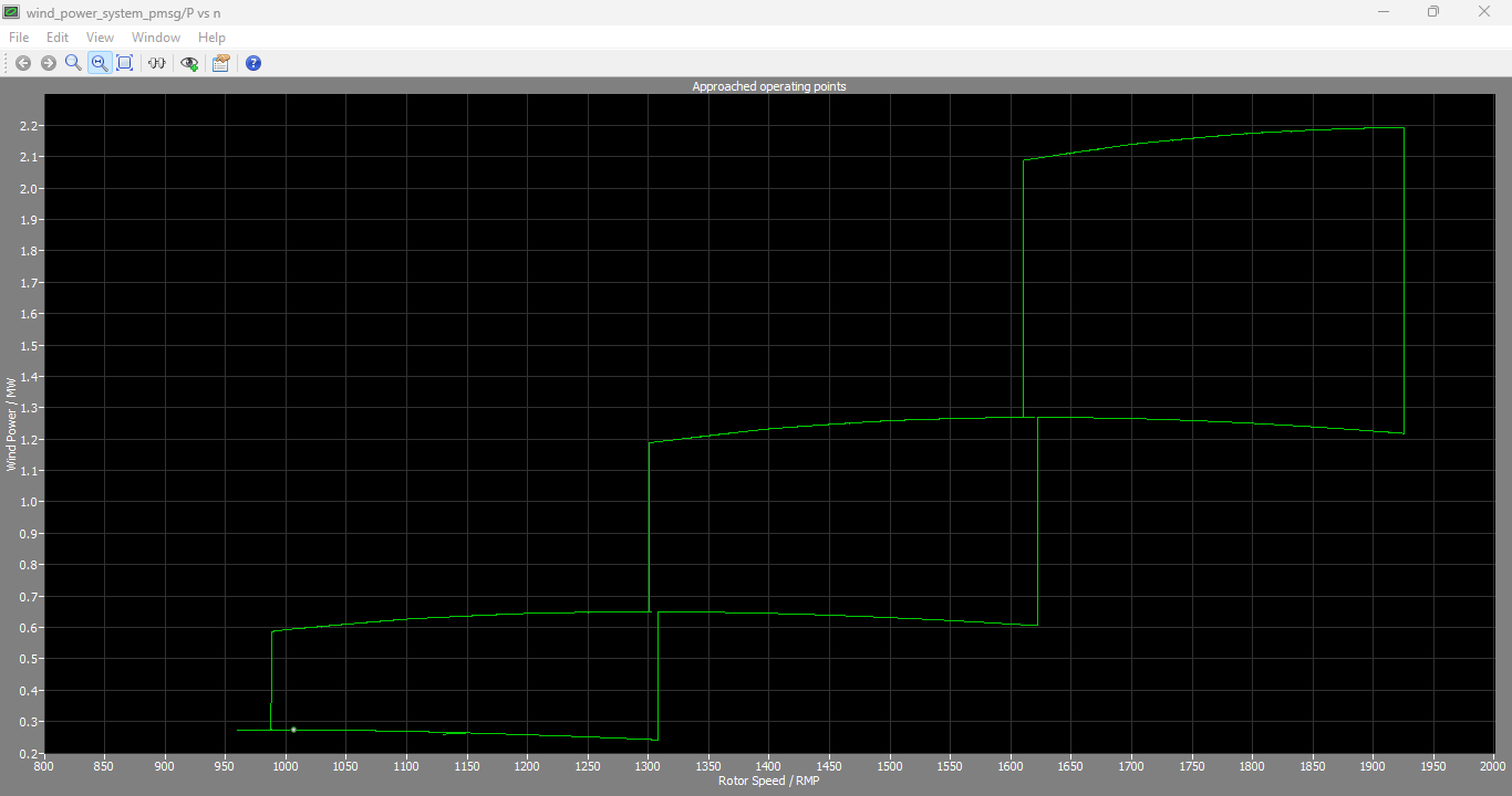
Figure 9: Mechanical Wind Power VS Rotor Speed output graph
Figure 9 presents the relationship between mechanical wind power and rotor speed. The curve illustrates the maximum power extraction point for different rotor speeds under varying wind conditions. This relationship is essential for implementing the Maximum Power Point Tracking (MPPT) algorithm, ensuring optimal turbine operation.
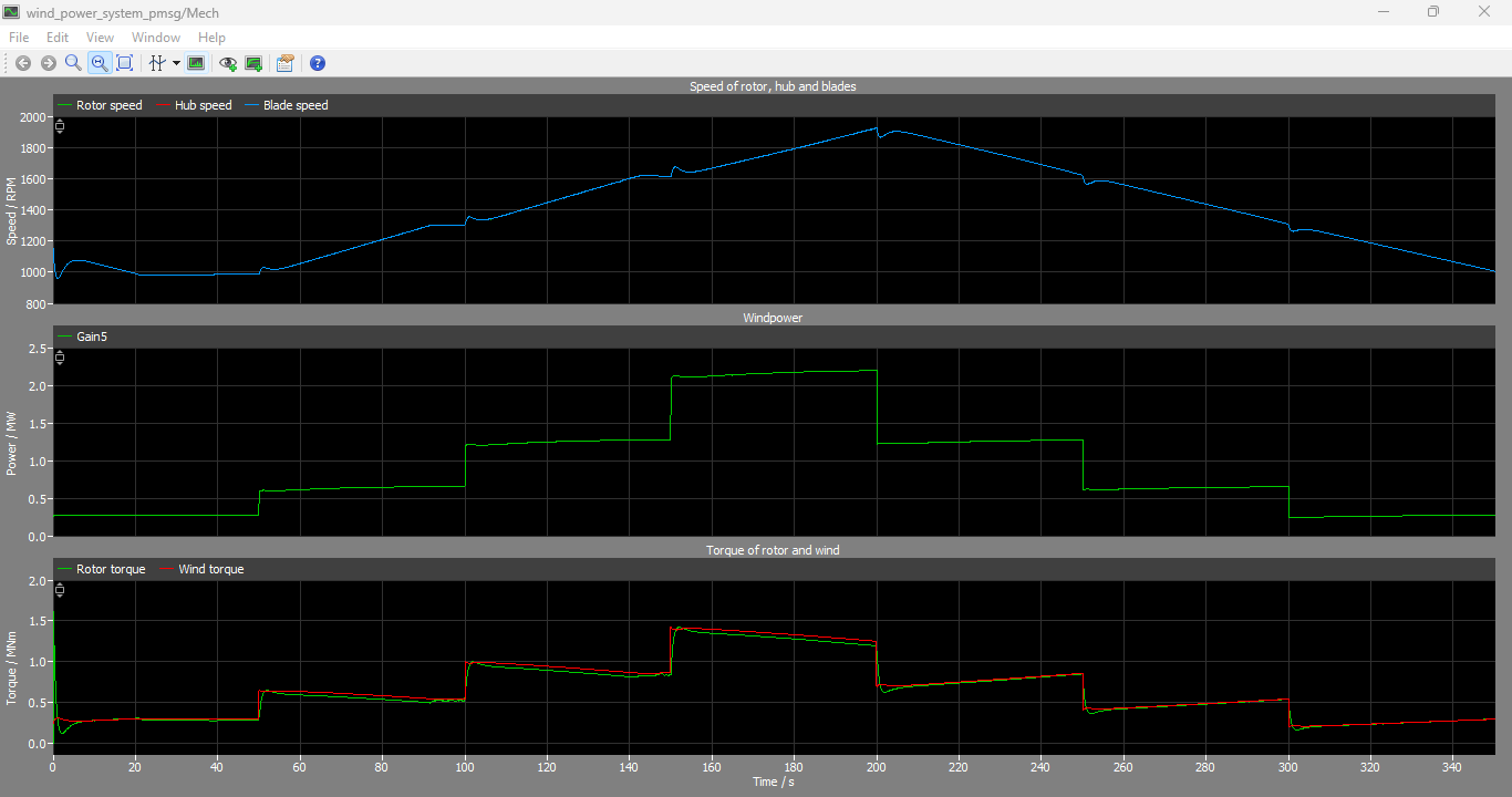
Figure 10: Rotor Speed, Wind Power and Torque of rotor and wind output graphs
Figure 10 presents the dynamic behavior of rotor speed, wind power, and electromagnetic torque over time. The results show how the system responds to changes in wind speed, with the rotor speed adjusting accordingly to maintain optimal energy extraction. The torque variation reflects the controller’s effort to balance mechanical input and electrical output.
Following grid disturbances and changes in wind speed, temporary torsional oscillations appeared within the drivetrain. These oscillations gradually decayed as mechanical damping dissipated the stored vibration energy. The simulation confirms that the direct-drive PMSG configuration exhibits satisfactory mechanical stability while eliminating gearbox-related losses and maintenance requirements.
Rotor speed closely followed the reference generated by the MPPT controller throughout the simulation. Smooth acceleration and deceleration characteristics were observed without excessive overshoot, demonstrating effective coordination between the mechanical subsystem and the generator control system.
F. Thermal Performance
The switched converter model enabled detailed investigation of semiconductor thermal behavior. Conduction losses and switching losses of each IGBT and anti-parallel diode were continuously calculated using manufacturer-provided thermal descriptions.
The simulation results indicate that semiconductor junction temperatures increased gradually as converter loading increased. Nevertheless, all junction temperatures remained within acceptable operating limits throughout the simulated operating conditions due to the effectiveness of the implemented cooling system.
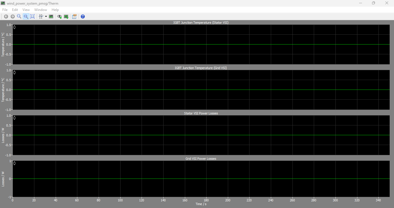
Figure 11: IGBT Junction Temperature (Stator VSI), (Grid VSI), (Stator VSI Power Losses) and (Grid VSI Power Losses) output graphs
You can download the Project files here: Download files now. (You must be logged in).
Figure 11 presents the thermal performance of the power electronic devices, including IGBT junction temperature and power losses for both the stator-side and grid-side voltage source inverters (VSI). The results indicate that junction temperatures remain within safe operating limits, while power losses vary with load conditions. This confirms the effectiveness of the thermal management system and switching strategy.
Switching losses were found to vary according to converter switching frequency and operating current, whereas conduction losses primarily depended on converter loading. The thermal impedance network accurately represented heat transfer between semiconductor junctions and the cooling system, enabling realistic estimation of device temperatures.
Thermal analysis confirms that the selected converter topology provides satisfactory efficiency and reliable long-term operation for high-power wind energy applications.
G. Overall Performance Evaluation
The integrated simulation results demonstrate that the proposed wind energy conversion system successfully combines efficient energy extraction, stable converter operation, intelligent control, and reliable thermal performance within a unified PLECS simulation environment.
The Permanent Magnet Synchronous Generator provided high-efficiency variable-speed operation while the three-level NPC converter ensured high-quality power conversion with reduced harmonic distortion and lower semiconductor voltage stress. The cascaded vector control strategy maintained stable generator speed, DC-link voltage, active power, and reactive power under both steady-state and transient conditions. Furthermore, the Perturb-and-Observe Maximum Power Point Tracking algorithm effectively maximized wind energy utilization over a wide operating range.
Overall, the simulation results verify that the proposed system offers excellent dynamic performance, reliable grid integration capability, effective thermal management, and high operational efficiency, making it a suitable solution for modern medium-voltage renewable energy generation systems.
VII. Conclusion
This paper presented the modeling, simulation, and performance evaluation of a 2 MW grid-connected wind energy conversion system employing a Permanent Magnet Synchronous Generator (PMSG) using the PLECS simulation platform. The developed model integrated the electrical power conversion system, mechanical drivetrain, thermal behavior of semiconductor devices, and advanced converter control strategies within a unified simulation environment. Such an integrated approach enabled comprehensive analysis of system performance under steady-state, dynamic, and fault operating conditions.
The proposed system utilized a three-level Neutral-Point Clamped (NPC) back-to-back converter to interface the PMSG with the medium-voltage electrical grid. Compared with conventional two-level converter topologies, the NPC converter demonstrated improved voltage waveform quality, lower harmonic distortion, reduced semiconductor voltage stress, and enhanced converter efficiency. The implementation of Space Vector Pulse Width Modulation (SVPWM) further improved DC-link voltage utilization while maintaining balanced three-phase output voltages and currents.
A cascaded vector control strategy was successfully implemented for both the machine-side and grid-side converters. The generator-side controller accurately regulated rotor speed and electromagnetic torque, while the grid-side controller maintained stable DC-link voltage and independently controlled active and reactive power flow. The coordinated operation of both converter stages ensured smooth energy transfer from the wind turbine to the electrical grid during both normal operation and transient disturbances.
The Perturb-and-Observe Maximum Power Point Tracking (MPPT) algorithm effectively adjusted the generator operating speed according to changing wind conditions, enabling continuous extraction of maximum available wind energy. Simulation results confirmed that the controller rapidly converged toward the optimum operating point following gradual wind speed variations while maintaining stable generator performance throughout the operating range.
Thermal analysis incorporated within the switched converter model provided valuable information regarding semiconductor switching losses, conduction losses, and junction temperature variations. The obtained results demonstrated that the implemented cooling system maintained device temperatures within safe operating limits under all investigated operating conditions, thereby improving converter reliability and expected operational lifetime.
The simulation study further demonstrated satisfactory dynamic performance during grid voltage sag conditions. Although temporary oscillations appeared immediately after the disturbance, the proposed control strategy rapidly restored stable operation by regulating generator torque, DC-link voltage, and grid current components. The successful recovery of system variables verified the robustness of the implemented control algorithms and confirmed the suitability of the proposed converter configuration for modern grid-connected renewable energy applications.
Overall, the integrated PLECS simulation successfully demonstrated that combining a Permanent Magnet Synchronous Generator, a three-level Neutral-Point Clamped converter, cascaded vector control, Perturb-and-Observe Maximum Power Point Tracking, and electro-thermal modeling provides a highly efficient and reliable solution for large-scale wind energy conversion systems. The proposed model offers excellent power quality, stable dynamic response, efficient energy extraction, and improved thermal performance while satisfying practical grid integration requirements.
Future research may focus on implementing advanced intelligent Maximum Power Point Tracking techniques such as artificial neural networks, fuzzy logic control, or reinforcement learning to improve energy capture under rapidly changing wind conditions. Additional investigations may also consider battery energy storage integration, predictive converter control, grid-forming inverter operation, fault diagnosis techniques, and hardware-in-the-loop validation for practical implementation in next-generation smart grid applications.
References
[1] J. S. Thongam and M. Ouhrouche, “MPPT control methods in wind energy conversion systems,” Fundamental and Advanced Topics in Wind Power, vol. 1, pp. 339-360, 2011.
[2] T. Ackermann, Wind Power in Power Systems, 2nd ed. Chichester, U.K.: Wiley, 2012.
[3] S. Heier, Grid Integration of Wind Energy Conversion Systems, 3rd ed. Hoboken, NJ, USA: Wiley, 2014.
[4] B. Wu, Y. Lang, N. Zargari, and S. Kouro, Power Conversion and Control of Wind Energy Systems. Hoboken, NJ, USA: Wiley, 2011.
[5] R. Teodorescu, M. Liserre, and P. Rodriguez, Grid Converters for Photovoltaic and Wind Power Systems. Chichester, U.K.: Wiley, 2011.
[6] J. Rodriguez, J. Lai, and F. Z. Peng, “Multilevel inverters: A survey of topologies, controls, and applications,” IEEE Transactions on Industrial Electronics, vol. 49, no. 4, pp. 724-738, Aug. 2002.
[7] B. K. Bose, Modern Power Electronics and AC Drives. Upper Saddle River, NJ, USA: Prentice Hall, 2002.
[8] H. Abu-Rub, M. Malinowski, and K. Al-Haddad, Power Electronics for Renewable Energy Systems. Hoboken, NJ, USA: Wiley, 2014.
[9] N. Mohan, T. M. Undeland, and W. P. Robbins, Power Electronics: Converters, Applications, and Design, 3rd ed. Hoboken, NJ, USA: Wiley, 2003.
[10] F. Blaabjerg, M. Liserre, and K. Ma, “Power electronics converters for wind turbine systems,” IEEE Transactions on Industry Applications, vol. 48, no. 2, pp. 708-719, 2012.
[11] P. C. Krause, O. Wasynczuk, S. D. Sudhoff, and S. Pekarek, Analysis of Electric Machinery and Drive Systems, 3rd ed. Hoboken, NJ, USA: Wiley, 2013.
[12] D. W. Novotny and T. A. Lipo, Vector Control and Dynamics of AC Drives. Oxford, U.K.: Oxford University Press, 1996.
[13] E. Rashid, Power Electronics Handbook, 4th ed. Oxford, U.K.: Butterworth-Heinemann, 2018.
[14] F. Blaabjerg and D. M. Ionel, Renewable Energy Devices and Systems with Simulations in MATLAB and ANSYS. Boca Raton, FL, USA: CRC Press, 2017.
[15] Plexim GmbH, PLECS User Manual and Demo Models, Version 4.7.1, Zurich, Switzerland, 2023.
[16] A. Yazdani and R. Iravani, Voltage-Sourced Converters in Power Systems. Hoboken, NJ, USA: Wiley, 2010.
[17] J. G. Slootweg and W. L. Kling, “Impacts of distributed generation on power system transient stability,” IEEE Power Engineering Society Summer Meeting, vol. 2, pp. 862-867, 2002.
[18] U. Drofenik and J. W. Kolar, “A general scheme for calculating switching and conduction losses of power semiconductors,” International Power Electronics Conference, pp. 297-303, 2005.
[19] H. Wang, M. Liserre, and F. Blaabjerg, “Toward reliable power electronics: Challenges, design tools, and opportunities,” IEEE Industrial Electronics Magazine, vol. 7, no. 2, pp. 17-26, Jun. 2013.
[20] F. Blaabjerg, Y. Yang, D. Yang, and X. Wang, “Distributed power-generation systems and protection,” Proceedings of the IEEE, vol. 105, no. 7, pp. 1311-1331, Jul. 2017.
[21] J. F. Manwell, J. G. McGowan, and A. L. Rogers, Wind Energy Explained: Theory, Design and Application, 2nd ed. Chichester, U.K.: Wiley, 2010.
You can download the Project files here: Download files now. (You must be logged in).










Responses