

Modeling and Control Performance Analysis of a Three-Phase Vienna Rectifier Using Hysteresis Current Control in PLECS

Author: Waqas Javaid
Abstract
The increasing demand for high-efficiency AC-DC power conversion systems in industrial power supplies, renewable energy interfaces, electric vehicle charging systems, and telecommunication infrastructure has accelerated the adoption of multilevel rectifier topologies. Among these converters, the Vienna Rectifier has emerged as a preferred solution due to its high efficiency, reduced semiconductor stress, low harmonic distortion, and capability to achieve near-unity power factor. This paper presents the modeling, simulation, and performance evaluation of a three-phase Vienna Rectifier controlled using a hysteresis current controller in the PLECS simulation environment. The implemented system operates at an output voltage of 700V and delivers approximately 12.25kW of output power. The control architecture consists of cascaded loops including a DC-link voltage controller, a neutral-point voltage balancing controller, and a hysteresis current controller. The simulation investigates system performance during startup and under asymmetrical load disturbances. Results demonstrate effective regulation of the DC output voltage, balanced capacitor voltages, sinusoidal input current shaping, and rapid dynamic response under load imbalance conditions. The study confirms the suitability of hysteresis-controlled Vienna Rectifiers for high-performance power conversion applications requiring high efficiency and improved power quality.
I. Introduction
Modern power electronic systems increasingly require high-power-density AC-DC converters capable of meeting stringent efficiency and power quality standards. Conventional diode rectifiers suffer from significant drawbacks including poor power factor, excessive harmonic distortion, and limited controllability. As international standards such as IEEE 519 impose stricter harmonic limits, advanced rectifier topologies have become essential for industrial and commercial applications.
The Vienna Rectifier, first introduced by Kolar and Zach, represents an important advancement in three-phase power conversion technology [1]. It is a three-phase, three-switch, three-level unidirectional pulse-width-modulated rectifier designed to achieve high efficiency while maintaining excellent input current quality. Compared with conventional six-switch active front-end converters, the Vienna Rectifier uses fewer active semiconductor devices, resulting in reduced switching losses and lower implementation cost.
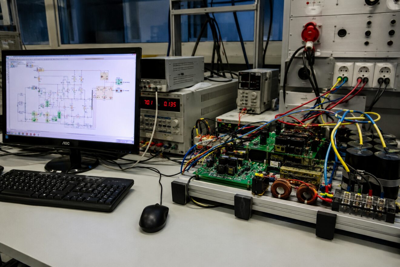
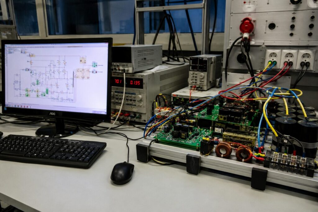
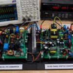
Figure 1: Laboratory setup illustrating the development and validation environment of a three-phase Vienna Rectifier controlled using a hysteresis current control strategy.
Figure 1 presents the experimental and simulation environment utilized for the design and analysis of the Vienna Rectifier system. The workstation displays the converter model developed in PLECS, while the surrounding laboratory equipment represents a typical power electronics research platform used for testing high-power AC-DC conversion systems. Such integrated simulation and hardware environments enable detailed investigation of converter behavior, control algorithm validation, power quality assessment, and dynamic performance evaluation under various operating conditions. The Vienna Rectifier topology studied in this paper employs cascaded voltage and current control loops to achieve regulated DC output voltage, sinusoidal input currents, and balanced DC-link capacitor voltages. The use of PLECS facilitates accurate modeling of both the power circuit and control system, providing an efficient platform for analyzing transient and steady-state responses before practical implementation.
The topology has become particularly attractive in telecommunications power supplies, electric vehicle charging stations, aerospace power systems, renewable energy interfaces, and industrial motor drives. Its three-level structure allows reduced voltage stress across semiconductor devices while simultaneously lowering electromagnetic interference and improving overall efficiency [2].
A critical challenge associated with Vienna Rectifiers is maintaining balanced voltages across the split DC-link capacitors. Under asymmetrical loading conditions, unequal capacitor voltages may develop, leading to performance degradation and potential reliability issues. Therefore, advanced control methods are necessary to ensure proper neutral-point voltage balancing.
This paper investigates a Vienna Rectifier controlled through a hysteresis current controller implemented in PLECS. The study evaluates the converter’s dynamic behavior during startup and under load disturbances while emphasizing DC voltage regulation, current shaping, and neutral-point voltage balancing.
II. Vienna Rectifier Topology
The Vienna Rectifier is a three-phase, three-switch, three-level boost-type rectifier capable of unidirectional power flow. The topology consists of:
- Three bidirectional switching cells
- Input boost inductors
- A split DC-link capacitor bank
- Diode bridge arrangement
- Control circuitry
The converter receives energy from a three-phase AC source and delivers regulated DC power to the load.
One of the primary advantages of the Vienna Rectifier is the reduced voltage stress imposed on switching devices. Each switch experiences approximately half of the total DC-link voltage due to the three-level configuration. Consequently, lower-rated devices can be used while maintaining high power handling capability.
The simulated system employs:
- Input phase voltage: 327V
- Frequency: 50Hz
- Output voltage: 700V
- Output power: 12.25kW
- Input inductance: 0.3mH
- DC-link capacitors: 2000μF each
The DC-link consists of two capacitors connected in series, creating a neutral point. Ideally, each capacitor should maintain 350V, producing a total DC-link voltage of 700V.
III. Mathematical Modeling
The operation of the Vienna Rectifier can be described using fundamental power balance principles and capacitor dynamics.
The output power delivered to the load can be expressed as [3]:
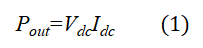
Where:
- Pout = Output power (W)
- Vdc = DC-link voltage (V)
- Idc = Output DC current (A)
Equation (1) describes the relationship between DC voltage and output current. In the presented system, a regulated output voltage of 700V is maintained while supplying approximately 12.25kW to the load.
The capacitor voltage dynamics are represented by [4]:
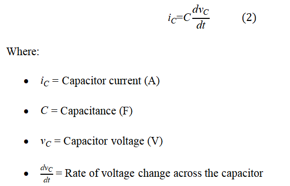
Equation (2) governs the charging and discharging behavior of the split DC-link capacitors. Maintaining equal capacitor voltages is essential for stable Vienna Rectifier operation.
You can download the Project files here: Download files now. (You must be logged in).
IV. Control System Architecture
The control strategy employed in this study consists of three cascaded control loops.
A. DC-Link Voltage Controller
The outermost control loop regulates the total DC-link voltage. A proportional-integral (PI) controller continuously compares the measured DC voltage with the reference value of 700V.
The voltage error is processed by the PI controller to generate the reference current amplitude I*N. This reference determines the amount of power drawn from the AC source.
The primary objective of this controller is:
- Maintain constant output voltage
- Reject load disturbances
- Ensure proper power transfer
B. Neutral-Point Voltage Controller
The split DC-link introduces a neutral point that must remain balanced.
Under asymmetrical loading conditions, unequal capacitor currents can produce voltage imbalance between the upper and lower capacitors. To address this issue, a second PI controller regulates the difference between capacitor voltages.
The controller generates a compensating current reference I*o, which is superimposed onto the phase current references.
The balancing controller provides:
- Neutral-point stabilization
- Equal capacitor voltage distribution
- Improved converter reliability
Without this controller, significant capacitor voltage deviations may occur, leading to increased stress on converter components.
C. Hysteresis Current Controller
The innermost loop utilizes hysteresis current control.
This controller continuously compares the actual input current with the reference current. When the measured current exceeds the upper hysteresis limit, switching actions are initiated to reduce current. Conversely, when the current falls below the lower limit, the switch state changes to increase current.
The controller offers several advantages:
- Fast dynamic response
- Simple implementation
- High robustness
- Excellent tracking performance
Because the Vienna Rectifier operates with alternating polarity in each phase, gate signals must be inverted during the negative half-cycle of the corresponding phase voltage.
This unique switching strategy ensures proper converter operation throughout the AC cycle.
V. PLECS Simulation Model
The complete Vienna Rectifier system was modeled in PLECS 4.3.1 using integrated electrical and control subsystems.
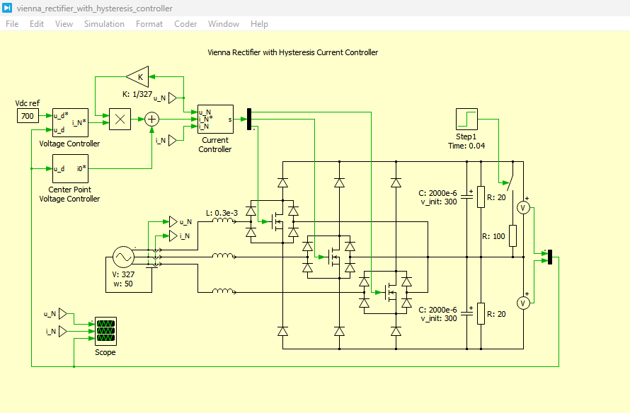
Figure 2: Vienna Rectifier with Hysteresis Current Controller Model development in PLECS Simulation
Figure 2 illustrates the complete Vienna Rectifier model developed in the PLECS simulation environment, integrating both the power circuit and control system components. The model consists of a three-phase AC source, input boost inductors, a three-level Vienna Rectifier topology, split DC-link capacitors, and a resistive load. The control architecture includes a DC-link voltage controller, a center-point voltage balancing controller, and a hysteresis current controller arranged in a cascaded configuration. The DC-link voltage controller regulates the output voltage at 700V, while the center-point controller maintains equal voltage distribution across the two DC-link capacitors. The hysteresis current controller generates the switching signals required for accurate tracking of the reference input currents. This integrated simulation model enables comprehensive analysis of converter dynamics, voltage regulation, current shaping, and neutral-point balancing under various operating conditions.
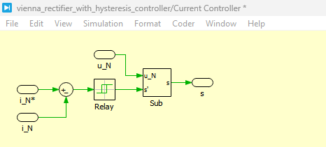
Figure 3: Current Controller Circuit in PLECS
You can download the Project files here: Download files now. (You must be logged in).
Figure 3 presents the hysteresis current controller implemented in the PLECS model. The controller continuously compares the measured three-phase input currents with their corresponding reference currents generated by the outer control loops. Based on the instantaneous current error, the hysteresis controller produces switching commands that maintain the actual current within a predefined hysteresis band around the reference value. When the measured current exceeds the upper limit of the hysteresis band, the switching state changes to decrease the current, whereas a current below the lower limit triggers a switching action that increases the current. This control technique provides rapid dynamic response, excellent current tracking capability, and robust operation under transient conditions. As a result, the input currents remain nearly sinusoidal and closely synchronized with the supply voltages, contributing to high power factor operation and reduced harmonic distortion.
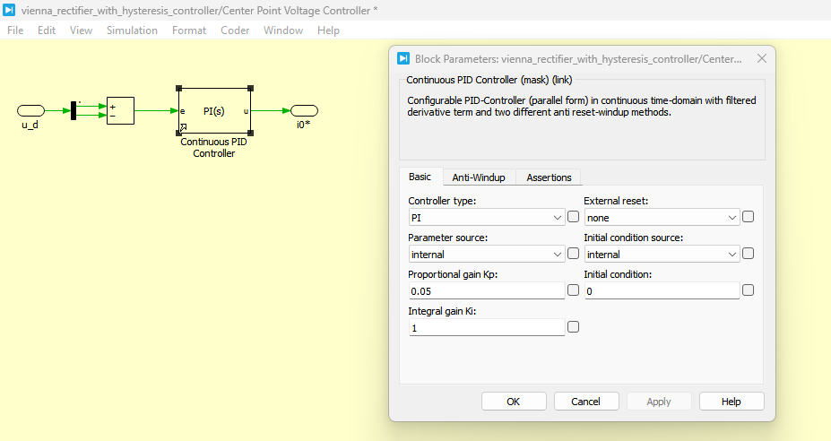
Figure 4: Center Point Voltage Controller with Block parameters in Continuous PID controller in PLECS
Figure 4 shows the implementation of the center-point voltage controller using a continuous PID controller block in PLECS. The purpose of this controller is to maintain balanced voltages across the upper and lower DC-link capacitors, thereby stabilizing the neutral point of the Vienna Rectifier. The controller continuously monitors the voltage difference between the two capacitors and generates a compensating current reference whenever an imbalance occurs. This reference signal is subsequently added to the mains current reference to redistribute the capacitor currents and restore voltage balance. The proportional and integral gains of the PID controller are carefully selected to ensure fast correction of voltage deviations while avoiding excessive oscillations. The center-point voltage controller plays a crucial role during asymmetrical loading conditions, where unequal capacitor charging and discharging could otherwise lead to significant voltage imbalance and reduced converter performance.
The simulation model contains:
Power Circuit Components
- Three-phase AC source
- Input inductors
- Vienna Rectifier switching network
- Split DC-link capacitors
- Resistive load
Control Components
- DC-link voltage PI controller
- Neutral-point voltage PI controller
- Hysteresis current controller
- Signal processing blocks
The simulation combines electrical dynamics and control algorithms within a single environment, enabling accurate evaluation of transient and steady-state behavior.
The capacitors are initialized at 300V each and subsequently charged to their nominal operating voltage of 350V.
VI. Startup Performance Analysis
At the beginning of the simulation, the converter is energized while the DC-link capacitors possess initial voltages of 300V.
The DC voltage controller immediately detects the voltage error and increases the input current demand. As a result, energy is transferred from the AC source to the DC-link capacitors.
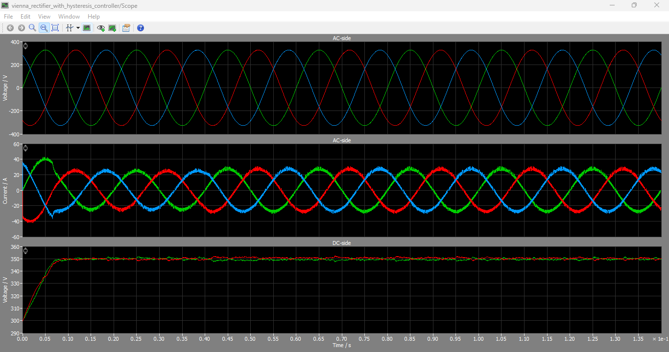
Figure 5: AC side Voltages, Currents and DC Voltages output graphs
You can download the Project files here: Download files now. (You must be logged in).
Figure 5 presents the simulation results showing the AC-side voltages, input currents, and DC-link output voltages of the Vienna Rectifier. The AC voltage waveforms demonstrate a balanced three-phase supply operating at the nominal grid frequency, while the corresponding input current waveforms exhibit nearly sinusoidal characteristics due to the action of the hysteresis current controller. The close phase alignment between the voltages and currents indicates near-unity power factor operation and effective power quality improvement. The lower portion of the waveform display shows the voltages across the two DC-link capacitors and the total DC output voltage. During startup, the capacitor voltages rise smoothly from their initial values and stabilize at approximately 350V each, resulting in a regulated total DC-link voltage of 700V. Following the introduction of an asymmetrical load disturbance, a temporary voltage imbalance appears between the capacitors; however, the center-point voltage controller rapidly compensates for the deviation and restores balanced operation within a short period. These results confirm the effectiveness of the proposed control strategy in achieving stable voltage regulation, balanced capacitor voltages, and high-quality input current waveforms.
Simulation results show that:
- Capacitor voltages rise smoothly toward 350V.
- Total DC-link voltage reaches 700V.
- No significant overshoot occurs.
- Input currents remain sinusoidal.
The startup process demonstrates the effectiveness of the cascaded control architecture in regulating the converter under initial charging conditions.
The hysteresis controller rapidly tracks the reference current, enabling fast capacitor charging without compromising current quality.
VII. Response Under Asymmetrical Loading
A key objective of the simulation is evaluating performance under unbalanced load conditions.
At approximately 0.4s, an asymmetrical load disturbance is introduced into the system.
Without neutral-point balancing control, one capacitor would charge more rapidly than the other, causing substantial voltage imbalance. Such behavior can increase semiconductor stress and reduce converter performance.
When the balancing controller is active, the following observations are obtained:
- Capacitor voltage deviation remains small.
- Neutral-point voltage remains stable.
- Voltage symmetry is restored rapidly.
- System stability is preserved.
Simulation results indicate that capacitor voltages return to balanced conditions within approximately 0.1s following the disturbance.
This fast recovery demonstrates the effectiveness of the implemented neutral-point voltage controller.
VIII. Input Current Quality and Power Factor Improvement
One of the most important characteristics of the Vienna Rectifier is its ability to draw nearly sinusoidal currents from the utility grid.
The current reference is generated by synchronizing with the measured mains voltages. Consequently, the converter input currents remain in phase with the source voltages.
The resulting benefits include:
- Near-unity power factor
- Reduced harmonic distortion
- Improved grid compatibility
- Enhanced energy efficiency
The hysteresis controller ensures accurate current tracking throughout the operating range.
Compared with uncontrolled diode rectifiers, the Vienna Rectifier significantly improves power quality while satisfying harmonic requirements imposed by modern power system standards.
IX. Advantages of the Proposed Control Strategy
The implemented cascaded control architecture provides several practical advantages.
- Improved Voltage Regulation
- The DC-link voltage controller maintains stable operation despite variations in load demand.
- Fast Dynamic Response
- Hysteresis current control offers immediate corrective action during transient events.
- Effective Neutral-Point Balancing
- The dedicated balancing controller successfully equalizes capacitor voltages under asymmetrical loading conditions.
- Reduced Harmonic Distortion
- Accurate current shaping minimizes harmonic injection into the utility grid.
- High Efficiency
- The three-level Vienna topology reduces semiconductor stress and switching losses.
- Robust Operation
- The controller maintains stability under startup conditions and load disturbances.
These characteristics make the proposed system suitable for high-power industrial applications.
X. Industrial Applications
The Vienna Rectifier has become a widely adopted solution in various industrial sectors that require high-performance AC-DC power conversion with improved efficiency, reduced harmonic distortion, and reliable operation. In telecommunications power supplies, Vienna Rectifiers are extensively used due to their ability to provide highly regulated DC output while maintaining low input current harmonics and high power factor, which are essential for ensuring continuous and reliable operation of communication infrastructure. Similarly, electric vehicle (EV) fast-charging stations utilize Vienna Rectifier technology because of its capability to deliver stable high-voltage DC power with excellent power quality characteristics and efficient energy conversion. In renewable energy systems, including energy storage units and grid-connected power interfaces, Vienna Rectifiers facilitate efficient power transfer while complying with grid harmonic standards. The aerospace and aviation industries also benefit from this topology because its three-level structure enables high efficiency, reduced component stress, and lightweight converter designs that are critical for aircraft power systems. Furthermore, in industrial automation applications such as motor drives, robotics, and process control systems, Vienna Rectifiers provide stable DC-link voltages and minimize harmonic pollution, thereby improving system performance and operational reliability. Owing to its superior efficiency, near-unity power factor operation, and effective voltage regulation capabilities, the hysteresis-controlled Vienna Rectifier presented in this study is well suited for deployment across these demanding industrial applications.
XI. Conclusion
This paper presented the modeling and simulation of a three-phase Vienna Rectifier employing hysteresis current control in the PLECS environment. The converter operates at 700V DC output and delivers approximately 12.25kW of power. A cascaded control structure comprising a DC-link voltage controller, a neutral-point voltage balancing controller, and a hysteresis current controller was implemented and evaluated.
Simulation results demonstrated successful startup operation, accurate DC voltage regulation, sinusoidal input current shaping, and effective neutral-point voltage balancing under asymmetrical loading conditions. The balancing controller restored capacitor voltage symmetry within approximately 0.1s following load disturbance, confirming its effectiveness.
The study verifies that hysteresis-controlled Vienna Rectifiers provide an efficient and robust solution for modern power conversion applications requiring high power quality, fast transient response, and reliable operation. Future work may investigate advanced control techniques such as predictive control, model predictive control, and space vector modulation methods to further enhance converter performance.
References
[1] J. W. Kolar and F. C. Zach, “A Novel Three-Phase Utility Interface Minimizing Line Current Harmonics of High-Power Telecommunications Rectifier Modules,” Proceedings of the 16th IEEE International Telecommunications Energy Conference (INTELEC), Vancouver, Canada, pp. 367–374, 1994.
[2] J. W. Kolar, U. Drofenik and F. C. Zach, “Space Vector Based Analysis of the Variation and Control of the Neutral Point Potential of Hysteresis Current Controlled Three-Phase/Three-Switch/Three-Level PWM Rectifier Systems,” International Conference on Power Electronics and Drive Systems (PEDS), Singapore, Vol. 1, pp. 22–33, 1995.
[3] N. Mohan, T. M. Undeland and W. P. Robbins, Power Electronics: Converters, Applications and Design, 3rd Edition, John Wiley & Sons, 2003.
[4] R. W. Erickson and D. Maksimovic, Fundamentals of Power Electronics, 2nd Edition, Springer, 2001.
You can download the Project files here: Download files now. (You must be logged in).







Responses