

Neutral-Point Clamped Three-Level Grid-Connected Converter with Decoupled dq Control: Modeling and Simulation in PLECS

Author: Waqas Javaid
Abstract
This paper presents the modeling, control, and simulation analysis of a three-level Neutral-Point Clamped (NPC) voltage source converter (VSC) designed for grid-connected applications. The system is developed using the PLECS simulation environment and operates as a bidirectional interface between a dynamic DC source and a 50 Hz AC grid. The converter employs a decoupled dq-axis current control strategy combined with an outer DC-link voltage regulation loop and a symmetrical three-level pulse width modulation (PWM) scheme with neutral-point voltage balancing. The study demonstrates the converter’s ability to regulate DC-link voltage at 450 V under varying input current conditions while maintaining high-quality sinusoidal grid currents. Simulation results validate improved harmonic performance, fast dynamic response, and effective power transfer capability compared to conventional two-level converters. The NPC topology ensures reduced switching stress and improved waveform quality, making it suitable for medium-to-high power renewable energy integration systems.
1. Introduction
The increasing penetration of renewable energy systems such as photovoltaic (PV) arrays and wind turbines has led to the widespread adoption of grid-connected power electronic converters. Among various topologies, the Neutral-Point Clamped (NPC) converter has emerged as a highly efficient solution for medium and high-power applications due to its superior harmonic performance and reduced device voltage stress compared to traditional two-level inverters [1].
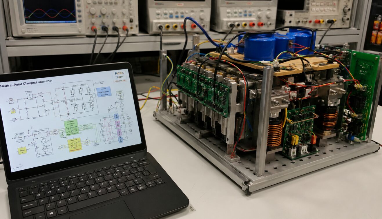
Figure 1: Experimental laboratory setup of a Neutral-Point Clamped (NPC) three-level converter system with real-time control and measurement interface.
The figure 1 illustrates a practical hardware implementation environment of a Neutral-Point Clamped (NPC) three-level converter system used for power electronics research and validation. On the left side, a laptop running a PLECS-based simulation interface displays the NPC converter schematic and control architecture, including modulation blocks, dq-axis current control, and DC-link regulation.
On the right side, the physical experimental prototype of the converter is visible, consisting of a modular power electronics assembly with insulated-gate bipolar transistor (IGBT) switching devices, gate driver circuits, copper windings, and energy storage components. The blue DC-link capacitors mounted on top provide energy buffering and voltage stabilization, while the integrated inductors and bus bars ensure controlled power transfer between DC and AC stages.
The setup is supported by laboratory-grade measurement instruments and power supplies in the background, enabling precise monitoring of voltage, current, and switching behavior under different operating conditions. This configuration closely represents real-world grid-connected converter systems used in renewable energy integration, such as photovoltaic inverters and smart grid interfaces.
Overall, the figure 1 demonstrates the transition from simulation-based design to hardware realization, validating the performance, control stability, and efficiency of the NPC converter under practical operating conditions.
The NPC converter, first introduced in multilevel converter research, enables the synthesis of a three-level output waveform using clamped diodes and split DC-link capacitors. This structure significantly reduces output voltage Total Harmonic Distortion (THD), improves efficiency, and distributes voltage stress across semiconductor devices more evenly [2].
This paper investigates a PLECS-based simulation model of a three-level NPC converter connected to a 50 Hz grid. The system includes a dynamic DC source representing photovoltaic input, a DC-link capacitor split, and a decoupled dq current control strategy with an outer voltage loop. A symmetrical PWM strategy ensures switching performance and neutral-point voltage balance.
2. System Description
2.1 Converter Topology
The studied system consists of a three-phase, three-level NPC voltage source converter. Each phase leg contains four active switches and clamping diodes that connect the midpoint of the DC bus to the output terminals. The DC-link is divided into two capacitors maintaining a balanced midpoint voltage.
The converter operates in both rectification and inversion modes, enabling bidirectional power flow between the DC source and AC grid. The grid is modeled as a balanced three-phase voltage source operating at 50 Hz with an RMS line voltage of 130 V [3].
The DC source is modeled as a controlled current source varying between 10 A and 15 A, representing dynamic solar irradiance conditions. This variation introduces transient disturbances in DC-link voltage, which are compensated by the control system.
2.2 DC-Link Structure
The DC-link consists of two capacitors (C₁ and C₂) connected in series. These capacitors maintain the total DC voltage (Vdc), while their midpoint serves as the neutral point. The initial capacitor voltage is set to 200 V, and the reference DC voltage is 450 V.
The energy stored in the DC-link is given by [4]:
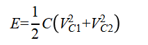
Where:
- E= total stored energy (Joules)
- C= capacitance of each DC-link capacitor (F)
- VC1, VC2= voltages across capacitors C1 and C2 (V)
This energy storage supports transient stability during sudden load or source variations [4].
3. Control Strategy
3.1 Outer DC Voltage Control Loop
The outer loop regulates the DC-link voltage at its reference value of 450 V using a PI controller. The error between measured voltage (Vdc) and reference voltage (Vdc*) generates the reference d-axis current (id*) [5].

Where:
- id* = reference d-axis current
- Vdc* = DC voltage reference (450 V)
- Vdc= measured DC voltage
- Kp, Ki= proportional and integral gains
This loop ensures power balance between AC and DC sides [5].
You can download the Project files here: Download files now. (You must be logged in).
3.2 Inner dq Current Control Loop
The inner loop controls active and reactive power flow by regulating d-axis (id) and q-axis (iq) currents. The dq transformation is synchronized using a Phase-Locked Loop (PLL) that extracts grid phase angle θ.
The current controllers are defined as:
- id controls active power
- iq controls reactive power
The controller outputs voltage references Vd* and Vq*, which are transformed back into abc frame for PWM generation.
3.3 Power Equations
The active and reactive power injected into the grid are calculated as [6]:
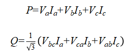
Where:
- P= active power (W)
- Q= reactive power (VAR)
- Va, Vb, Vc= phase voltages
- Ia, Ib, Ic= phase currents
- Vab, Vbc, Vca= line-to-line voltages
These equations describe instantaneous power transfer between converter and grid [6].
4. Modulation Technique
4.1 Symmetrical PWM for NPC Converter
The system uses a symmetrical three-level PWM scheme operating at 16 kHz switching frequency. The modulation indices (ma, mb, mc) are generated from voltage references and compared with carrier signals.
The three-level structure allows each phase to produce three voltage levels:
- +Vdc/2
- 0
- −Vdc/2
This reduces voltage stress across switching devices and improves waveform quality [7].
4.2 Neutral Point Voltage Balancing
A key challenge in NPC converters is maintaining equal voltage across DC-link capacitors. The model includes a balancing algorithm that adjusts switching states based on midpoint voltage deviation.
If capacitor voltages deviate, the modulation reference is shifted to restore balance.
5. Simulation Setup
The simulation is developed in PLECS 4.3.1 environment. The system consists of:
- Three-level NPC inverter
- Split DC-link capacitors
- Controlled current DC source (10 A → 15 A step change at 0.05 s)
- 50 Hz AC grid (130 VRMS)
- Decoupled dq control system
- PLL for synchronization
- Symmetrical PWM modulator (16 kHz)
Initial conditions are set with 200 V capacitor voltages, and the system stabilizes toward 450 V DC reference.
6. Results and Discussion
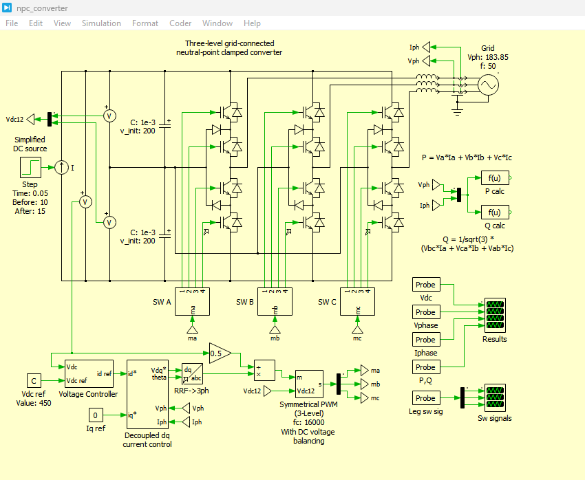
Figure 2: Three-level grid-connected neutral-point clamped converter model developed in PLECS
You can download the Project files here: Download files now. (You must be logged in).
Figure 2 illustrates the complete simulation architecture of the three-level Neutral-Point Clamped (NPC) converter implemented in the PLECS environment. The system consists of a DC-side power source, split DC-link capacitors, a three-phase NPC inverter, and a grid-connected AC interface. The DC source represents a renewable energy system, typically a photovoltaic array, whose output current varies dynamically to emulate real operating conditions.
The DC-link is divided into two capacitors, which establish a neutral point used by the NPC topology to generate three discrete voltage levels: +Vdc/2, 0, and −Vdc/2. This structure significantly improves output waveform quality and reduces harmonic distortion compared to conventional two-level converters.
On the AC side, the inverter is connected to a three-phase grid modeled as an ideal sinusoidal voltage source at 50 Hz. Each phase of the inverter is connected through an inductive filter, which smooths current ripple and ensures proper grid current injection.
The overall system is governed by a closed-loop control strategy consisting of an outer DC voltage controller and an inner dq-axis current controller. This enables bidirectional power flow, stable DC-link regulation, and controlled exchange of active and reactive power with the grid.
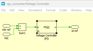
Figure 3: Voltage Controller circuit developed for NPC converter in PLECS
Figure 3 shows the outer-loop DC-link voltage control system implemented for regulating the converter’s DC bus voltage. The primary objective of this controller is to maintain the DC-link voltage at its reference value (450 V) despite variations in input power from the DC source.
A proportional-integral (PI) controller is used to compare the measured DC voltage (Vdc) with the reference voltage (Vdc*). The resulting error is processed to generate the reference d-axis current (id*), which defines the required active power exchange with the grid.
The controller ensures that any imbalance between input power (from the DC source) and output power (to the grid) is corrected by adjusting the grid current demand. When the DC source current increases (e.g., from 10 A to 15 A), the controller reacts by increasing the power injected into the grid, thereby stabilizing the DC-link voltage.
This control loop is essential for maintaining energy balance and ensuring stable converter operation under dynamic conditions.
6.1 DC-Link Voltage Response
Simulation results show that DC voltage initially deviates due to step change in input current. However, the PI controller restores voltage to 450 V within approximately 50 ms, demonstrating fast dynamic response.
This confirms the effectiveness of outer-loop voltage regulation in maintaining power balance.
6.2 Grid Current Performance
The dq current controller ensures sinusoidal grid currents with minimal harmonic distortion. The PLL maintains synchronization with the grid voltage, ensuring stable operation under varying load conditions.
The current waveforms show proper phase alignment with grid voltages, indicating unity power factor operation when iq reference is set to zero.
6.3 Power Flow Analysis
Active power increases when DC source current increases from 10 A to 15 A, while reactive power remains controlled. This demonstrates independent control of P and Q using dq decoupling strategy.
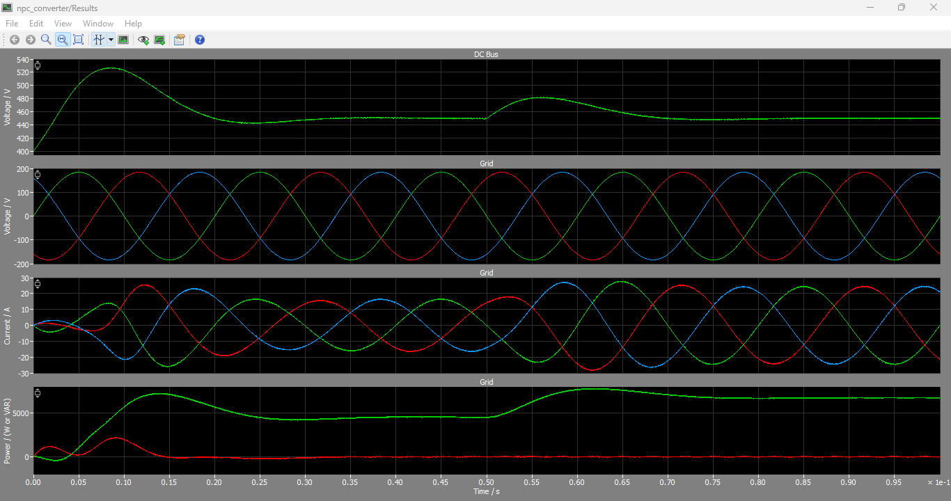
Figure 4: Output DC Bus Voltage, Grid three phase Voltages, Grid three phase Currents and Grid Power output graphs
You can download the Project files here: Download files now. (You must be logged in).
Figure 4 presents the key electrical performance waveforms of the NPC converter system, including DC-link voltage, grid voltages, grid currents, and power flow characteristics.
The DC bus voltage waveform demonstrates effective regulation around the reference value of 450 V. A transient deviation is observed during the step change in DC source current; however, the control system rapidly restores stability within approximately 50 ms.
The grid voltage waveforms remain sinusoidal and stable, as they are dictated by the ideal grid model. More importantly, the grid current waveforms closely follow sinusoidal shapes and are phase-aligned with grid voltages, indicating near-unity power factor operation.
The active and reactive power profiles confirm that the system successfully transfers power from the DC source to the AC grid. Active power increases in response to higher DC input current, while reactive power remains controlled near zero due to dq-axis decoupling.
These results validate the effectiveness of the control strategy in ensuring high-quality power injection and stable converter operation under dynamic conditions.
6.4 Switching Behavior
The PWM output shows a distinct three-level switching pattern. Compared to two-level converters, switching stress is reduced, leading to improved efficiency and reduced electromagnetic interference (EMI).
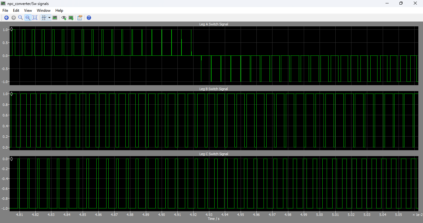
Figure 5: Gate switching signals of Leg A, B and C
Figure 5 presents the gate driver signals generated for the three inverter legs (A, B, and C) of the NPC converter. These signals are produced by the symmetrical three-level PWM modulator operating at a switching frequency of 16 kHz.
Each phase leg contains multiple switching states that allow the output voltage to switch among three levels: positive half DC voltage, zero voltage, and negative half DC voltage. The gating signals ensure proper coordination of upper and lower switches to avoid short circuits and maintain safe commutation.
Additionally, the modulation strategy incorporates a neutral-point balancing mechanism. This ensures equal voltage distribution across the split DC-link capacitors by dynamically adjusting switching patterns based on capacitor voltage deviation.
The resulting gate signals exhibit phase displacement of 120°, consistent with a balanced three-phase system. This confirms correct PWM operation and proper synchronization with the grid reference angle generated by the Phase-Locked Loop (PLL).
6.5 Neutral Point Stability
The capacitor voltage balancing algorithm effectively maintains midpoint stability. Without this control, voltage imbalance could lead to device stress and waveform distortion [8].
7. Advantages of NPC Converter
The NPC topology provides several advantages:
- Reduced harmonic distortion
- Lower device voltage stress
- Improved efficiency in high power systems
- Better output waveform quality
- Suitable for renewable energy integration
These advantages make it a preferred choice in PV inverters and grid-tied applications [9].
8. Conclusion
This paper presented a comprehensive modeling and simulation study of a three-level Neutral-Point Clamped converter using PLECS. The system integrates a decoupled dq control strategy, outer DC voltage regulation, and symmetrical PWM with neutral-point balancing.
Simulation results confirm that the converter effectively regulates DC-link voltage at 450 V under dynamic input conditions and maintains high-quality sinusoidal grid currents. The NPC topology significantly improves harmonic performance and reduces switching stress compared to conventional two-level converters.
The study validates the suitability of NPC converters for renewable energy systems, smart grids, and high-power industrial applications. Future work may include hardware implementation and comparison with other multilevel converter topologies such as cascaded H-bridge and flying capacitor converters.
References
[1] J. Rodriguez, J. Lai, and F. Peng, “Multilevel inverters: A survey of topologies, controls, and applications,” IEEE Transactions on Industrial Electronics, vol. 49, no. 4, pp. 724–738, 2002.
[2] A. Nabae, I. Takahashi, and H. Akagi, “A new neutral-point-clamped PWM inverter,” IEEE Transactions on Industry Applications, vol. IA-17, no. 5, pp. 518–523, 1981.
[3] PLECS GmbH, “Neutral-Point Clamped Converter Demo Model,” PLECS Documentation 4.3.1, 2023.
[4] N. Mohan, T. Undeland, and W. Robbins, Power Electronics: Converters, Applications, and Design, Wiley, 2003.
[5] R. Teodorescu, M. Liserre, and P. Rodriguez, Grid Converters for Photovoltaic and Wind Power Systems, Wiley, 2011.
[6] S. Buso and P. Mattavelli, Digital Control in Power Electronics, Morgan & Claypool, 2006.
[7] J. Holtz, “Pulsewidth modulation for electronic power conversion,” Proceedings of the IEEE, vol. 82, no. 8, pp. 1194–1214, 1994.
[8] H. Abu-Rub, J. Holtz, J. Rodriguez, and G. Baoming, “Medium-voltage multilevel converters—state of the art and new developments,” IEEE Transactions on Industrial Electronics, vol. 57, no. 7, 2010.
[9] B. Wu, High-Power Converters and AC Drives, Wiley-IEEE Press, 2006.
You can download the Project files here: Download files now. (You must be logged in).







Responses