

Advanced Three-Level Grid-Connected Neutral Point Clamped Solar Inverter with LCL Filter and Active Damping for Real-Time Hardware-in-the-Loop Applications
Author: Waqas Javaid
Abstract
This paper presents the modeling, control, simulation, and real-time implementation of a three-level Neutral Point Clamped (NPC) grid-connected solar inverter integrated with an LCL filter and active damping technique. The proposed inverter system is designed for medium-voltage photovoltaic (PV) applications requiring improved power quality, reduced harmonic distortion, and stable grid synchronization. A Space Vector Pulse Width Modulation (SVPWM) strategy is implemented for switching control of the three-level NPC topology. In addition, a neutral-point balancing algorithm is introduced to maintain equal voltages across the split DC-link capacitors. The resonance introduced by the LCL filter is mitigated using an active damping approach based on capacitor current feedback, thereby eliminating additional passive damping losses. The complete system is modeled in PLECS and implemented using RT Box hardware for real-time Hardware-in-the-Loop (HIL) validation. The controller and plant models are separated into independent subsystems for computational efficiency and rapid prototyping. Simulation and real-time experimental results demonstrate stable operation under DC voltage disturbances and current reference variations while maintaining low harmonic distortion and unity power factor. The proposed architecture achieves efficient grid integration for high-power photovoltaic applications and validates the suitability of real-time simulation platforms for advanced converter research.
I. Introduction
Renewable energy systems have become increasingly important due to the growing demand for clean and sustainable electrical power generation. Among renewable technologies, photovoltaic (PV) systems have gained significant popularity because of their modularity, reliability, and decreasing installation cost. However, efficient integration of photovoltaic systems into the electrical grid requires advanced power electronic converters capable of maintaining power quality and system stability [1].
Two-level voltage source inverters have traditionally been employed in grid-connected photovoltaic systems. Nevertheless, as power ratings increase, conventional two-level inverters suffer from high switching losses, elevated harmonic distortion, and large voltage stress on semiconductor devices. Multilevel inverter topologies provide an effective solution to these limitations by generating output voltages with multiple discrete levels, thereby improving waveform quality and reducing filter requirements [2].
Among multilevel topologies, the Neutral Point Clamped (NPC) inverter has emerged as one of the most widely adopted structures for medium- and high-power applications due to its simple architecture and reduced switching stress [3]. The three-level NPC inverter produces output voltages with three distinct levels: positive, zero, and negative DC-link potentials. This significantly reduces Total Harmonic Distortion (THD) while improving conversion efficiency.
To further enhance harmonic attenuation, LCL filters are commonly employed between the inverter and the utility grid. Compared to simple inductive filters, LCL filters provide superior attenuation of switching harmonics with smaller inductance values [4]. However, the resonance introduced by the LCL network may destabilize the current control loop if proper damping techniques are not implemented.
Traditionally, passive damping resistors are inserted into the filter structure to suppress resonant oscillations. Although effective, passive damping introduces additional power losses and reduces system efficiency. Consequently, active damping strategies have gained attention due to their capability of emulating damping behavior without introducing physical resistive losses [5].
In this work, a capacitor-current-feedback-based active damping method is implemented in conjunction with a three-level NPC inverter operating under Space Vector Pulse Width Modulation (SVPWM). Furthermore, a neutral-point voltage balancing algorithm is employed to maintain equal voltage sharing across the split DC capacitors. The complete converter system is implemented in PLECS and validated through real-time simulation using RT Box platforms.
The major contributions of this paper are summarized as follows:
- Development of a detailed three-level NPC inverter model for grid-connected photovoltaic applications.
- Design and analysis of an LCL filter for harmonic suppression.
- Implementation of active damping using capacitor current feedback.
- Development of a simplified three-level SVPWM strategy.
- Real-time Hardware-in-the-Loop implementation using RT Box.
- Validation of neutral-point voltage balancing during transient conditions.
II. System Configuration and Modeling
A. Overall System Architecture
The proposed grid-connected photovoltaic system consists of:
- Photovoltaic DC source
- Split DC-link capacitors
- Three-level NPC inverter
- LCL filter
- Grid interface
- dq-axis current controller
- SVPWM modulation block
- Active damping controller
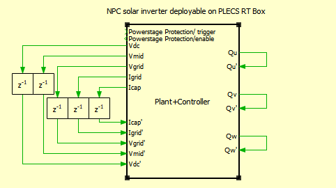
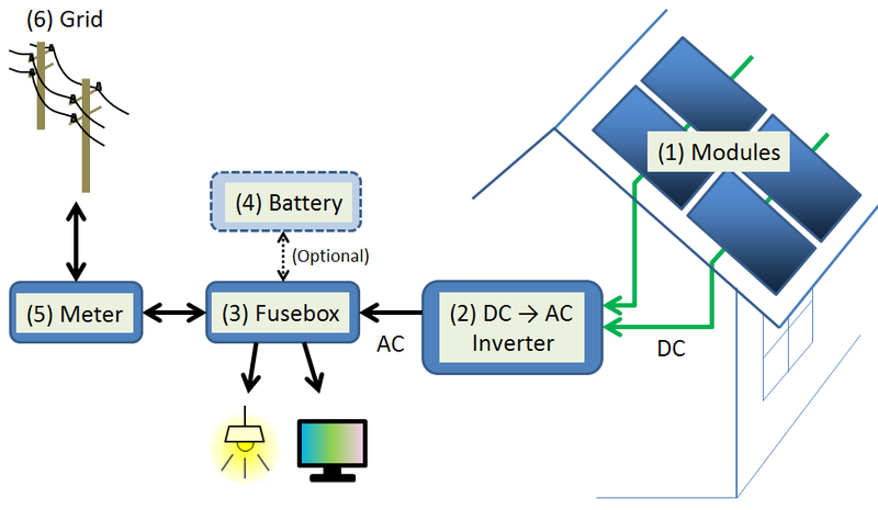
Figure 1: Overall architecture of the grid-connected three-level NPC inverter system.
Figure 1 illustrates the complete system architecture including the photovoltaic source, DC-link capacitors, NPC inverter, LCL filter, and grid connection. The controller subsystem generates PWM gating signals based on measured grid currents and voltages.
B. Photovoltaic Source Model
The photovoltaic source is represented by an equivalent DC voltage source whose magnitude depends on solar irradiation conditions. The DC-link voltage is maintained around 800 V under nominal conditions.
The generated PV voltage is represented as:
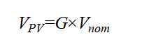
where:
- V_PV = photovoltaic output voltage (V)
- G = normalized solar irradiation factor
- V_nom= nominal DC-link voltage (800 V)
Equation (1) models the dependency of PV voltage on solar intensity [1].
C. Split DC-Link Capacitors
Two DC capacitors are connected in series to create the neutral point required by the NPC topology.
The total DC-link voltage is:
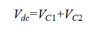
where:
- V_dc= total DC-link voltage
- V_C1= upper capacitor voltage
- V_C2= lower capacitor voltage
Ideally:
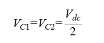
The balancing of capacitor voltages is essential for stable inverter operation [4].
III. Three-Level NPC Inverter
A. Operating Principle
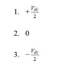
The three-level NPC inverter consists of four switches per phase leg and two clamping diodes. The inverter produces three output voltage levels:
B. Switching States
The switching combinations are summarized as follows:
Table 1: Switching states and corresponding output voltage levels of the three-level NPC inverter.
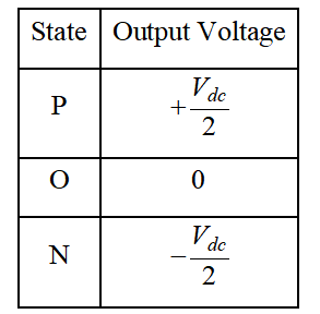
Table 1 summarizes the fundamental switching states of the three-level Neutral Point Clamped (NPC) inverter and their corresponding output voltage levels. The three operating states, namely Positive (P), Zero (O), and Negative (N), are generated by different combinations of the inverter power switches within each phase leg. In the positive state (P), the inverter output terminal is connected to the positive DC-link rail, producing an output voltage of +Vdc/2. In the zero state (O), the output terminal is connected to the neutral point of the split DC capacitors, resulting in zero output voltage. Similarly, in the negative state (N), the output terminal is connected to the negative DC-link rail, generating an output voltage of −Vdc/2. These three discrete voltage levels enable the inverter to synthesize output waveforms with lower harmonic distortion and reduced voltage stress compared to conventional two-level inverters. The multilevel switching capability significantly improves waveform quality, reduces switching losses, and enhances the overall efficiency of the grid-connected photovoltaic inverter system. The inverter output voltage vector is synthesized using SVPWM techniques [3].
IV. LCL Filter Design
A. Need for LCL Filter
The inverter switching operation generates high-frequency harmonics. An LCL filter is inserted between the inverter and grid to attenuate these harmonics.
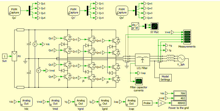
Figure 2: Schematic of the grid-connected three-level NPC inverter with LCL-filter and active damping
You can download the Project files here: Download files now. (You must be logged in).
Figure 2 presents the PLECS simulation schematic of a grid-connected three-level Neutral Point Clamped (NPC) inverter integrated with an LCL filter and active damping control. The model includes a photovoltaic DC source, split DC-link capacitors, three-phase NPC inverter legs, grid-side filter components, and measurement blocks for voltage and current sensing. The controller subsystem generates SVPWM-based switching pulses to regulate inverter output currents and maintain stable grid synchronization. In addition, the active damping mechanism utilizes filter capacitor current feedback to suppress LCL resonance and improve system stability during real-time operation.
B. Base Quantities
The base impedance is defined as [1]:
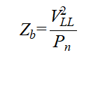
where:
- Zb= base impedance
- VLL= line-to-line RMS voltage
- Pn= rated active power
The base capacitance is:
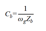
where:
- Cb= base capacitance
- ωg = 2Πfg
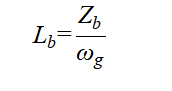
The base inductance is:
C. Filter Capacitor Design
The filter capacitor is selected as:
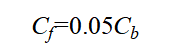
This ensures reactive power variation remains within acceptable limits [1].
D. Filter Inductor Design
The total filter inductance is:
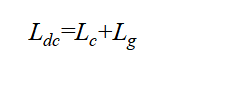
where:
- Lc= converter-side inductance
- Lg= grid-side inductance
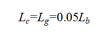
Assuming equal distribution:
E. Resonant Frequency
The resonant frequency of the LCL filter is given by [1]:
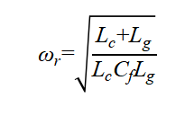
where:
- ωr= resonant frequency
- Lc= converter-side inductance
- Lg= grid-side inductance
- Cf= filter capacitance
V. Active Damping Technique
A. Need for Active Damping
The resonance introduced by the LCL filter can destabilize the control system. Passive damping introduces power losses; therefore, active damping is preferred.
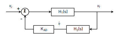
Figure 3: Block diagram representation of active damping using capacitor current feedback.
Figure 3 presents the active damping control loop where capacitor current feedback emulates a virtual damping resistor without physical power dissipation.
B. Damping Resistor
The equivalent damping resistor is selected as [2]:
where:
- R_D= damping resistance
- ωr= resonant frequency
- Cf= filter capacitance
C. Virtual Damping Gain
The active damping gain is:
where:
- K_AD= active damping gain
- Lc= converter-side inductance
- Lg= grid-side inductance
- R_D= virtual damping resistance
This virtual resistor effectively suppresses resonant oscillations [5].
VI. Space Vector Pulse Width Modulation
A. Principle of SVPWM
SVPWM generates optimized switching signals by synthesizing reference voltage vectors using adjacent active vectors and zero vectors.
B. Reference Vector Synthesis
The synthesized voltage vector satisfies:
where:
- V_X, V_Y, V_Z= selected space vectors
- T_X, T_Y, T_Z= dwelling times
- Vref= reference voltage vector
- Tsw= switching period
The dwelling times satisfy:
![]()
VII. Neutral-Point Voltage Balancing
A. Problem Statement
Unequal capacitor voltages cause neutral-point drift, resulting in distorted output voltages and increased stress on semiconductor devices.
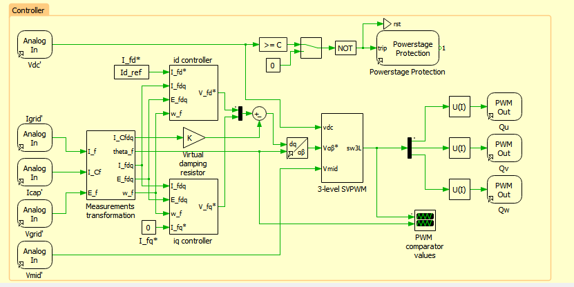
Figure 4: Control scheme of the grid-connected three-level NPC inverter using SVPWM method
Figure 4 presents the control architecture of the grid-connected three-level NPC inverter based on the Space Vector Pulse Width Modulation (SVPWM) technique. The control system includes dq-axis current controllers, reference frame transformations, active damping loops, and neutral-point voltage balancing mechanisms for stable inverter operation. Measured grid currents, capacitor currents, and DC-link voltages are processed to generate accurate switching pulses for the NPC inverter. The proposed control strategy ensures low harmonic distortion, balanced DC capacitor voltages, and synchronized power injection into the utility grid.
B. Neutral-Point Current
The neutral-point current depends on switching states and phase currents:
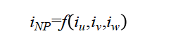
where:
- i_NP= neutral-point current
- iu, iv, iw= phase currents
The controller manipulates zero-vector dwelling times to maintain capacitor voltage balance [4].
VIII. dq-Axis Current Control
A. Current Controller Design
The inverter current is regulated using synchronous reference frame PID controllers.
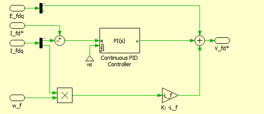
Figure 5: dq-axis current control structure for the grid-connected inverter.
You can download the Project files here: Download files now. (You must be logged in).
Figure 5 shows the current regulation loops for d-axis and q-axis currents including PID controllers and decoupling terms.
B. Plant Transfer Function
The system transfer function is approximated as [1]:
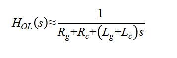
where:
- Rg= grid resistance
- Rc= converter resistance
- Lg= grid inductance
- Lc= converter inductance
IX. Real-Time Hardware-in-the-Loop Implementation
A. RT Box Architecture
The plant and controller subsystems are implemented on separate RT Boxes for computational efficiency.
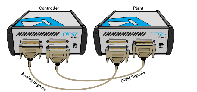
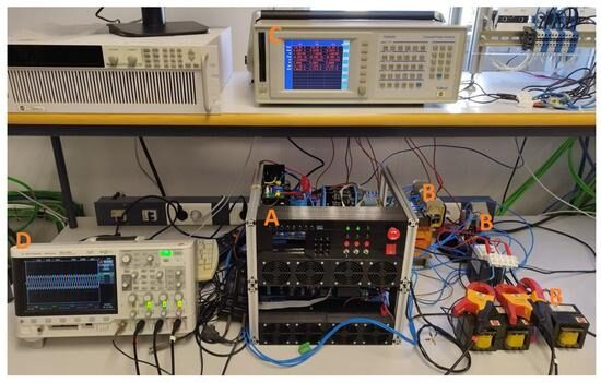
Figure 6: Hardware-in-the-Loop setup using dual RT Boxes.
Figure 6 presents the real-time implementation where one RT Box executes the plant model while another RT Box executes the controller subsystem.
B. Execution Timing
The controller subsystem operates with a discretization step of 50 µs, while the plant subsystem operates with a step size of 7 µs.
This separation significantly reduces computational burden and improves real-time execution performance.
X. Simulation and Experimental Results
The proposed three-level grid-connected Neutral Point Clamped (NPC) inverter system with LCL filter and active damping was modeled and analyzed in the PLECS simulation environment. The developed model includes the photovoltaic DC source, split DC-link capacitors, three-level inverter topology, dq-axis current control loops, active damping mechanism, and Space Vector Pulse Width Modulation (SVPWM) switching strategy. The simulation was performed to evaluate the dynamic performance, harmonic suppression capability, current tracking response, switching behavior, and grid synchronization characteristics of the proposed converter system under different operating conditions.
The inverter was designed to transfer power from an 800 V DC photovoltaic source to a three-phase 230 Vrms, 50 Hz utility grid through an LCL filter. The controller subsystem continuously monitored the grid voltages, grid currents, capacitor currents, and DC-link voltages to generate accurate switching pulses for the inverter power switches. The active damping loop effectively minimized resonance oscillations introduced by the LCL filter, while the neutral-point balancing algorithm maintained equal voltage distribution across the split DC-link capacitors. The simulation results confirmed stable system operation with reduced harmonic distortion and smooth current injection into the utility grid.
The dynamic response of the system was further analyzed under DC-link voltage disturbances and current reference variations. During transient operating conditions, the dq-axis PI controllers successfully regulated the inverter currents and maintained synchronization with the utility grid. The inverter output currents remained sinusoidal with minimal oscillations, demonstrating the effectiveness of the SVPWM strategy and active damping technique. Moreover, the controller maintained unity power factor operation by regulating the q-axis current reference near zero. The overall results verified that the proposed converter topology is suitable for high-performance photovoltaic grid integration applications.
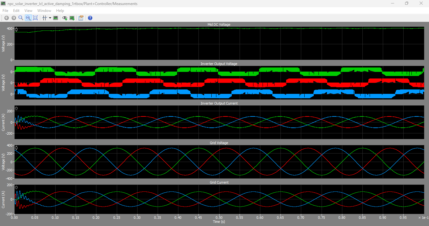
Figure 7: Md DC Voltage, Inverter output voltages, Inverter Output Current, Grid Voltage and Grid current graphs generated by PLECS Simulation model
Figure 7 presents the major electrical waveforms obtained from the developed PLECS simulation model of the grid-connected three-level NPC inverter. The figure includes the DC-link voltage waveform, inverter output voltages, inverter output currents, grid voltages, and grid currents under steady-state operating conditions. The DC-link voltage waveform demonstrates stable voltage regulation around the desired operating value, confirming that the split capacitor balancing algorithm effectively maintains equal voltage sharing across the upper and lower DC capacitors.
The inverter output voltage waveforms clearly exhibit the multilevel characteristics of the three-level NPC inverter topology. Compared with conventional two-level inverters, the generated voltage waveform contains smaller voltage steps and reduced switching stress, which significantly improves power quality and lowers harmonic distortion. The SVPWM technique generates balanced three-phase output voltages with accurate modulation indices and proper switching sequences.
The inverter output current waveforms shown in Figure 7 are smooth and sinusoidal due to the harmonic filtering capability of the LCL filter and the active damping controller. The grid current waveforms closely follow the grid voltage waveforms, demonstrating proper synchronization and unity power factor operation. The phase alignment between grid voltage and grid current confirms that the proposed control strategy effectively regulates active power transfer while minimizing reactive power injection into the utility grid.
Additionally, the active damping mechanism successfully suppresses oscillations caused by the LCL filter resonance. The absence of excessive ringing or instability in the current waveforms validates the effectiveness of the capacitor-current-feedback-based active damping approach. Overall, the results presented in Figure 7 verify the stable operation, harmonic reduction capability, and efficient grid integration performance of the proposed inverter system.
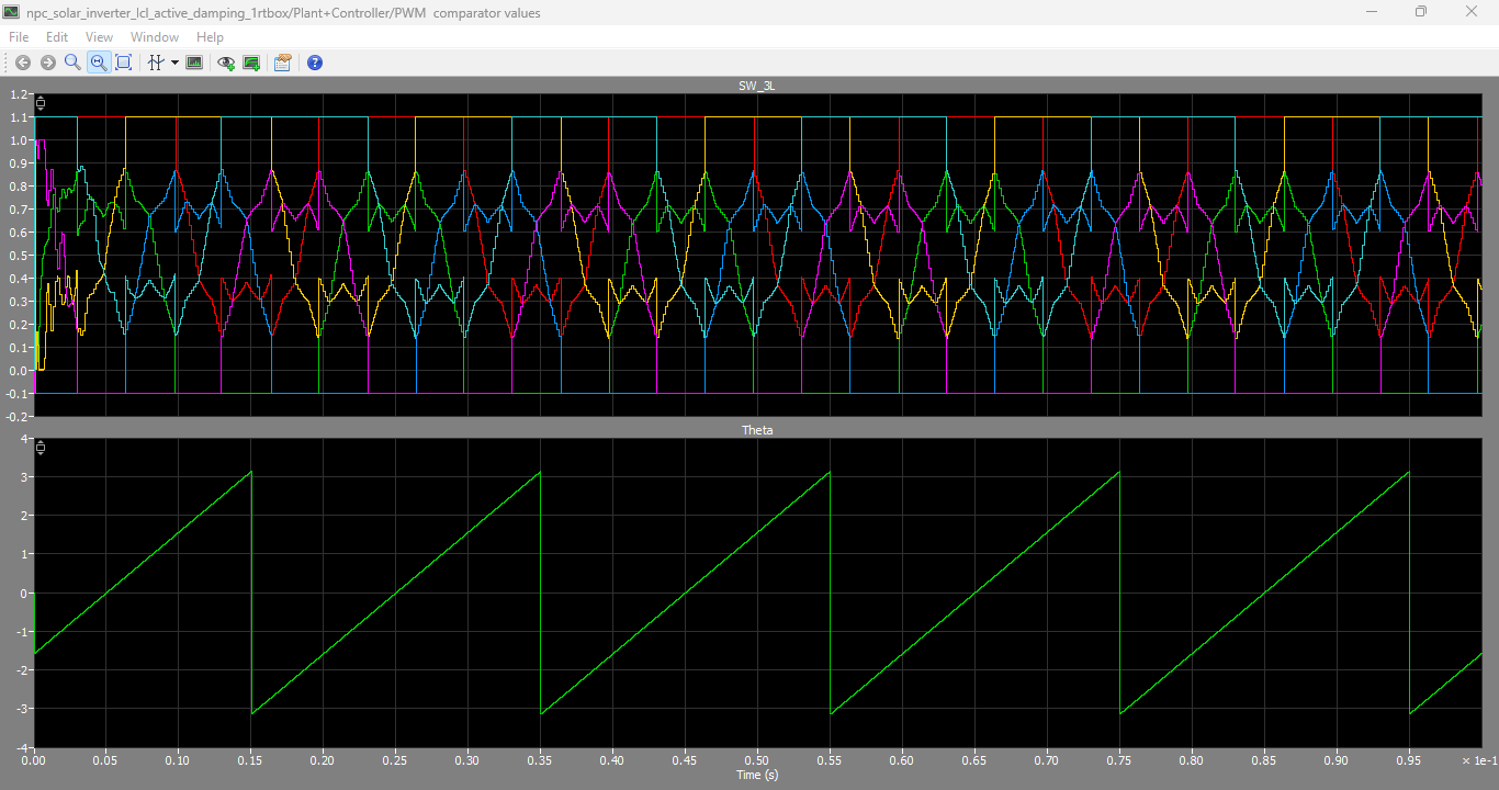
Figure 8: Switching logic output graphs and theta output graph
You can download the Project files here: Download files now. (You must be logged in).
Figure 8 illustrates the switching logic signals generated by the SVPWM controller together with the theta output waveform used for synchronous reference frame transformation and grid synchronization. The switching logic waveforms represent the gate pulses applied to the inverter switches of the three-level NPC topology. These pulses are generated according to the SVPWM algorithm, which determines the appropriate switching states and dwelling times of the space vectors in each switching cycle.
The switching pulses exhibit symmetrical and properly sequenced patterns, ensuring balanced operation of all inverter legs. The SVPWM strategy distributes switching states efficiently among the semiconductor devices, thereby reducing switching losses and improving voltage utilization. Furthermore, the switching logic maintains proper complementary operation between upper and lower switches in each phase leg to avoid short-circuit conditions across the DC-link capacitors.
The theta output waveform shown in Figure 8 represents the angular position of the rotating synchronous reference frame used in dq-axis transformations. This angle is typically generated through a Phase Locked Loop (PLL) mechanism synchronized with the utility grid voltage. The smooth and continuous variation of the theta waveform confirms accurate grid synchronization and stable phase tracking during inverter operation.
Accurate theta generation is critical for dq-axis current control because it enables precise transformation of three-phase AC quantities into rotating reference frame components. This allows independent regulation of active and reactive current components, thereby improving dynamic response and control accuracy. The results shown in Figure 8 confirm that the proposed control architecture provides reliable switching signal generation and stable synchronization for grid-connected operation of the three-level NPC inverter system.
XI. Discussion
The simulation and real-time results demonstrate that the proposed three-level NPC inverter achieves excellent grid integration performance. The active damping approach successfully suppresses resonance without introducing power losses associated with passive damping resistors. Additionally, the neutral-point balancing algorithm effectively maintains equal capacitor voltages even during transient disturbances.
Compared with conventional two-level converters, the proposed topology exhibits lower harmonic distortion, reduced switching stress, and improved waveform quality. The implementation using RT Box hardware further validates the suitability of the proposed method for real-time Hardware-in-the-Loop applications and rapid control prototyping.
XII. Conclusion
This paper presented the design, implementation, and real-time validation of a three-level grid-connected NPC inverter with LCL filter and active damping. The proposed system integrates advanced SVPWM control, neutral-point voltage balancing, and capacitor-current-based active damping to achieve stable and efficient grid-connected operation.
The developed control architecture was implemented using PLECS and RT Box platforms for Hardware-in-the-Loop validation. Simulation and experimental results verified the effectiveness of the proposed methods under varying operating conditions. The proposed inverter system provides a promising solution for high-power photovoltaic grid integration applications.
Future work may include fault-tolerant operation, adaptive control techniques, model predictive current control, and integration with energy storage systems.
References
[1] R. Teodorescu, M. Liserre, and P. Rodriguez, Grid Converters for Photovoltaic and Wind Power Systems. Hoboken, NJ, USA: Wiley-IEEE Press, 2011.
[2] R. W. Erickson, “Optimal single resistors damping of input filters,” in Proc. IEEE Applied Power Electronics Conference (APEC), 1999, pp. 1073–1079.
[3] V. Xue, “Center-Aligned SVPWM Realization for 3-Phase 3-Level Inverter,” Texas Instruments Application Report, Oct. 2012.
[4] N. Celanovic and D. Boroyevich, “A comprehensive study of neutral-point voltage balancing problem in three-level neutral-point-clamped voltage source PWM inverters,” IEEE Transactions on Power Electronics, vol. 15, no. 2, pp. 242–249, Mar. 2000.
[5] J. Dannehl, F. W. Fuchs, and S. Hansen, “Investigation of active damping approaches for PI-based current control of grid-connected pulse width modulation converters with LCL filters,” IEEE Transactions on Industry Applications, vol. 46, no. 4, pp. 1509–1517, Jul. 2010.
[6] H. Abu-Rub, M. Malinowski, and K. Al-Haddad, Power Electronics for Renewable Energy Systems, Transportation and Industrial Applications. Hoboken, NJ, USA: Wiley, 2014.
[7] B. Wu, High-Power Converters and AC Drives. Hoboken, NJ, USA: Wiley-IEEE Press, 2006.
[8] J. Rodriguez, J. Lai, and F. Peng, “Multilevel inverters: A survey of topologies, controls, and applications,” IEEE Transactions on Industrial Electronics, vol. 49, no. 4, pp. 724–738, Aug. 2002.
[9] D. G. Holmes and T. A. Lipo, Pulse Width Modulation for Power Converters: Principles and Practice. Hoboken, NJ, USA: Wiley-IEEE Press, 2003.
[10] Plexim GmbH, “Three-Level Grid-Connected NPC Solar Inverter with LCL-Filter and Active Damping,” RT Box Demo Documentation, Zurich, Switzerland, 2023.
You can download the Project files here: Download files now. (You must be logged in).


Responses