

Sensorless Vector Control for Permanent Magnet Synchronous Machine Development in PLECS
Author: Waqas Javaid
Abstract
This paper presents a sensorless vector control strategy for a Permanent Magnet Synchronous Machine (PMSM) using an observer-based position and speed estimation technique. The drive system consists of a 24V DC-fed three-phase voltage source inverter driving a 40W PMSM with nominal torque of 0.11 Nm. A cascaded control structure is implemented with inner dq-axis current controllers and an outer speed controller. Rotor position and speed are estimated using a reduced-order observer based on extended electromotive force (EMF) in the γδ reference frame, eliminating the need for physical encoders. The control algorithm is validated through both offline simulation and real-time implementation on the PLECS RT Box platform. Experimental results demonstrate robust speed tracking and load disturbance rejection, with transient response times of approximately 0.5 seconds for speed recovery under load steps. The observer achieves accurate position estimation with minimal error during step changes from 1000 rpm to 2000 rpm.
I. Introduction
Permanent magnet synchronous machines (PMSMs) are widely used in modern drive applications due to their high efficiency, high power density, and excellent dynamic performance. Traditional field-oriented control (FOC) of PMSMs requires rotor position information, typically obtained from encoders or resolvers. However, these mechanical sensors increase system cost, reduce reliability, and require additional maintenance [1].
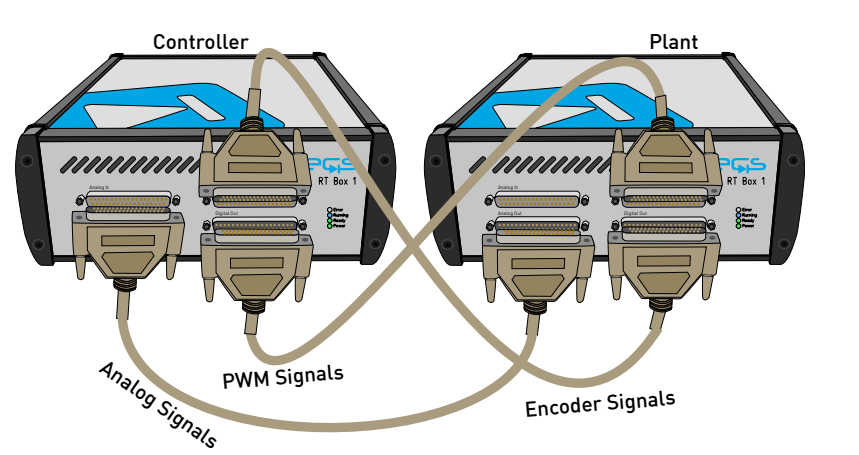
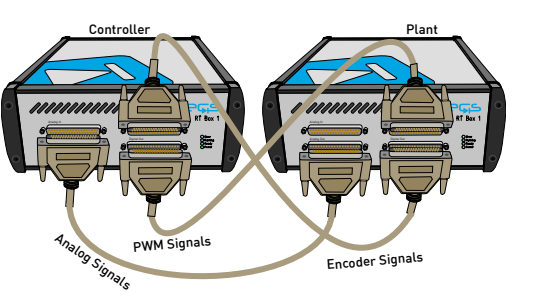
Figure 1: Hardware configuration for the real-time operation of the demo model
You can download the Project files here: Download files now. (You must be logged in).
Figure 1 illustrates the hardware configuration for real-time operation of the demo model using two PLECS RT Boxes connected via three 37-pin Sub-D cables. One RT Box is designated as the “Plant,” running the PMSM, inverter, and power stage model, while the second RT Box serves as the “Controller,” executing the sensorless FOC algorithm and observer. The front-to-front connection enables bidirectional signal exchange: analog outputs from the Plant connect to analog inputs on the Controller, and digital outputs interface with digital inputs. For users with only one RT Box, multi-tasking is enabled where the Controller runs as a Task frame on one core and the Plant runs as the Base task on another core. This separation minimizes execution time per target and allows seamless transition to hardware-in-the-loop (HIL) or rapid control prototyping (RCP) testing. Sensorless control techniques have emerged as an attractive alternative to eliminate position sensors. These methods estimate rotor position and speed from measured electrical quantities such as stator currents and voltages. Among various sensorless approaches, observer-based methods using extended electromotive force (EMF) have shown particular promise for medium to high-speed operation [1].
This paper presents a complete sensorless vector control system for a PMSM drive, implemented on the PLECS RT Box platform.
The system features:
- a cascaded speed-current control structure,
- a reduced-order observer for position and speed estimation,
- offline simulation and real-time hardware-in-the-loop (HIL) capabilities,
- dual RT Box configuration for plant and controller separation.
II. System Modeling
A. Machine Model
The PMSM used in this study is model BLWS232D-36V-4000 with the specifications listed in Table I. The machine has 2 pole pairs, rated power of 40 W, rated torque of 0.1 Nm, and rated speed of 4000 rpm. The line-to-line resistance is 2.4 Ω, and the line-to-line inductance is 4.39 mH. The rotor inertia is 7.4852 × 10⁻⁶ Nms², and the back EMF is 4.5 V/krpm.
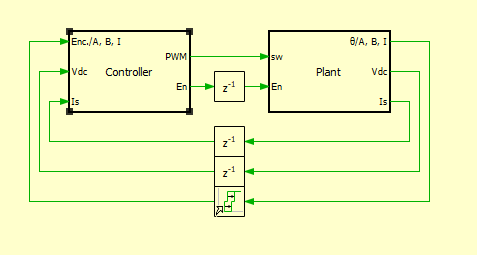
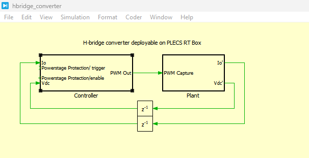
Figure 2: Top level schematic of the demo model sensorless speed controlled PMSM
Figure 2 presents the top-level schematic is split into two main subsystems: Plant (containing the PMSM, inverter, and power stage) and Controller (containing the control logic, observer, and PWM generation). This separation allows the same model to run in offline simulation on a computer or in real-time on one or two RT Boxes, with Delay blocks (z^-1) modeling the inherent closed-loop control delays.
Table 1: Specifications of Applied PMSM BLWS232D-36V-4000
| Parameter | Value |
| Number of pole pairs | 2 |
| Rated Power (W) | 40 |
| Rated Torque (Nm) | 0.1 |
| Rated Speed (rpm) | 4000 |
| Line to Line Resistance (Ω) | 2.4 |
| Line to Line Inductance (mH) | 4.39 |
| Rotor Inertia (Nms²) | 0.0000074852 |
| Back EMF Voltage (V/krpm) | 4.5 |
Table 1 presents the key electrical and mechanical specifications of the BLWS232D-36V-4000 permanent magnet synchronous machine (PMSM) used in the drive system. These parameters include the number of pole pairs, rated power (40 W), rated torque (0.1 Nm), rated speed (4000 rpm), line-to-line resistance (2.4 Ω), line-to-line inductance (4.39 mH), rotor inertia, and back EMF voltage (4.5 V/krpm).
For modeling purposes, line-to-line quantities must be converted to line-to-neutral quantities by dividing by √3. The permanent magnet flux linkage ψ is calculated from the back EMF voltage using [2]:

where p is the number of pole pairs, ψ is the flux linkage, and ω is the angular speed in rad/s.
B. The PMSM Drive Plant Subsystem
The plant subsystem comprises a permanent magnet synchronous machine (PMSM) driven by a three-phase voltage source inverter (VSI). The power stage is supplied by a 24 V DC voltage source and features three MOSFET half-bridge modules that generate the variable-frequency, variable-magnitude AC voltages required for motor control. Six PWM switching signals are delivered to the inverter via a PWM Capture block from the PLECS RT Box library, while real-time measurements of DC-link voltage and stator phase currents are routed through Analog Output blocks for feedback to the controller. Additionally, rotor angular position is converted into digital quadrature pulses using an Incremental Encoder block, enabling external monitoring of rotor movement.
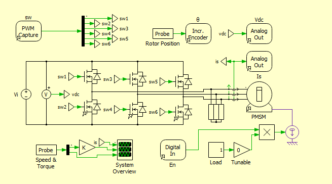
Figure 3: Power circuit of the PMSM drive system
You can download the Project files here: Download files now. (You must be logged in).
Figure 3 presents the power circuit of the PMSM drive system consists of a 24 V DC voltage source feeding a three-phase voltage source inverter (VSI) built with three MOSFET half-bridge modules. The inverter converts the DC supply into controlled AC voltages to drive the PMSM, with six PWM switching signals generated by a PWM Capture block. Key measurements—including DC-link voltage, stator currents, and rotor position—are acquired via Analog Output blocks and an Incremental Encoder for closed-loop control [2].
The mechanical dynamics of the PMSM are captured through its rotor inertia, which absorbs energy during acceleration and provides a natural load during startup and speed transients. For closed-loop operation, the applied load must not exceed 40% of the nominal motor torque; exceeding this limit prevents the observer from tracking rotor speed accurately, leading to control instability. To evaluate system performance under changing conditions, a load profile is implemented that alternates between 20% and 40% of the rated torque, with the load applied only after the controller has been activated to ensure a controlled startup sequence.
C. Rotor-Field Oriented Control
The stator current is regulated in the dq-frame using rotor-field oriented control. The voltage equations in the dq-reference frame are given by [1]:
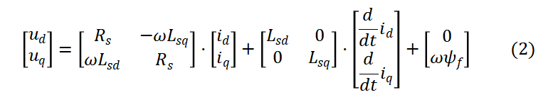
- u_d, u_q – Stator voltages in d-axis and q-axis of the rotor reference frame (V)
- R_s – Stator resistance per phase (Ω)
- ω – Electrical angular speed of the rotor (rad/s)
- L_sd, L_sq – d-axis and q-axis synchronous inductances (H); for surface-mount PMSM, L_sd ≈ L_sq
- i_d, i_q – Stator currents in d-axis (field-producing) and q-axis (torque-producing) (A)
- d/dt i_d, d/dt i_q – Derivative of dq-axis currents representing inductive voltage drops (A/s)
- ψ_f – Permanent magnet flux linkage (Wb); also denoted as ψ_m in some texts
III. Sensorless Control Algorithm
A. Observer Structure
A reduced-order observer is implemented in the γδ reference frame, which differs from the dq-frame by the position error θ_e. The estimated rotating γδ frame allows position error estimation from the extended EMF components [1]. The machine model in γδ coordinates including extended EMF is:
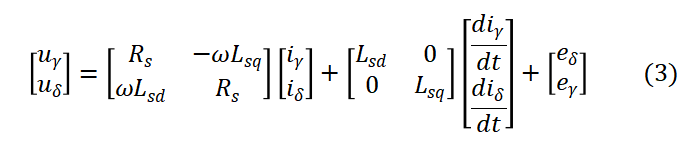
- u_γ, u_δ are the stator voltages in the estimated γ-axis and δ-axis of the rotating reference frame, measured in volts (V).
- R_s is the stator resistance per phase, which represents the copper losses in the windings, measured in ohms (Ω).
- ω is the electrical angular speed of the rotor, measured in radians per second (rad/s).
- L_sd and L_sq are the d-axis and q-axis synchronous inductances. L_sd is the direct axis magnetizing inductance, while L_sq is the quadrature axis inductance, both measured in henries (H).
- i_γ and i_δ are the stator currents in the estimated γδ reference frame, measured in amperes (A).
- d/dt i_γ and d/dt i_δ are the time derivatives of the γδ currents, representing the inductive voltage drops, measured in amperes per second (A/s).
- e_γ and e_δ are the extended electromotive force (EMF) components in the γ-axis and δ-axis, which contain the rotor position error information, measured in volts (V).
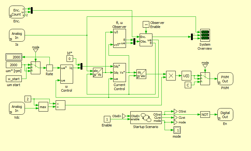
Figure 4: Controller model of the sensorless rotor-field oriented control
Figure 4 presents the controller model of the sensorless rotor-field oriented control (FOC) system, where stator currents are regulated in the dq-frame. The speed and rotor position are calculated either by the Observer subsystem or an Encoder Counter block, with a “Selector” block allowing the observer to be enabled or disabled. A higher-level speed controller implements the outer control loop, accepting a speed reference in rpm, while an “Enable” signal allows the complete controller to be activated or reset to open-loop operation with a fixed modulation index. A Rate Limiter provides robust system behavior by limiting abrupt speed changes, and a Digital Out is included for enabling/disabling when the Plant RT Box is replaced by actual hardware.
IV. Real-Time Implementation
The model is partitioned into two subsystems: “Plant” and “Controller”, allowing independent code generation for real-time simulation on two RT Boxes. For real-time operation, three 37-pin Sub-D cables connect the boxes front-to-front as shown in Figure 2. The plant subsystem runs on one RT Box while the controller executes on the second RT Box, minimizing execution time for each real-time target [2].
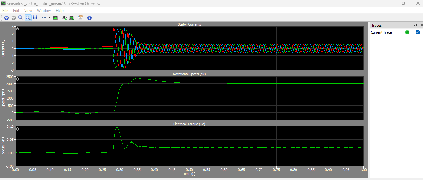
Figure 5: Plant system contains the Stator Currents, Rotational speed and Electrical Torque output graphs
You can download the Project files here: Download files now. (You must be logged in).
Figure 5 displays three key output graphs from the Plant subsystem: Stator Currents, Rotational Speed, and Electrical Torque. The Stator Currents graph shows the three-phase AC currents (i_a, i_b, i_c) supplied to the PMSM, indicating their sinusoidal waveform and amplitude variations during motor operation. The Rotational Speed graph plots the actual mechanical speed of the rotor in rpm, demonstrating how the motor responds to speed references and load disturbances over time. The Electrical Torque graph illustrates the developed electromagnetic torque (T_e) in Nm, showing transient peaks during acceleration and steady-state values under constant load conditions.
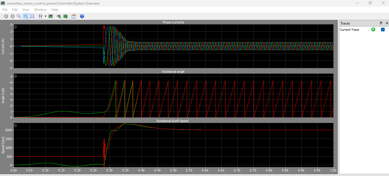
Figure 6: Controller blocks which provide us output graphs of phase currents, Rotational angle and Rotational shaft speed
Figure 6 presents output graphs from the Controller subsystem, including Phase Currents, Rotational Angle, and Rotational Shaft Speed. The Phase Currents graph displays the measured stator phase currents in the stationary reference frame, showing their magnitude and phase relationships used for the Clarke and Park transformations. The Rotational Angle graph plots both the actual rotor position (θ, measured by encoder) and the estimated rotor position (θ̂, from the observer) versus time, allowing comparison of observer accuracy. The Rotational Shaft Speed graph compares the measured speed (ω_m from encoder) with the estimated speed (ω̂_m from observer), demonstrating the observer’s tracking performance during startup, steady-state, and transient conditions such as step changes in speed reference.
For single RT Box applications, multi-tasking is enabled where the controller runs in a separate core as a Task frame block while the plant executes in the Base task on another core. This computational splitting enables higher sampling rates and improved real-time performance.
V. Results and Discussion
A. Load Disturbance Response
The load torque profile alternates between 0.04 Nm and 0.06 Nm (40% to 60% of nominal 0.1 Nm torque). As shown in Fig. 9, the current controller compensates for load changes within approximately 0.05 seconds. The resulting speed drop of approximately 200 rpm is fully compensated by the speed controller within 0.5 seconds, demonstrating robust disturbance rejection capabilities [2].
B. Speed Reference Step Response
A step change in speed reference from 1000 rpm to 2000 rpm was applied to evaluate transient performance. Fig. 10 presents the comparison between measured (encoder) and estimated (observer) angle and speed. The measured and estimated speeds match closely during steady-state operation. During rapid reference changes, small position and speed estimation errors occur, but these errors have negligible effect on motor control performance [2].
It is noted that the observer performs better at higher speeds. Below 1000 rpm, increased speed ripple becomes visible due to blanking time effects, though stable operation is maintained for speeds down to 500 rpm under load.
VI. Conclusion
This paper presented a complete sensorless vector control system for a permanent magnet synchronous machine (PMSM) drive, utilizing an observer-based approach for rotor position and speed estimation. The drive system, powered by a 24 V DC source and rated at 40 W with 0.1 Nm nominal torque, successfully demonstrated robust performance through both offline simulation and real-time implementation on the PLECS RT Box platform.
The cascaded control architecture, comprising inner dq-axis current controllers and an outer speed controller, effectively regulated torque and speed under various operating conditions. The reduced-order observer implemented in the γδ reference frame, based on extended electromotive force (EMF) estimation, successfully eliminated the need for physical encoders while providing accurate position and speed tracking. Experimental validation showed that the observer performs reliably at speeds down to 500 rpm, with load disturbances up to 40% of nominal torque being compensated within 0.5 seconds.
The dual RT Box configuration, with separate Plant and Controller subsystems, minimized execution time and enabled seamless transition between offline simulation, hardware-in-the-loop (HIL) testing, and rapid control prototyping (RCP). The model’s ability to run on single or dual RT Boxes with multi-tasking support demonstrated its flexibility for various real-time applications. While the observer exhibits slightly reduced accuracy below 1000 rpm due to blanking time effects, overall performance confirms that sensorless vector control is a viable and cost-effective alternative to encoder-based drives for medium to high-speed PMSM applications.
References
[1] S. Morimoto, K. Kawamoto, M. Sanada, and Y. Takeda, “Sensorless control strategy for salient-pole PMSM based on extended EMF in rotating reference frame,” IEEE Trans. Ind. Appl., vol. 38, no. 4, pp. 1054-1061, Jul./Aug. 2002.
[2] Plexim GmbH, “Sensorless Vector Control for Permanent Magnet Synchronous Machine,” RT Box Demo Model, Target Support Package 2.1.5, 2023.
[3] R. De Doncker, D. Pulle, and A. Veltman, Advanced Electrical Drives. Springer, 2011.
You can download the Project files here: Download files now. (You must be logged in).


Responses