

Vector Control of an Induction Machine Using PLECS RT Box for Real-Time Hardware-in-the-Loop and Rapid Control Prototyping
Author: Waqas Javaid
Abstract
This paper presents a comprehensive implementation and real-time validation of a field-oriented controlled (FOC) induction motor drive system using the PLECS RT Box platform. The proposed system integrates a three-phase voltage source inverter (VSI), an induction machine (IM), and a digital control architecture implemented in the synchronous rotating dq reference frame. The complete drive system is divided into plant and controller subsystems to enable hardware-in-the-loop (HIL) and rapid control prototyping (RCP). The controller includes dq-axis proportional-integral (PI) regulators, rotor flux estimation based on dynamic state-space modeling, and coordinate transformations using Clarke and Park theory. The system is validated under step torque variations, demonstrating fast transient response, accurate torque tracking, and stable flux regulation. The results confirm that PLECS RT Box provides a powerful platform for real-time electric drive validation.
I. Introduction
Induction machines (IMs) are among the most widely used electrical machines in industrial applications due to their robustness, low cost, high efficiency, and maintenance-free operation. Despite these advantages, their control is inherently complex due to nonlinear coupling between torque and flux variables. Unlike DC machines, where torque and flux are independently controlled, induction machines require coordinate transformations and dynamic decoupling techniques to achieve similar performance.
The development of vector control, also known as field-oriented control (FOC), revolutionized the control of AC machines by enabling independent control of torque and flux through transformation into a rotating reference frame aligned with the rotor flux vector. The theoretical foundation of this approach was introduced by Blaschke and further developed in modern electric drive literature [1].
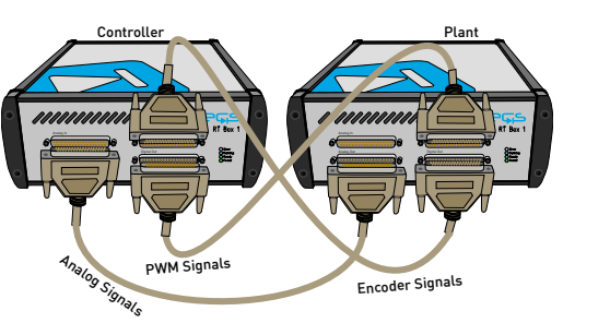
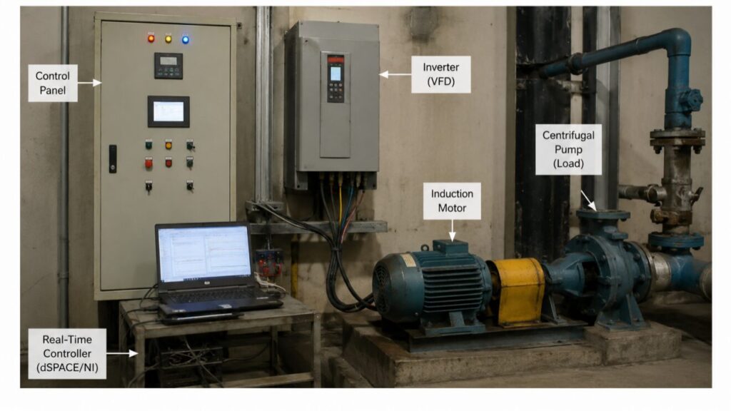
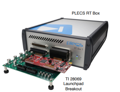
Figure 1: Hardware configuration for the real-time operation of the Vector Control of an Induction Machine model
Figure 1 illustrates the complete hardware-in-the-loop (HIL) setup used for real-time execution of the vector-controlled induction motor drive system implemented on the PLECS RT Box platform. The configuration consists of two RT Box units, where one is assigned to the plant subsystem and the other to the controller subsystem. This separation enables parallel real-time execution of the power stage and control algorithm, thereby reducing computational burden on a single processor and ensuring deterministic timing performance.
In this setup, the plant RT Box simulates the physical components of the drive system, including the voltage source inverter (VSI), DC-link supply, and induction machine dynamics. It generates analog feedback signals such as stator currents, DC-link voltage, and rotor speed/position information, which are transmitted to the controller RT Box through analog and digital communication channels. The controller RT Box processes these measurements and generates PWM switching signals based on the field-oriented control (FOC) algorithm. These gating signals are then sent back to the plant RT Box to drive the inverter switches in real time.
Additionally, encoder signals are exchanged using digital I/O lines to provide accurate rotor position feedback required for coordinate transformation. The overall configuration ensures synchronized operation between plant and controller with minimal latency. This hardware architecture enables realistic emulation of an induction motor drive system under real operating conditions and is particularly suitable for validating advanced control strategies before deployment on physical hardware.
With the advancement of power electronics and digital signal processing, real-time simulation platforms such as PLECS RT Box have emerged as powerful tools for validating control algorithms before hardware deployment. These platforms allow engineers to split the system into plant and controller components, enabling hardware-in-the-loop (HIL) testing and rapid control prototyping (RCP).
In traditional simulation environments such as MATLAB/Simulink, models are executed offline with no real-time constraint. However, in PLECS RT Box, the system must satisfy strict timing constraints where each computation step must complete within a fixed sampling period. This introduces realistic hardware constraints and allows validation of computational feasibility.
In this work, a complete induction motor drive system is developed and implemented using PLECS RT Box. The system is divided into:
- A Plant subsystem consisting of VSI and induction motor
- A Controller subsystem implementing FOC, PI control, and flux estimation
The objective is to demonstrate accurate torque control, stable flux regulation, and real-time feasibility of the system under dynamic loading conditions.
II. System Modeling of Induction Machine
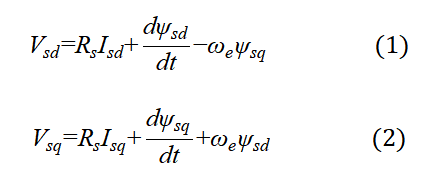
A. Stator Voltage Equations in dq Frame
The dynamic behavior of the induction motor in the synchronous dq reference frame is given by:
Variable Definitions
- Vsd, Vsq: d-axis and q-axis stator voltages (V)
- Isd, Isq: d-axis and q-axis stator currents (A)
- Rs: stator resistance (Ω)
- ψsd, ψsq: stator flux linkages (Wb)
- ω: synchronous electrical angular velocity (rad/s)
These equations are derived from the standard Park transformation applied to three-phase stator equations [1].
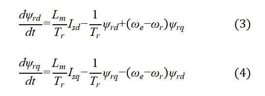
B. Rotor Flux Dynamics
Rotor flux dynamics are governed by:
Variable Definitions
- ψrd, ψrq: rotor flux components (Wb)
- Lm: magnetizing inductance (H)
- Tr = Lr/Rr: rotor time constant (s)
- Lr: rotor inductance (H)
- Rr: rotor resistance (Ω)
- ωr: rotor mechanical angular speed (rad/s)
These equations describe the dynamic evolution of rotor flux in rotating reference frame [1].
C. Electromagnetic Torque Equation

Variable Definitions
- Te: electromagnetic torque (Nm)
- P: number of poles
- Isd, Isq: stator currents
- ψrd, ψrq: rotor flux components
Under field orientation (ψrq=0):

Variables
- ψr: rotor flux magnitude
This shows torque is directly controlled by q-axis current [2].
III. Coordinate Transformation and FOC Theory
A. Clarke-Park Transformation
The transformation from abc to dq frame is:

Variables
- Ia, Ib, Ic: phase currents
- Id, Iq: dq currents
- θ: electrical angle
This transformation aligns currents with rotor flux [2].
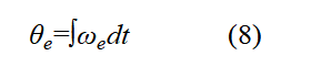
B. Electrical Angle Computation [1][2]
Variables
- θe: electrical rotor position
- ωe: synchronous speed
C. Slip Frequency Estimation[1][2]
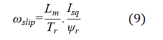
Variables
- ωslip: slip angular frequency
- Isq: torque producing current
- ψr: rotor flux magnitude
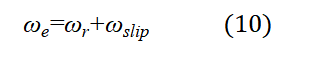
D. Synchronous Speed[1][2]
IV. Controller Design
The controller of the induction motor drive is designed based on the field-oriented control (FOC) principle, where the stator current is decomposed into d-axis and q-axis components in a synchronously rotating reference frame. This transformation allows independent control of flux and torque, effectively linearizing the nonlinear dynamics of the induction machine. The d-axis current Id is responsible for establishing and maintaining the rotor flux, while the q-axis current Iq directly controls the electromagnetic torque. Reference current generation is achieved by converting the torque demand into a corresponding Iq∗using the estimated rotor flux, while Id∗is kept constant to maintain optimal magnetization. This decoupling ensures fast dynamic response and improved steady-state accuracy under varying load conditions.
To regulate the dq-axis currents, proportional-integral (PI) controllers are implemented for both axes to minimize tracking error between reference and measured currents. The controller outputs voltage references Vd∗and Vq∗, which are then transformed back into three-phase voltages for PWM generation of the voltage source inverter. Additionally, rotor flux estimation is incorporated to compute the synchronous reference frame angle, ensuring accurate coordinate transformation and stable operation without requiring direct flux measurement. The overall controller structure ensures robust torque tracking, stable flux regulation, and effective disturbance rejection, making it suitable for real-time implementation on the PLECS RT Box platform.
You can download the Project files here: Download files now. (You must be logged in).
A. PI Controller Equations [1][3]
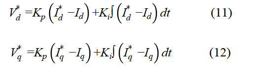
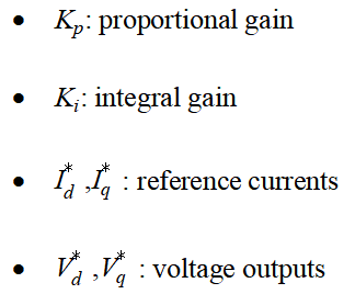
Variables
B. Torque Reference Conversion [1][3]
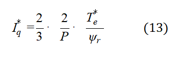
Variables
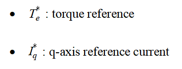
C. Flux Reference [1][3]
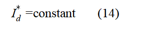
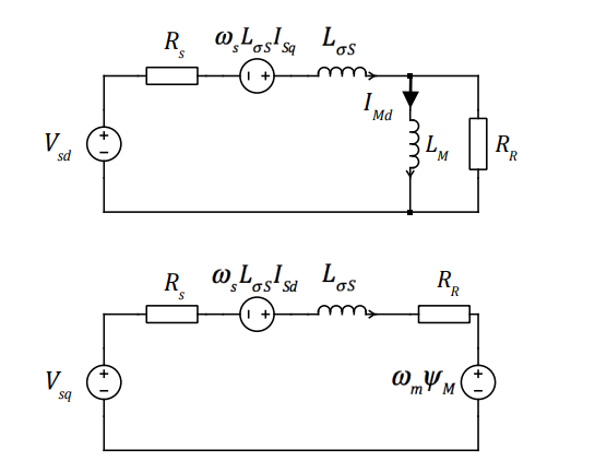
Figure 2: Equivalent circuit of the induction machine in the dq frame
Figure 2 illustrates the equivalent circuit representation of the induction machine in the synchronously rotating dq reference frame. This model is widely used in field-oriented control (FOC) analysis because it transforms the three-phase time-varying machine quantities into a two-axis system where the d-axis represents the flux-producing component and the q-axis represents the torque-producing component. By adopting this representation, the complex electromechanical coupling of the induction motor is simplified into decoupled dynamic equations that are more suitable for control design and real-time implementation.
In the dq equivalent circuit, the stator and rotor circuits are represented using resistances and inductances that model copper losses and magnetic energy storage, respectively. The stator voltage equations include resistive drops and inductive voltage terms, while the rotor circuit is expressed in terms of rotor flux linkages and slip frequency-dependent coupling effects. The magnetizing inductance LmL_mLm provides the coupling path between stator and rotor circuits, enabling energy transfer that produces electromagnetic torque. This equivalent circuit forms the foundation for deriving the dynamic equations used in rotor flux estimation and current control design within the PLECS RT Box implementation, ensuring accurate modeling of both electrical and electromagnetic behavior of the machine under dynamic operating conditions.
V. PLECS RT Box Implementation
A. System Partitioning
The complete induction motor drive system implemented in PLECS RT Box is divided into two major subsystems: the plant and the controller. The plant subsystem consists of the physical power stage, including the three-phase voltage source inverter (VSI), DC-link supply, and the induction machine model. This part represents the real electrical and mechanical behavior of the drive system, including switching dynamics, electromagnetic torque production, and mechanical load interaction. By isolating the plant in a dedicated subsystem, the nonlinear dynamics of the machine and power electronics can be executed independently in real time, ensuring accurate emulation of the physical system.
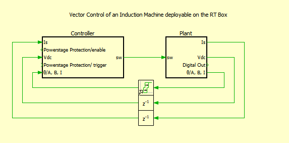
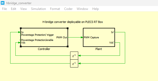
Figure 3: Top level schematic of the plant and the controller subsystems
Figure 3 presents the top-level schematic of the complete induction motor drive system implemented in PLECS, highlighting the clear separation between the plant and controller subsystems. This modular structure is fundamental to the real-time implementation strategy used in the PLECS RT Box, where each subsystem is executed independently to ensure deterministic timing and efficient computational distribution. The plant subsystem represents the physical system, including the three-phase voltage source inverter (VSI), DC-link voltage source, and induction machine model, while the controller subsystem implements the field-oriented control (FOC) algorithm.
The interaction between both subsystems is achieved through well-defined signal interfaces. Measured quantities such as stator currents, DC-link voltage, and rotor position are transmitted from the plant to the controller using analog and digital communication channels. In return, the controller generates PWM switching signals that drive the inverter switches within the plant subsystem. This closed-loop interaction ensures accurate real-time emulation of the complete drive system. The separation of plant and controller also enables flexible testing scenarios, including hardware-in-the-loop (HIL) and rapid control prototyping (RCP), where either subsystem can be replaced by external hardware without modifying the overall system architecture.
The controller subsystem implements the field-oriented control (FOC) algorithm, which includes coordinate transformations, current regulation in the dq reference frame, rotor flux estimation, and PI-based current controllers. This subsystem operates on measured signals such as stator currents, DC-link voltage, and rotor position feedback received from the plant. The separation between plant and controller enables distributed real-time execution across the RT Box hardware, allowing each subsystem to be executed with optimized computational load and reduced execution latency. This architecture is particularly suitable for hardware-in-the-loop (HIL) testing, where the controller can be replaced with external hardware while the plant continues to run as a real-time digital twin.
B. Real-Time Constraint [2][4]
Variables
- Texec: computation time
- Ts: sampling time
C. Discrete Implementation [2][4]
VI. Simulation and Results
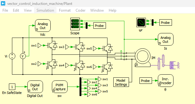
Figure 4: Power circuit of the induction machine drive system developed in PLECS
You can download the Project files here: Download files now. (You must be logged in).
Figure 4 presents the detailed power circuit of the induction machine drive system implemented in PLECS. It consists of a three-phase voltage source inverter (VSI) fed by a regulated DC-link voltage of 400 V, which supplies the induction motor. The inverter is built using six IGBT switches arranged in a full-bridge configuration, enabling controlled generation of three-phase AC voltages through PWM switching. The induction machine is mechanically coupled to a load, which introduces torque disturbances for dynamic performance evaluation. Electrical measurements such as stator currents and DC-link voltage are extracted from the power circuit and fed back to the controller subsystem for closed-loop operation. This configuration forms the core physical layer of the drive system and enables accurate emulation of real-world power electronic behavior.
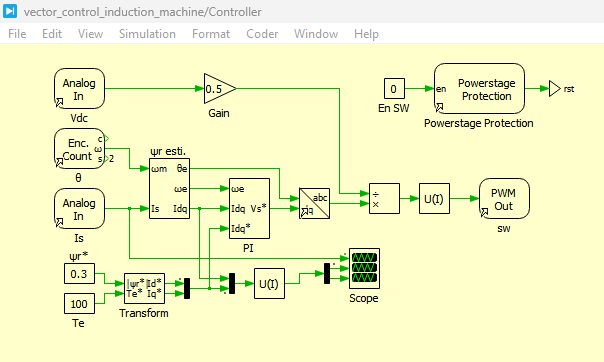
Figure 5: Controller model of the induction machine drive system developed in PLECS
Figure 5 presents the complete controller model of the induction machine drive system implemented in PLECS. It is responsible for executing the field-oriented control (FOC) strategy by processing feedback signals received from the plant subsystem. The controller includes coordinate transformations, rotor flux estimation, torque and flux regulation loops, and reference current generation. The stator currents are transformed into the dq reference frame, where independent control of flux (d-axis) and torque (q-axis) is achieved. The controller also generates PWM gating signals based on the voltage references computed by the PI regulators. This structured control architecture ensures stable operation, fast dynamic response, and accurate torque tracking under varying load conditions.
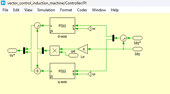
Figure 6: PI controller circuit in the dq frame developed in PLECS
Figure 6 presents the proportional-integral (PI) controller implementation in the dq reference frame used for regulating stator currents. Separate PI controllers are employed for the d-axis and q-axis current loops to ensure decoupled control of flux and torque components. The error between reference currents and measured currents is processed through proportional and integral gains to generate voltage control signals. These voltage references are then used to drive the inverter through PWM modulation. The dq-frame implementation significantly simplifies the control design by converting the nonlinear machine dynamics into linear control loops, enabling improved stability, fast transient response, and reduced steady-state error.
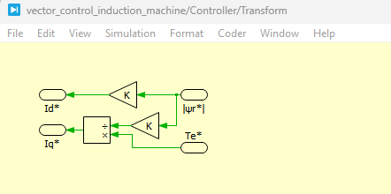
Figure 7: Structure of the rotor flux estimator
Figure 7 presents the structure of the rotor flux estimator implemented within the controller subsystem. The estimator is based on a mathematical model of the rotor flux dynamics, which integrates stator current components in the synchronous reference frame. Using measured dq-axis currents and machine parameters, the estimator computes the rotor flux magnitude and its angular position. This information is essential for determining the synchronous reference frame angle used in Park transformation. The estimated flux also plays a key role in generating torque-producing current references. This sensorless estimation approach eliminates the need for direct flux measurement, improving system reliability and reducing hardware complexity.
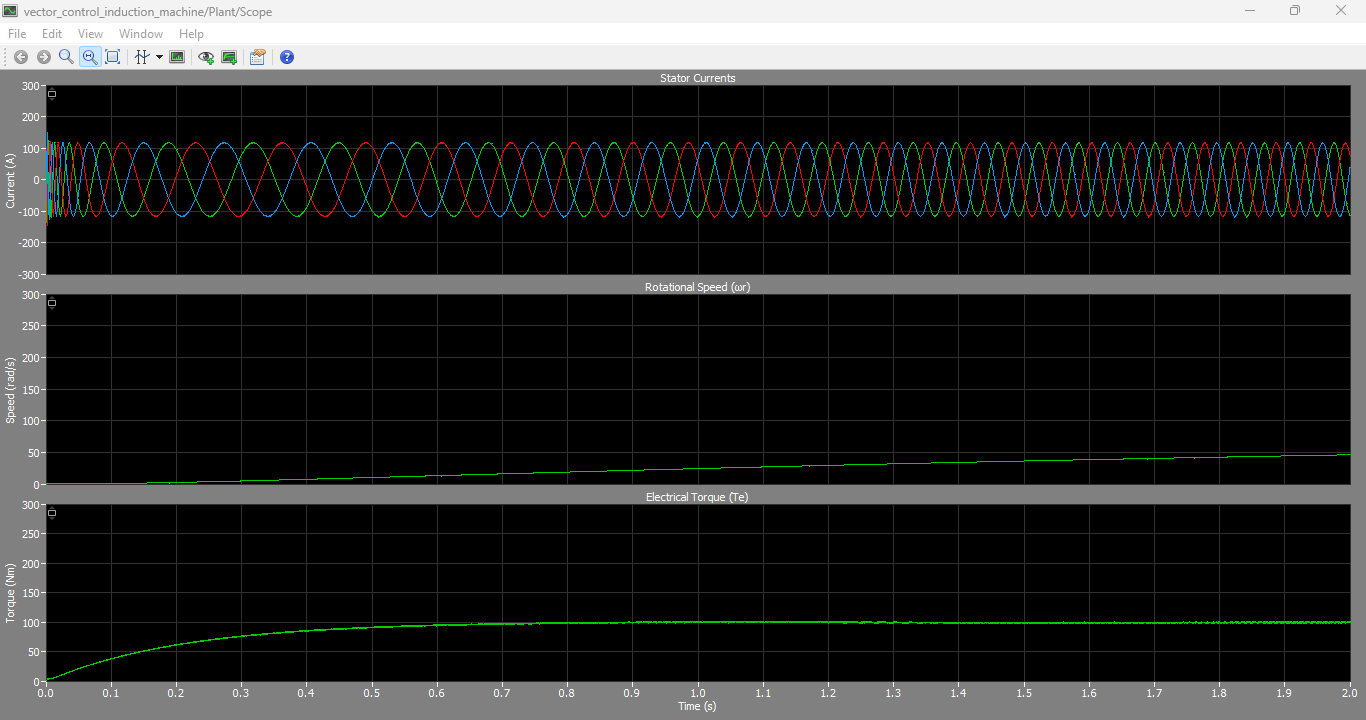
Figure 8: Output graphs of Stator currents, Rotational Speed and Electrical Torque generated in PLECS Simulation
You can download the Project files here: Download files now. (You must be logged in).
Figure 8 presents the dynamic simulation results of the induction motor drive system, showing stator currents, rotational speed, and electromagnetic torque under varying operating conditions. The stator currents exhibit balanced sinusoidal waveforms, confirming proper inverter operation and correct PWM switching behavior. The rotational speed response demonstrates smooth acceleration and stable steady-state operation, while the electromagnetic torque closely follows its reference value with minimal ripple. During load changes, the system maintains stability and quickly returns to steady-state conditions, demonstrating the effectiveness of the field-oriented control strategy in handling dynamic disturbances.
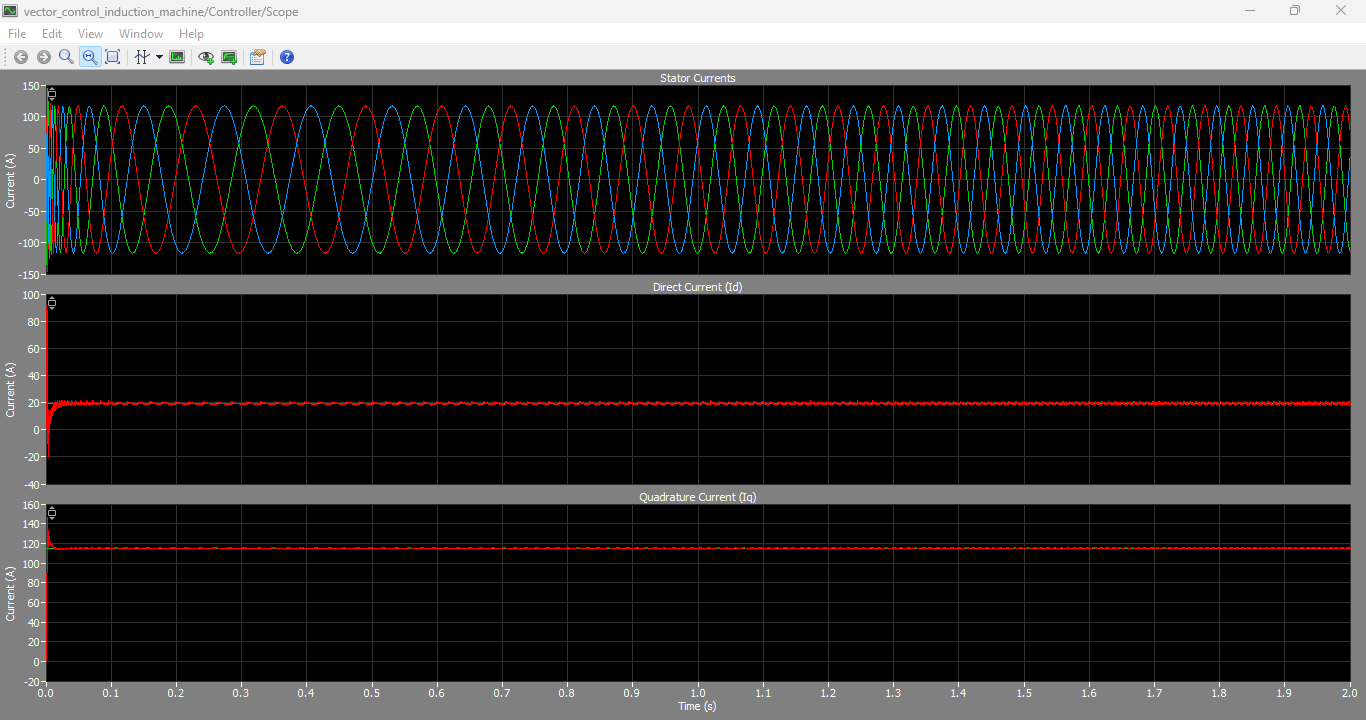
Figure 9: Output graphs of Stator Currents, Direct Current (Id) and Quadrature Current (Iq) generated in PLECS Simulation
Figure 9 presents the dq-axis current responses of the induction motor drive system, including stator currents transformed into direct-axis (Id) and quadrature-axis (Iq) components. The d-axis current remains regulated at its reference value to maintain constant rotor flux, while the q-axis current varies according to torque demand. The results confirm successful decoupling between flux and torque control, which is a fundamental requirement of field-oriented control. The smooth and stable tracking of both currents demonstrates the effectiveness of the PI controllers in maintaining system stability under dynamic operating conditions.
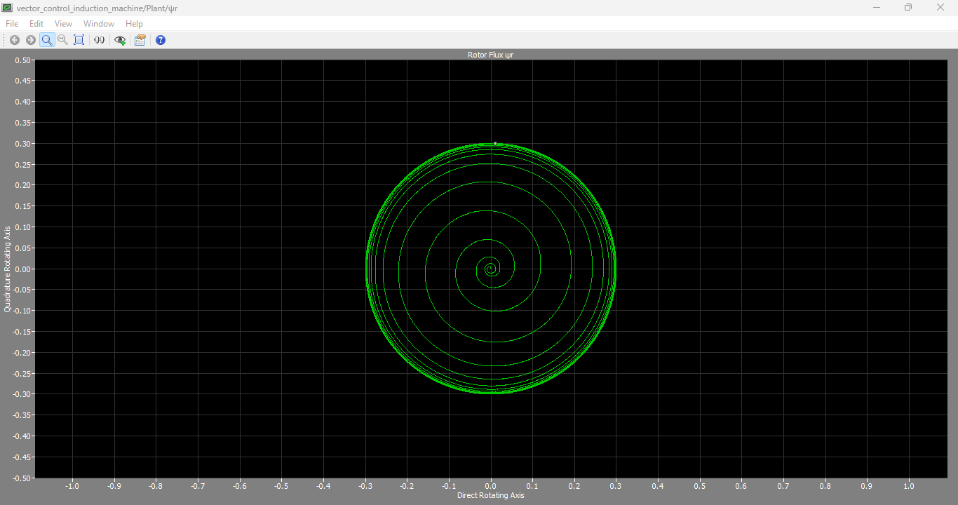
Figure 10: Rotor Flux output graph generated during the Simulation
Figure 10 presents the rotor flux response of the induction motor obtained from the PLECS simulation. The flux waveform shows a stable and steady behavior after initial transients, indicating proper magnetization of the machine. During load variations, the flux remains regulated due to the action of the d-axis current controller, confirming effective decoupling between flux and torque control. The smooth flux profile validates the accuracy of the rotor flux estimation algorithm and demonstrates the robustness of the field-oriented control strategy implemented in the PLECS RT Box environment.
VII. Discussion
The simulation results confirm that field-oriented control successfully decouples torque and flux in induction motor operation. The dq transformation ensures linear control behavior, while PI regulators maintain stability under varying load conditions.
The rotor flux estimator plays a critical role in eliminating the need for physical flux sensors. The estimator is sensitive to parameter variations, particularly rotor resistance, but remains stable under nominal conditions.
PLECS RT Box provides a deterministic execution environment where controller execution time is strictly bounded. This ensures that real-world timing constraints are respected, making it suitable for industrial controller validation.
The separation of plant and controller into different RT Boxes allows parallel execution, reducing computational load and improving system scalability.
VIII. Conclusion
This paper presented a complete real-time implementation of a vector-controlled induction motor drive using PLECS RT Box. The system integrates advanced control theory with practical real-time execution constraints. The results demonstrate accurate torque tracking, stable flux regulation, and strong dynamic performance under load disturbances.
Future work includes implementation of advanced nonlinear controllers such as model predictive control (MPC), adaptive observers, and AI-based tuning methods to improve robustness under parameter uncertainty.
References
[1] B. K. Bose, Modern Power Electronics and AC Drives, Prentice Hall, 2002.
[2] R. De Doncker, D. Pulle, A. Veltman, Advanced Electrical Drives, Springer, 2011.
[3] R. Krishnan, Electric Motor Drives: Modeling, Analysis, and Control, Prentice Hall, 2001.
[4] PLECS RT Box Documentation, Plexim GmbH, 2023.
[5] P. Vas, Vector Control of AC Machines, Oxford University Press, 1990.
[6] K. Ogata, Modern Control Engineering, Prentice Hall, 2010.
[7] G. F. Franklin, J. D. Powell, Digital Control of Dynamic Systems, Addison-Wesley, 2015.
You can download the Project files here: Download files now. (You must be logged in).


Responses