

Real-Time Hardware-in-the-Loop Implementation of a Current-Controlled H-Bridge Converter Using PLECS RT Box
Author: Waqas Javaid
Abstract
This paper presents the modeling, implementation, and real-time validation of a current-controlled H-bridge converter developed in the PLECS simulation environment using the PLECS RT Box platform. The proposed system consists of a full-bridge DC–DC converter supplying an inductive RL load under closed-loop proportional–integral (PI) current control. The complete system is divided into plant and controller subsystems, enabling independent execution for hardware-in-the-loop (HIL) testing and rapid control prototyping (RCP). The plant subsystem contains the H-bridge converter, current sensing circuitry, and voltage sensing models, while the controller subsystem includes digital PI current regulation, duty-cycle generation, PWM control, and protection logic. Real-time implementation is performed using two RT Boxes communicating through analog and digital interfaces. The converter is supplied with a 24 V DC source and operates at a switching frequency of 10 kHz. The experimental and simulation results demonstrate stable current tracking, effective switching operation, and reliable real-time execution without timing violations. The proposed implementation validates the capability of the PLECS RT Box platform for high-fidelity real-time power electronics simulation and embedded control verification.
I. Introduction
Power electronic converters are essential components in modern electrical and industrial systems due to their ability to efficiently regulate and control electrical energy. Among the most widely used converter topologies is the H-bridge converter, which is extensively applied in motor drives, DC–DC conversion systems, battery-powered applications, robotics, electric vehicles, renewable energy systems, and industrial automation. The H-bridge converter provides bidirectional voltage control across the load, enabling flexible operation for inductive and resistive loads under different operating conditions.
The increasing complexity of modern power electronic systems has created a growing demand for advanced simulation and real-time validation platforms. Traditional offline simulation tools are effective for initial analysis; however, they are often insufficient for validating real-time behavior, timing constraints, switching delays, and embedded controller interactions. Hardware-in-the-loop (HIL) simulation has emerged as an effective solution for overcoming these limitations by enabling real-time interaction between simulated power stages and actual embedded controllers. This approach reduces hardware development risks, minimizes testing costs, and improves controller reliability before deployment on physical systems.
The PLECS RT Box platform provides a high-performance real-time simulation environment specifically designed for power electronics and electrical drive applications. It enables accurate real-time execution of converter models using fixed-step discretization and deterministic timing. In addition, the platform supports external controller integration, analog and digital signal interfacing, and rapid prototyping capabilities. These features make the RT Box highly suitable for validating converter control strategies in real-time conditions.
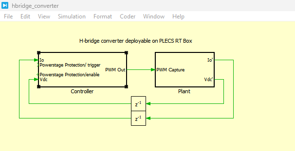
Figure 1: H-Bridge Converter development in PLECS schematics
Figure 1 presents the complete H-Bridge converter developed in the PLECS simulation environment for real-time hardware-in-the-loop implementation. The schematic consists of two major subsystems namely the plant subsystem and the controller subsystem. The plant subsystem contains the DC voltage source, full-bridge power converter, inductive RL load, voltage sensing blocks, current sensing blocks, and PWM capture interface. The H-bridge converter is supplied with a 24 V DC source and operates using pulse-width modulation signals generated by the controller. The inductive load is modeled using resistance and inductance elements to represent practical electrical load behavior. Analog output blocks are used to export the measured current and voltage signals from the plant subsystem for controller feedback and real-time monitoring purposes.
The figure 1 also illustrates the controller subsystem responsible for closed-loop current regulation of the H-bridge converter. The controller receives the sensed inductor current and DC-link voltage through analog input blocks and processes these signals using a proportional–integral (PI) current control algorithm. The controller compares the measured current with the reference current and generates PWM duty cycles accordingly. PWM output blocks transmit switching pulses to the converter switches to regulate the load current dynamically. Protection logic, enable/disable switching control, and anti-windup mechanisms are also incorporated within the controller to ensure safe converter operation during transient conditions and startup procedures. The overall schematic demonstrates the integration of power electronics modeling, digital control implementation, and real-time execution capability in the PLECS RT Box environment.
In this work, a complete H-bridge converter system is developed in PLECS and implemented on the PLECS RT Box platform. The converter supplies an inductive RL load and employs a discrete proportional–integral (PI) current controller to regulate the load current. The system is divided into plant and controller subsystems to facilitate independent execution on separate RT Boxes. The controller generates PWM switching signals based on the current error, while voltage and current sensing circuits emulate real hardware measurement conditions. The study focuses on the real-time implementation, controller design, signal scaling, and dynamic performance evaluation of the converter system.
II. Mathematical Modeling of the H-Bridge Converter
The H-bridge converter used in this work consists of four controlled switching devices arranged in a full-bridge configuration. The converter is supplied by a DC voltage source and drives an RL load. The converter output voltage polarity is controlled by complementary switching of the bridge legs.
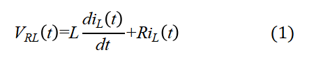
The electrical dynamics of the RL load are governed by the differential equation given in (1), which relates the converter output voltage to the inductor current dynamics and resistive voltage drop [1], [3].
where:

Equation (1) represents the fundamental dynamic behavior of the inductive load supplied by the H-bridge converter. The inductance opposes rapid changes in current, while the resistor dissipates energy in the form of heat. This equation is used in the controller design process to determine the plant transfer function and analyze current dynamics.
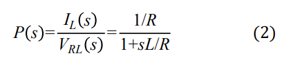
The transfer function of the RL load can be expressed as [3]:
where:
- P(s)= transfer function of the plant
- I_L(s)= Laplace transform of inductor current
- V_RL(s)= Laplace transform of load voltage
- s= Laplace variable
- L/R= electrical time constant of the RL load
Equation (2) shows that the RL load behaves as a first-order dynamic system. The plant transfer function is used for designing the PI current controller according to the magnitude optimum criterion. The transfer function also helps determine system bandwidth, transient response, and stability characteristics.
III. Controller Design
The H-bridge converter employs a closed-loop current control strategy using a proportional–integral (PI) controller. The primary objective of the controller is to regulate the inductor current by minimizing the error between the reference current and the measured load current. The current reference is periodically toggled between positive and negative values, enabling bidirectional current flow through the inductive load.
The controller subsystem receives scaled current and voltage measurements from the plant through analog input channels. These measured signals are inversely scaled to recover their actual physical values before entering the control loop. The measured inductor current is compared with the reference current, and the resulting error signal is processed by the PI compensator. The proportional component improves the dynamic response speed, while the integral component eliminates steady-state error and ensures accurate tracking performance.
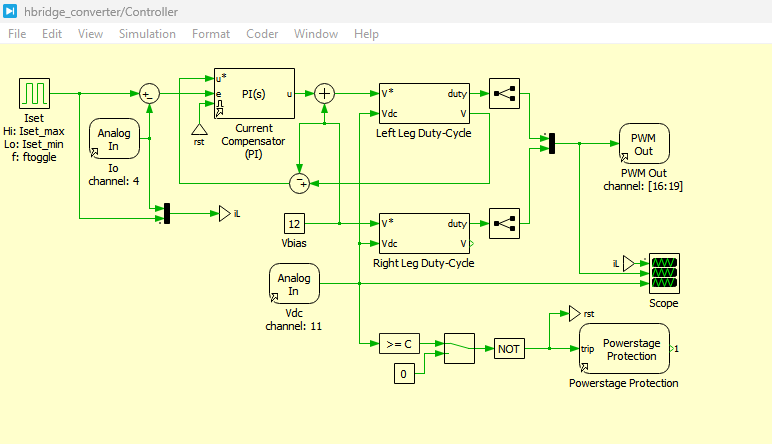
Figure 2: Controller design schematics of H-bridge converter in PLECS
You can download the Project files here: Download files now. (You must be logged in).
Figure 2 presents the controller design schematics of the H-bridge converter implemented in the PLECS simulation environment. The controller subsystem is responsible for regulating the inductor current of the converter through a closed-loop proportional–integral (PI) control strategy. The schematic includes analog input blocks, current reference generation, current compensator blocks, PWM generation logic, and protection mechanisms required for stable operation of the converter system. The measured inductor current and DC-link voltage from the plant subsystem are received through analog input channels and processed within the control algorithm. These measured signals are inversely scaled to recover the actual physical values before entering the controller loop.
The figure 2 further illustrates that the reference current signal is compared with the sensed inductor current to generate a current error signal. This error is processed by the PI current compensator, which produces the modulation command required for converter switching. The proportional part of the controller improves the transient response speed, while the integral component minimizes steady-state current error and enhances tracking accuracy. The generated controller output is then converted into duty-cycle commands for the PWM output block, which produces switching pulses for the H-bridge converter switches operating at a fixed switching frequency. The controller also includes anti-windup protection, enable/disable switching logic, and power-stage protection blocks to ensure safe operation during startup, shutdown, and abnormal operating conditions. Overall, the controller schematic demonstrates the complete digital current regulation strategy used for real-time control of the H-bridge converter in the PLECS RT Box platform.
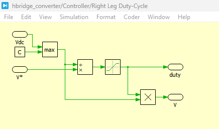
Figure 3: Right leg duty cycle circuit in PLECS simulation
Figure 3 presents the right leg duty-cycle circuit implemented in the PLECS simulation environment for the H-bridge converter control system. The purpose of this subsystem is to generate the duty cycle for the right leg of the H-bridge converter while maintaining a controlled average output voltage. The circuit receives the measured DC-link voltage as an input and calculates the required duty ratio to maintain the desired switching operation under varying supply conditions. This subsystem compensates for fluctuations in the input DC voltage to ensure stable converter performance and balanced bridge operation. The generated duty-cycle signal is then forwarded to the PWM output block, which produces the corresponding gating pulses for the right-leg switching devices of the H-bridge converter.
The figure 3 also demonstrates that the right leg operates as a reference voltage generation stage within the converter structure. The duty-cycle generation process helps maintain proper voltage polarity across the RL load during converter operation. The subsystem is implemented using arithmetic blocks, gain blocks, and PWM modulation logic within the PLECS environment, allowing real-time execution on the RT Box platform. The right-leg duty-cycle control contributes to stable current regulation, reduced switching disturbances, and improved converter response during dynamic operating conditions.
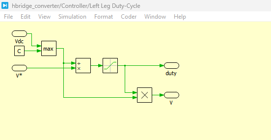
Figure 4: left leg duty cycle circuit in PLECS simulation
Figure 4 presents the left leg duty-cycle circuit implemented in the PLECS simulation environment for closed-loop current regulation of the H-bridge converter. This subsystem is responsible for generating the modulation signal for the left leg of the H-bridge based on the output of the proportional–integral (PI) current controller. The measured inductor current is compared with the reference current to generate a current error signal, which is processed by the PI compensator. The controller output determines the required duty cycle needed to regulate the current flowing through the inductive load.
The figure 4 further illustrates the integration of current feedback, PI compensation, saturation limits, and PWM generation logic within the left-leg control subsystem. The proportional component improves transient response speed, while the integral component eliminates steady-state error and ensures accurate current tracking performance. Anti-windup protection is incorporated to prevent excessive integral accumulation during saturation conditions. The generated duty-cycle signal is supplied to the PWM output block, which creates switching pulses for the left-leg power switches of the H-bridge converter. The left-leg duty-cycle circuit therefore plays a critical role in maintaining stable current regulation, minimizing current ripple, and improving the dynamic response of the converter system during real-time operation.
The controller design is based on the magnitude optimum criterion described in [3]. In this method, the dominant pole of the plant transfer function is canceled by selecting appropriate controller parameters. Small time delays introduced by PWM generation, signal sampling, and control calculation are combined into a single equivalent time constant to simplify controller tuning. This approach provides a well-damped system response with stable current regulation and minimal overshoot.
The PWM generation logic converts the controller output into switching duty cycles for the H-bridge converter. The right leg of the H-bridge maintains a fixed average voltage bias, while the left leg is actively modulated by the PI controller. The PWM switching frequency is set to 10 kHz, ensuring sufficient current control bandwidth and reduced ripple in the inductor current waveform.
The controller also includes protection and enable/disable logic for safe converter operation. During startup or fault conditions, the PWM outputs can be disabled, forcing the converter into a safe state. In addition, anti-windup protection is incorporated within the PI controller to prevent excessive integral accumulation during saturation conditions.
IV. System Architecture in PLECS
The complete H-bridge converter system is implemented in PLECS using a modular architecture composed of separate plant and controller subsystems. This separation allows independent code generation and execution on dedicated RT Box hardware.
The plant subsystem contains the full-bridge converter, DC voltage source, RL load, analog output scaling blocks, and PWM capture interface. The converter is modeled using a full-bridge power module configured with sub-cycle averaged switching behavior for real-time execution efficiency. The plant also includes voltage and current sensing circuits that emulate the characteristics of practical hardware measurement systems.
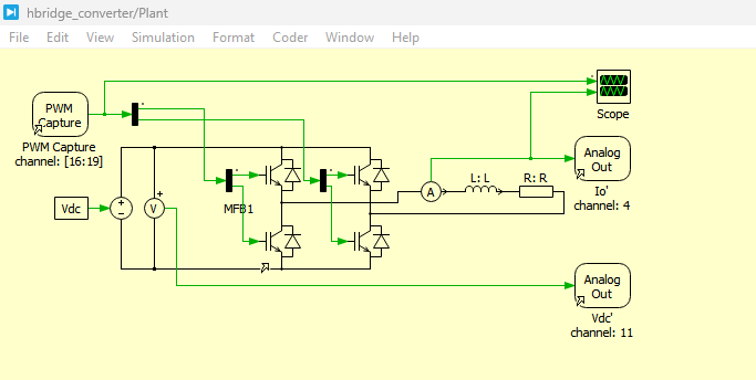
Figure 5: Power Plant circuit design of H-Bridge in PLECS Simulation
You can download the Project files here: Download files now. (You must be logged in).
Figure 5 presents the power plant circuit design of the H-bridge converter developed in the PLECS simulation environment. The power circuit consists of a 24 V DC voltage source, a full-bridge converter module, an RL inductive load, PWM capture blocks, and analog output measurement interfaces. The H-bridge converter is implemented using a full-bridge power module configured with one switching cell to emulate practical switching behavior in real-time operation. The converter receives PWM gating pulses from the controller subsystem through the PWM Capture block, which controls the switching states of the bridge transistors to regulate the output current flowing through the inductive load.
The figure 5 also shows that the converter output is connected to an inductive load composed of resistance R and inductance L, representing practical electrical load characteristics. The inductive load smooths the converter current and stores energy during switching transitions. Analog output blocks are used to measure and export the DC-link voltage and load current signals from the plant subsystem to the controller subsystem. These measured signals are scaled according to practical embedded hardware sensing requirements before transmission to the controller. The overall plant model is designed for fixed-step real-time execution on the PLECS RT Box platform, enabling accurate hardware-in-the-loop simulation of the H-bridge converter system.
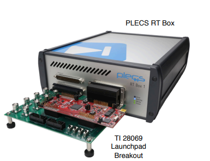
The voltage sensing circuit scales the measured DC voltage to match the analog-to-digital converter (ADC) voltage range of embedded controllers. Similarly, the current sensing circuit applies gain and offset scaling according to the specifications of the TI DRV8305EVM BoosterPack hardware [2]. These scaling circuits ensure that the RT Box outputs replicate realistic hardware sensor behavior.
The controller subsystem contains analog input blocks, PI current regulator, PWM output blocks, switching enable logic, and current reference generation. The subsystem processes the measured current and voltage signals and generates appropriate PWM gating signals for the converter switches. Both subsystems are configured for fixed-step real-time execution to satisfy deterministic timing requirements.
V. PLECS RT Box Implementation
The real-time implementation of the H-bridge converter is performed using two PLECS RT Boxes. One RT Box executes the plant subsystem while the second RT Box executes the controller subsystem. The separation of computational tasks reduces processor loading and improves real-time performance.
Communication between the RT Boxes is achieved through analog and digital signal interfaces. Analog outputs from the plant transmit scaled current and voltage measurements to the controller RT Box. In return, the controller sends PWM switching signals through digital outputs to the plant subsystem. This bidirectional signal exchange enables closed-loop current control in real time.

Figure 6: Performance overview for the execution on two RT Boxes
Figure 6 presents the performance overview for the execution of the H-bridge converter model on two PLECS RT Boxes during real-time simulation. The figure illustrates the relationship between the discretization step size and the processor execution time for both the plant and controller subsystems. The plant subsystem, which includes the power electronic converter and inductive load model, requires a higher computational effort because of the fast-switching behavior and real-time electrical calculations involved in the simulation. In contrast, the controller subsystem requires comparatively lower processor utilization since it mainly executes the PI current controller, PWM generation logic, and signal processing algorithms. The execution time results demonstrate that the real-time simulation operates within the allowable timing constraints of the RT Box hardware without processor overloading.
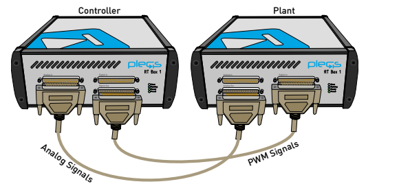
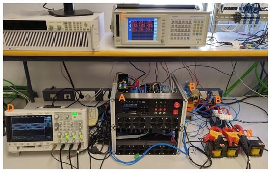
Figure 7: Hardware configuration for the real-time operation with two RT Boxes
Figure 7 presents the hardware configuration used for the real-time operation of the H-bridge converter system with two PLECS RT Boxes. One RT Box is configured to execute the plant subsystem, while the second RT Box executes the controller subsystem. The two RT Boxes communicate through analog and digital signal interfaces using DB37 cables connected front-to-front. The plant RT Box transmits measured analog signals such as DC-link voltage and inductor current to the controller RT Box through analog output channels. These feedback signals are used by the controller subsystem for closed-loop current regulation.
The RT Box platform uses a fixed-step solver with a discretization step size of 2 μs for the plant subsystem. The execution time of the real-time model remains within the sampling interval, ensuring stable operation without timing overruns. The multitasking capability of RT Box 2 and RT Box 3 further improves computational efficiency by distributing plant and controller execution across separate processing cores.
External Mode functionality enables online monitoring and parameter tuning during real-time execution. The current reference can be modified during operation without rebuilding the model, demonstrating the parameter inlining capability of the PLECS RT Box environment. This feature is particularly useful for rapid testing and controller optimization.
VI. Results and Discussion
The simulation and real-time execution results validate the effectiveness of the proposed H-bridge converter system implemented using the PLECS RT Box platform. The converter successfully regulates the inductor current according to the reference signal under both positive and negative current transitions.
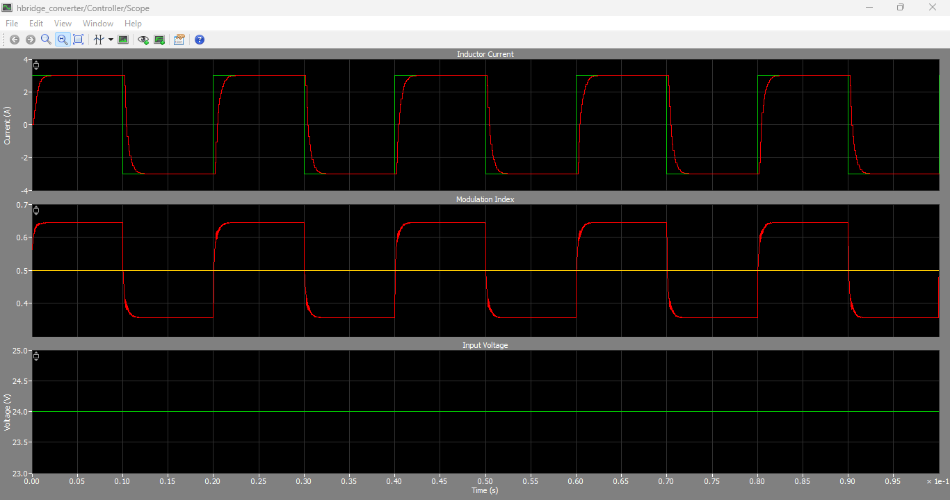
Figure 8: Inductor currents, Modulation Index and Input voltage output wave forms.
You can download the Project files here: Download files now. (You must be logged in).
Figure 8 presents the output waveforms of the inductor current, modulation index, and input voltage generated during the real-time simulation of the H-bridge converter in the PLECS environment. The inductor current waveform demonstrates the dynamic response of the closed-loop current control system as the current reference changes between positive and negative operating conditions. The waveform shows smooth current transitions with controlled ripple, confirming the effectiveness of the proportional–integral (PI) controller in regulating the load current. The inductive nature of the RL load helps reduce sudden current variations and contributes to stable converter operation during switching transitions.
The figure 8 also illustrates the modulation index waveform produced by the controller subsystem. The modulation index varies according to the current error and determines the duty cycle applied to the PWM generation block. During transient conditions, the modulation index changes dynamically to increase or decrease the converter output voltage, thereby forcing the inductor current to follow the reference signal. Once steady-state operation is achieved, the modulation index stabilizes at the required operating value needed to maintain the desired current level. This behavior validates the proper functioning of the digital current control algorithm and PWM switching strategy implemented in the controller.
In addition, the input voltage waveform confirms that the DC-link voltage supplied to the H-bridge converter remains stable during converter operation. Minor fluctuations may appear because of switching activity and dynamic load conditions; however, the voltage remains within the expected operating range throughout the simulation. The combined analysis of the inductor current, modulation index, and input voltage waveforms demonstrates stable closed-loop performance, accurate PWM control, and reliable real-time execution of the H-bridge converter system on the PLECS RT Box platform.
The inductor current waveform demonstrates accurate tracking performance with minimal steady-state error. When the reference current toggles between −3 A and +3 A, the PI controller rapidly adjusts the PWM duty cycle to force the current toward the desired value. The transient response exhibits fast settling time and limited overshoot, confirming the effectiveness of the controller tuning based on the magnitude optimum criterion.
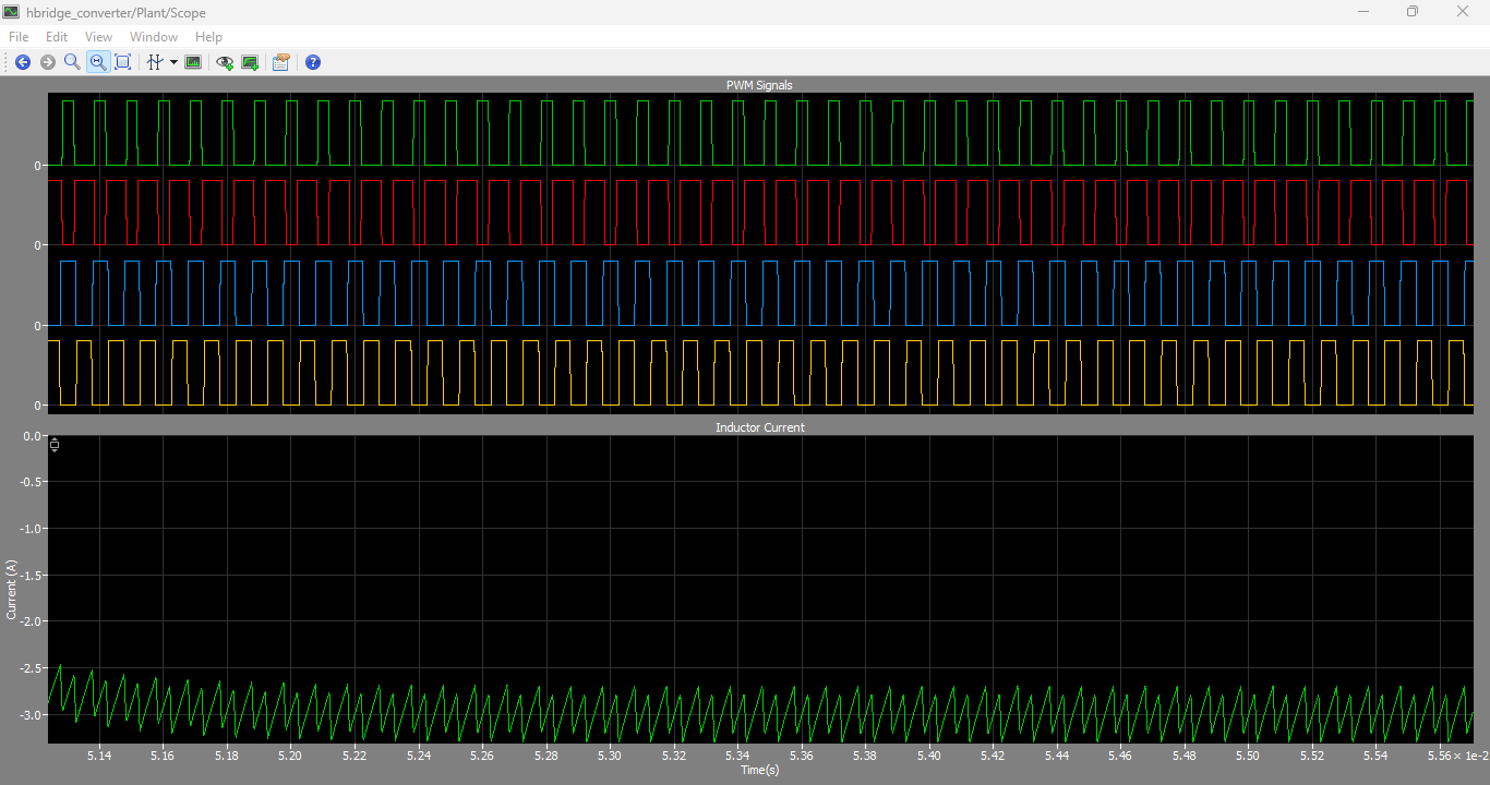
Figure 9: PWM Signals wave forms and Inductor current waveforms
Figure 9 presents the PWM switching signal waveforms and the corresponding inductor current waveforms generated during the real-time simulation of the H-bridge converter in the PLECS environment. The PWM signals illustrate the switching patterns applied to the H-bridge power switches by the controller subsystem. These pulse-width modulated signals are generated according to the duty cycle calculated by the proportional–integral (PI) current controller. The switching pulses operate at a fixed switching frequency and regulate the average output voltage of the converter by varying the pulse widths during each switching cycle.
The figure 9 also shows the inductor current response corresponding to the applied PWM switching actions. The inductor current follows the commanded reference current with smooth transitions and controlled ripple characteristics. During positive and negative current transitions, the PWM signals change polarity to reverse the voltage applied across the RL load, thereby enabling bidirectional current flow through the inductor. The inductive load filters the high-frequency switching components, resulting in a relatively smooth current waveform despite the rapid switching operation of the converter.
Furthermore, the relationship between the PWM pulses and the inductor current waveforms confirms the correct operation of the closed-loop current control system. When the duty cycle increases, the average converter output voltage increases, causing the inductor current to rise. Similarly, a reduction in duty cycle decreases the applied voltage and lowers the inductor current. The figure validates the effectiveness of the PWM generation logic, switching synchronization, and PI current regulation strategy implemented in the H-bridge converter system. The obtained waveforms also demonstrate stable real-time execution and accurate switching behavior of the converter model on the PLECS RT Box platform.
The PWM switching signals generated by the controller maintain proper complementary switching behavior for the H-bridge converter. The converter output voltage alternates polarity according to the current direction, enabling bidirectional current flow through the RL load. The inductor smooths the current waveform and reduces ripple caused by high-frequency switching operation.
The RT Box execution results confirm deterministic real-time performance. The plant subsystem executes within the defined 2 μs discretization interval without violating timing constraints. Processor utilization remains within safe operating limits, even during dynamic current transitions and external mode communication.
The analog scaling circuits accurately emulate practical voltage and current sensing hardware. The measured analog outputs remain within the 0–3.3 V range required for embedded controller ADC inputs. This realistic hardware emulation improves the reliability of hardware-in-the-loop testing and ensures compatibility with external control platforms.
The enable/disable protection logic successfully forces the PWM outputs into a safe state during shutdown conditions. The anti-windup mechanism prevents integrator saturation during abrupt current changes, contributing to improved stability and smooth controller recovery.
Overall, the obtained results demonstrate that the proposed system provides a reliable platform for real-time validation of power electronic converter control strategies. The modular architecture and real-time execution capabilities make the system suitable for educational, research, and industrial applications involving embedded power electronics control.
VII. Conclusion
This paper presented a complete real-time implementation of a current-controlled H-bridge converter using the PLECS RT Box platform. The converter system consists of a full-bridge power stage supplying an inductive RL load under closed-loop PI current control. The system was divided into plant and controller subsystems to support hardware-in-the-loop testing and rapid control prototyping applications.
The mathematical modeling of the RL load and converter dynamics was presented, and the controller parameters were designed using the magnitude optimum criterion. Realistic voltage and current sensing circuits were implemented to emulate practical embedded hardware measurement systems. The converter and controller were successfully executed on separate RT Boxes communicating through analog and digital interfaces.
The experimental and simulation results demonstrated stable current regulation, accurate PWM switching behavior, reliable real-time execution, and effective protection functionality. The proposed implementation confirms the suitability of the PLECS RT Box platform for high-fidelity real-time power electronics simulation and embedded controller validation.
Future work may include implementation of advanced control strategies such as model predictive control, adaptive current regulation, and digital deadbeat control. In addition, extension of the proposed approach to motor drive applications and bidirectional DC–DC converter systems can further enhance the applicability of the developed platform.
References
[1] J. Allmeling and N. Felderer, “Sub cycle average models with integrated diodes for real-time simulation of power converters,” IEEE Southern Power Electronics Conference (SPEC), 2017.
[2] Texas Instruments, “DRV8305N 3-Phase Motor Drive BoosterPack Evaluation Module,” Available: http://www.ti.com/tool/BOOSTXL-DRV8305EVM
[3] H. Bühler, Conception de systèmes automatiques, Presses Polytechniques Romandes, Lausanne, 1988.
You can download the Project files here: Download files now. (You must be logged in).


Responses