

Multistep Model Predictive Control for Three-Level NPC Inverter Driving an Induction Machine
Author: Waqas Javaid
Abstract
This paper presents the design and implementation of a multistep finite control set model predictive control (FCS-MPC) strategy for a medium-voltage three-level neutral-point-clamped (NPC) inverter driving a squirrel-cage induction machine. The complete system has been developed and simulated in PLECS using the RT Box environment for real-time rapid control prototyping and hardware-in-the-loop validation. The proposed controller predicts future stator current trajectories over a prediction horizon of while minimizing switching transitions through an optimized cost function. A modified sphere decoding algorithm is employed to reduce computational burden and improve optimization efficiency. The simulation results demonstrate excellent current tracking capability, reduced switching frequency, and stable dynamic performance under varying operating conditions and load torque disturbances.
I. Introduction
Medium-voltage motor drive systems are widely utilized in industrial applications such as rolling mills, electric propulsion systems, mining equipment, compressors, and renewable energy conversion systems. Among the available converter topologies, the three-level neutral-point-clamped (NPC) inverter has gained considerable attention due to its superior voltage quality, reduced switching stress, and lower harmonic distortion compared to conventional two-level inverters [1].
Traditional control strategies such as vector control and direct torque control require cascaded regulators and pulse-width modulation stages, which increase system complexity and reduce dynamic performance [2]. Finite control set model predictive control (FCS-MPC) has emerged as an attractive alternative because it directly determines the optimal switching state of the inverter using a system model and a cost function [3].
In this work, a multistep predictive controller with a prediction horizon of is implemented for a three-level NPC inverter-fed induction machine drive. The controller predicts future stator currents and minimizes switching transitions using a modified sphere decoding algorithm. The complete model is implemented in PLECS and validated through detailed simulation studies.
II. System Configuration and Modeling
A. Overall System Structure
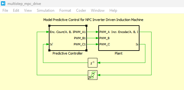
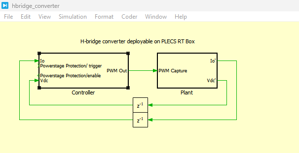
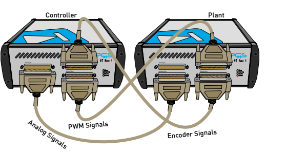
Figure 1 presents the overall structure of the predictive control system. The model consists of two major subsystems: the plant subsystem and the predictive controller subsystem.
Figure 1: Top-level schematic of the predictive controller and plant subsystems.
The plant subsystem contains the three-level NPC inverter, squirrel-cage induction machine, PWM capture modules, encoder interface, and measurement blocks. The controller subsystem includes the rotor flux observer, speed controller, flux controller, predictive current controller, and switching optimization algorithm. The controller communicates with the plant through analog and digital interfaces, enabling real-time operation in the RT Box environment.
B. Three-Level NPC Inverter Model
Figure 2 illustrates the complete power circuit of the three-level neutral-point-clamped (NPC) inverter-fed induction motor drive developed in PLECS. The system consists of a medium-voltage three-phase NPC inverter connected to a squirrel-cage induction machine, where each inverter leg generates three voltage levels (+Vdc/2, 0, −Vdc/2) to improve output waveform quality and reduce harmonic distortion. PWM Capture blocks are used to receive switching signals from the predictive controller, while Analog Out and Incremental Encoder blocks provide current, speed, and position feedback signals for closed-loop operation. The developed model enables accurate real-time simulation of inverter switching behavior, machine dynamics, and predictive control performance within the RT Box environment.
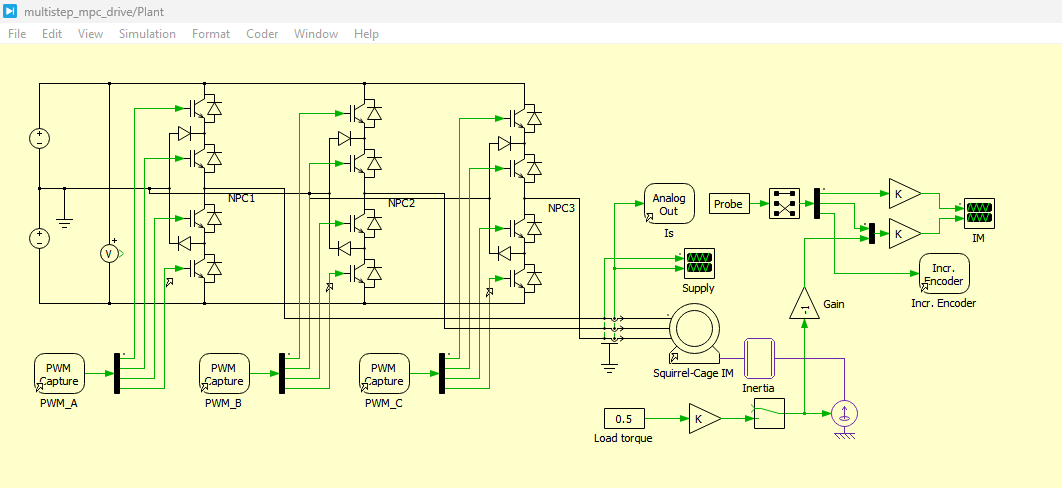
Figure 2: Power circuit of the three-level NPC inverter-fed induction motor drive.
The three-level NPC inverter is composed of three NPC half-bridge legs. Each phase can generate three voltage levels:

where:
- Vdc= DC-link voltage
The use of three voltage levels significantly reduces output voltage harmonics and switching losses. The neutral-point clamping diodes help distribute voltage stress equally among semiconductor devices [1].
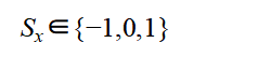
The switching states of the inverter are represented as:
where:
- Sx=1 corresponds to positive DC-link connection
- Sx=0 corresponds to neutral point connection
- Sx=-1 corresponds to negative DC-link connection
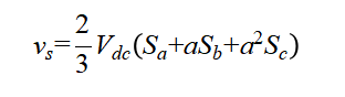
The output voltage vector of the inverter in the stationary reference frame is expressed as [2]:
where:
and:
- Sa, Sb, Sc, are switching states of phases A, B, and C.
This equation forms the basis for predictive current estimation in the MPC controller [2].
C. Induction Machine Mathematical Model
The induction machine is modeled in the stationary reference frame. The stator voltage equations are expressed as [3]:
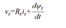
where:
- vs= stator voltage vector
- Rs= stator resistance
- is= stator current vector
- ψs= stator flux linkage vector
The rotor flux linkage is defined as:
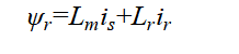
where:
- Lm= mutual inductance
- Lr= rotor inductance
- ir= rotor current vector
The electromagnetic torque is calculated using [4]:
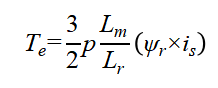
where:
- p= number of pole pairs
The rotor mechanical dynamics are represented by:
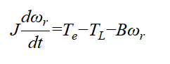
where:
- J= rotor inertia
- ωr= rotor angular speed
- T_L= load torque
- B= friction coefficient
These equations are used for future current prediction in the MPC controller [3], [4].
III. Rotor Flux Estimation
Since rotor flux cannot be directly measured, an observer is implemented using machine equations.
Figure 3 shows the rotor flux observer implemented in the controller subsystem and MPC controller.
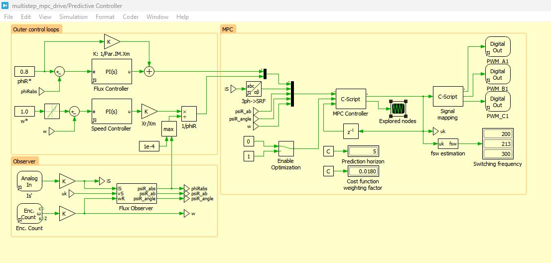
Figure 3: Rotor flux observer, MPC control and outer control loops implemented in PLECS.
You can download the Project files here: Download files now. (You must be logged in).
Figure 3 presents the rotor flux observer, model predictive current controller (MPC), and outer speed and flux control loops implemented in the PLECS environment. The outer control loops generate the reference d-axis and q-axis stator currents based on the rotor speed and flux errors, ensuring stable torque and flux regulation of the induction machine. The rotor flux observer estimates the rotor flux magnitude and angle using measured stator currents, inverter voltages, and rotor speed signals, eliminating the need for direct flux sensors. The MPC controller then predicts future stator current behavior for all possible switching states and selects the optimal inverter switching vector that minimizes the cost function while reducing switching frequency. This integrated control structure provides fast dynamic response, accurate current tracking, and improved drive performance under varying operating conditions.
The rotor flux estimation equation is expressed as [5]:
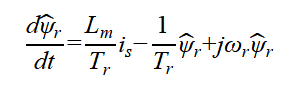
where:
The observer estimates both flux magnitude and angle, which are used by the predictive current controller.
IV. Predictive Current Control Strategy
A. Principle of FCS-MPC
The predictive controller evaluates all possible switching states and predicts future stator currents. The optimal switching vector minimizing the cost function is selected and applied during the next sampling interval.
The predicted stator current is calculated using discrete-time machine equations [6]:
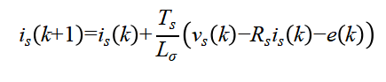
where:
- Ts= sampling time
- Lσ= leakage inductance
- e(k)= back electromotive force
The future current trajectories are evaluated over the prediction horizon.
B. Cost Function Formulation
The controller objective is to minimize current tracking error and switching transitions simultaneously.
The cost function is defined as [2]:
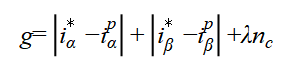
where:
The first two terms minimize current tracking error, while the third term minimizes switching frequency.
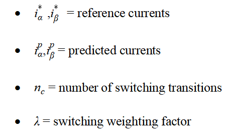
For a multistep horizon, the total cost function becomes [2]:
where:
- Np= prediction horizon
Increasing prediction horizon improves control performance but also increases computational complexity.
C. Modified Sphere Decoding Algorithm
To reduce computational burden, a modified sphere decoding algorithm is implemented.
Figure 4 presents the pseudo-code of the optimization algorithm.
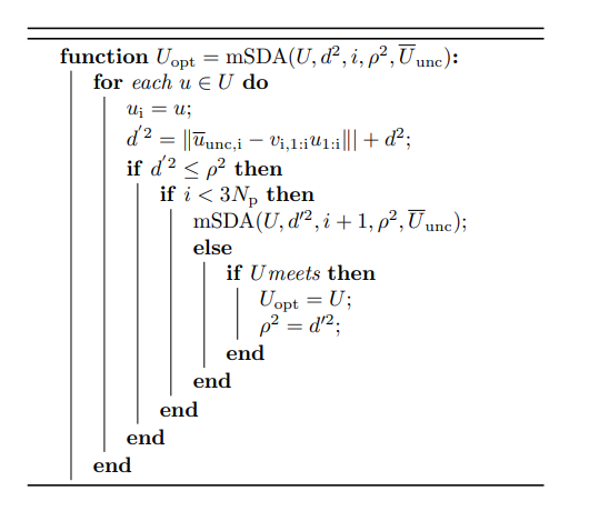
Figure 4: Modified sphere decoding optimization algorithm.
The sphere decoding method searches only feasible switching sequences inside a constrained search region, significantly reducing the number of evaluated nodes compared to exhaustive search [2].
The unconstrained solution vector is initially calculated as:
where:
- Uunc= unconstrained optimal switching vector
The optimization algorithm recursively searches candidate solutions satisfying:
where:
The radius is continuously reduced whenever a better solution is found, allowing the algorithm to converge rapidly toward the optimal switching sequence [2].
V. Outer Flux and Speed Control
Figure 5 shows the speed and flux control loops integrated with the MPC controller.
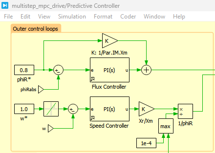
Figure 5: Outer speed and flux control loops.
You can download the Project files here: Download files now. (You must be logged in).
Figure 5 presents the outer speed and rotor flux control loops implemented for the three-level NPC inverter-fed induction motor drive system. The speed control loop compares the reference rotor speed with the measured motor speed and generates the q-axis current reference required for electromagnetic torque production. Simultaneously, the flux control loop regulates the rotor flux magnitude by generating the d-axis current reference to maintain proper machine magnetization. These reference current components are then supplied to the MPC controller, which predicts the optimal switching states of the inverter for accurate current tracking and reduced switching losses. The coordinated operation of the speed, flux, and predictive current controllers ensures stable dynamic response, improved torque regulation, and efficient induction motor operation under varying load conditions.
The speed controller generates the q-axis current reference, while the flux controller generates the d-axis current reference.
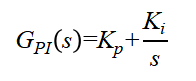
The PI speed controller is represented as:
where:
- Kp= proportional gain
- Ki= integral gain
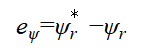
The speed control error is expressed as:
![]()
where:
Similarly, the flux controller regulates rotor flux magnitude according to:
where:
These outer loops provide reference currents to the predictive current controller.
VI. Simulation Setup
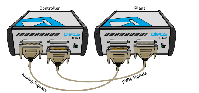
The complete system is developed in PLECS using RT Box rapid control prototyping architecture.
The machine parameters are based on a 2 MVA, 3.3 kV squirrel-cage induction machine.
Table 1: Key system parameters are summarized below:
| Parameter | Value |
| Rated Power | 2 MVA |
| DC-Link Voltage | 5.2 kV |
| Rated Frequency | 50 Hz |
| Prediction Horizon | 5 |
| Switching Frequency | 300 Hz |
| Pole Pairs | 5 |
The plant subsystem is executed on RT Box 1, while the predictive controller runs on RT Box 2/3.
VII. Simulation Results and Discussion
A. Phase Voltage and Current Waveforms
Figure 6 presents the three-level NPC inverter output phase voltages together with the corresponding stator phase currents of the induction motor drive system.
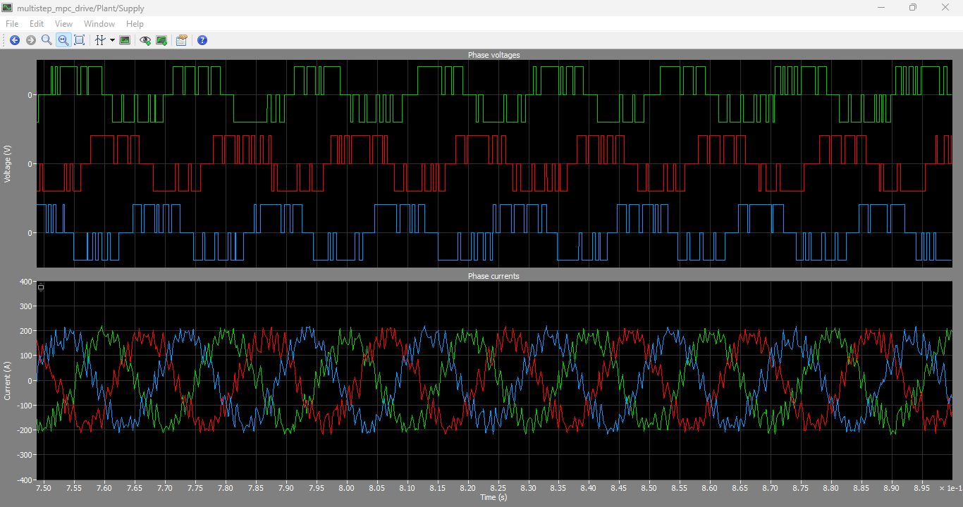
Figure 6: Three-level NPC inverter output phase voltages and phase currents.
Figure 6 presents the output voltages clearly demonstrate the multilevel staircase waveform characteristics produced by the three-level neutral-point-clamped inverter. The inverter successfully generates positive, zero, and negative voltage levels according to the NPC switching states, which significantly reduces voltage harmonics compared to conventional two-level inverters. At the same time, the stator phase currents closely follow sinusoidal reference waveforms with very low ripple and distortion due to the action of the multistep model predictive controller. The balanced voltage and current waveforms confirm accurate switching state selection, stable induction motor operation, and effective current tracking performance. Furthermore, the reduced harmonic distortion and smooth current response validate the effectiveness of the predictive control strategy in improving power quality and overall drive performance.
B. Rotor Speed Response
Figure 7 presents the rotational speed dynamic response of the induction motor drive system under varying load torque conditions. The waveform demonstrates that the proposed multistep model predictive controller maintains stable speed regulation with fast transient response and minimal overshoot during load disturbances. The motor speed quickly tracks the reference value even when sudden load torque variations are applied, indicating effective torque compensation capability of the controller. The smooth dynamic response and rapid stabilization confirm the robustness and high-performance operation of the predictive control strategy for medium-voltage induction motor drives.
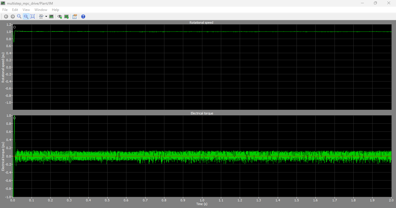
Figure 7: Rotational speed dynamic response under load torque variations output graphs.
The speed response demonstrates excellent transient performance and rapid tracking capability. The controller maintains stable speed regulation even during sudden load torque changes. Minimal overshoot and fast settling time validate the robustness of the predictive control strategy. The dynamic performance confirms effective coordination between the speed controller and predictive current controller.
C. Switching Frequency Optimization
Figure 8 presents the explored switching nodes obtained using the modified sphere decoding optimization algorithm implemented in the multistep model predictive controller. The graph illustrates the reduced number of evaluated switching combinations during each sampling interval, demonstrating the computational efficiency of the optimization technique. Instead of exhaustively evaluating all possible switching states, the modified sphere decoding method intelligently searches only the most promising switching vectors, significantly reducing execution time while still achieving the optimal control solution. The results confirm that the proposed optimization strategy enables fast real-time implementation of long-horizon predictive control for the three-level NPC inverter drive system.
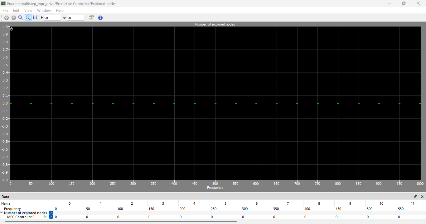
Figure 8: Explored switching nodes using modified sphere decoding optimization.
You can download the Project files here: Download files now. (You must be logged in).
The optimization algorithm evaluates only a small subset of possible switching combinations, substantially reducing computational burden. The sphere decoding approach efficiently eliminates suboptimal branches during recursive search. The reduced explored nodes demonstrate the computational efficiency of the proposed optimization strategy. This enables real-time implementation for long prediction horizons.
E. Effect of Prediction Horizon
Figure 9 compares system performance for different prediction horizons.
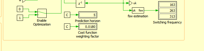
Figure 9: Effect of prediction horizon on current tracking performance.
Increasing the prediction horizon improves current tracking accuracy and dynamic response. However, longer horizons increase computational complexity and optimization effort. A prediction horizon of provides an effective compromise between dynamic performance and computational requirements. The selected horizon achieves stable operation with acceptable execution time for real-time implementation.
VIII. Discussion
The developed multistep FCS-MPC strategy demonstrates significant advantages over conventional vector control techniques. The controller directly manipulates inverter switching states without requiring additional PWM modulators. This simplifies the control structure while improving transient performance.
The modified sphere decoding algorithm successfully addresses the major drawback of predictive control, namely computational complexity. By reducing the number of explored switching combinations, the controller becomes suitable for real-time applications with long prediction horizons.
The three-level NPC topology further improves power quality by reducing voltage harmonics and switching stress. Combined with predictive current control, the system achieves excellent steady-state and dynamic performance.
The simulation results confirm that the proposed controller provides:
- Accurate stator current tracking
- Reduced switching frequency
- Improved voltage waveform quality
- Fast transient response
- Stable operation under load disturbances
- Reduced computational burden
IX. Conclusion
This paper presented a multistep finite control set model predictive control strategy for a three-level NPC inverter-fed induction machine drive developed in PLECS. The controller predicts future stator current trajectories over a finite prediction horizon and selects optimal switching states by minimizing a cost function.
A modified sphere decoding optimization algorithm was implemented to reduce computational burden and enable real-time execution. The simulation results demonstrated excellent current tracking performance, reduced switching frequency, low harmonic distortion, and stable dynamic response.
The developed system is suitable for medium-voltage industrial drive applications requiring fast dynamic response and high-quality power conversion.
References
[1] J. Rodríguez, J. Pontt, C. Silva, et al., “Predictive Current Control of a Voltage Source Inverter,” IEEE Transactions on Industrial Electronics, vol. 54, no. 1, pp. 495–503, 2007.
[2] T. Geyer and D. E. Quevedo, “Multistep Finite Control Set Model Predictive Control for Power Electronics,” IEEE Transactions on Power Electronics, vol. 29, no. 12, pp. 6836–6846, 2014.
[3] P. Cortés, M. Kazmierkowski, R. Kennel, et al., “Predictive Control in Power Electronics and Drives,” IEEE Transactions on Industrial Electronics, vol. 55, no. 12, pp. 4312–4324, 2008.
[4] B. K. Bose, Modern Power Electronics and AC Drives, Prentice Hall, 2002.
[5] R. Krishnan, Electric Motor Drives: Modeling, Analysis and Control, Prentice Hall, 2001.
[6] S. Vazquez, J. Rodríguez, M. Rivera, et al., “Model Predictive Control for Power Converters and Drives,” IEEE Transactions on Industrial Electronics, vol. 59, no. 5, pp. 2346–2358, 2012.
You can download the Project files here: Download files now. (You must be logged in).


Responses