

Direct Torque Control of an Asynchronous Machine Using MATLAB/Simulink
Author: Waqas Javaid
Abstract
Direct Torque Control (DTC) has emerged as one of the most effective high-performance control strategies for induction motor drives due to its fast dynamic response, reduced dependence on machine parameters, and simple implementation structure. This research paper presents the modeling, design, and control implementation of an asynchronous machine using the Direct Torque Control technique in MATLAB/Simulink. The proposed system utilizes a PI-based speed controller for torque reference generation while a DTC switching table and flux estimator generate inverter switching pulses for torque and stator flux regulation. The study focuses on the mathematical modeling of the induction machine, inverter topology, stator flux estimation, hysteresis-based torque and flux control, and the dynamic performance of the drive system under varying operating conditions. The complete control structure is implemented and validated in MATLAB/Simulink using realistic machine parameters. The developed controller demonstrates rapid torque response, minimized steady-state error, improved speed tracking capability, and effective decoupled control of torque and flux. Furthermore, the proposed system offers superior transient characteristics compared to conventional vector control methods while maintaining a relatively simpler control structure. The research also discusses the advantages, limitations, and future developments of DTC strategies for industrial high-power asynchronous machine applications.
I. Introduction
Induction machines, also referred to as asynchronous machines, are widely used in industrial and commercial applications due to their rugged construction, reliability, low maintenance requirements, and cost-effectiveness. Applications such as electric vehicles, conveyor systems, rolling mills, robotics, aerospace systems, and renewable energy systems require high-performance speed and torque control of induction motors. Traditional scalar control techniques such as V/f control provide simple operation; however, they suffer from poor dynamic response and limited accuracy during transient conditions [1].
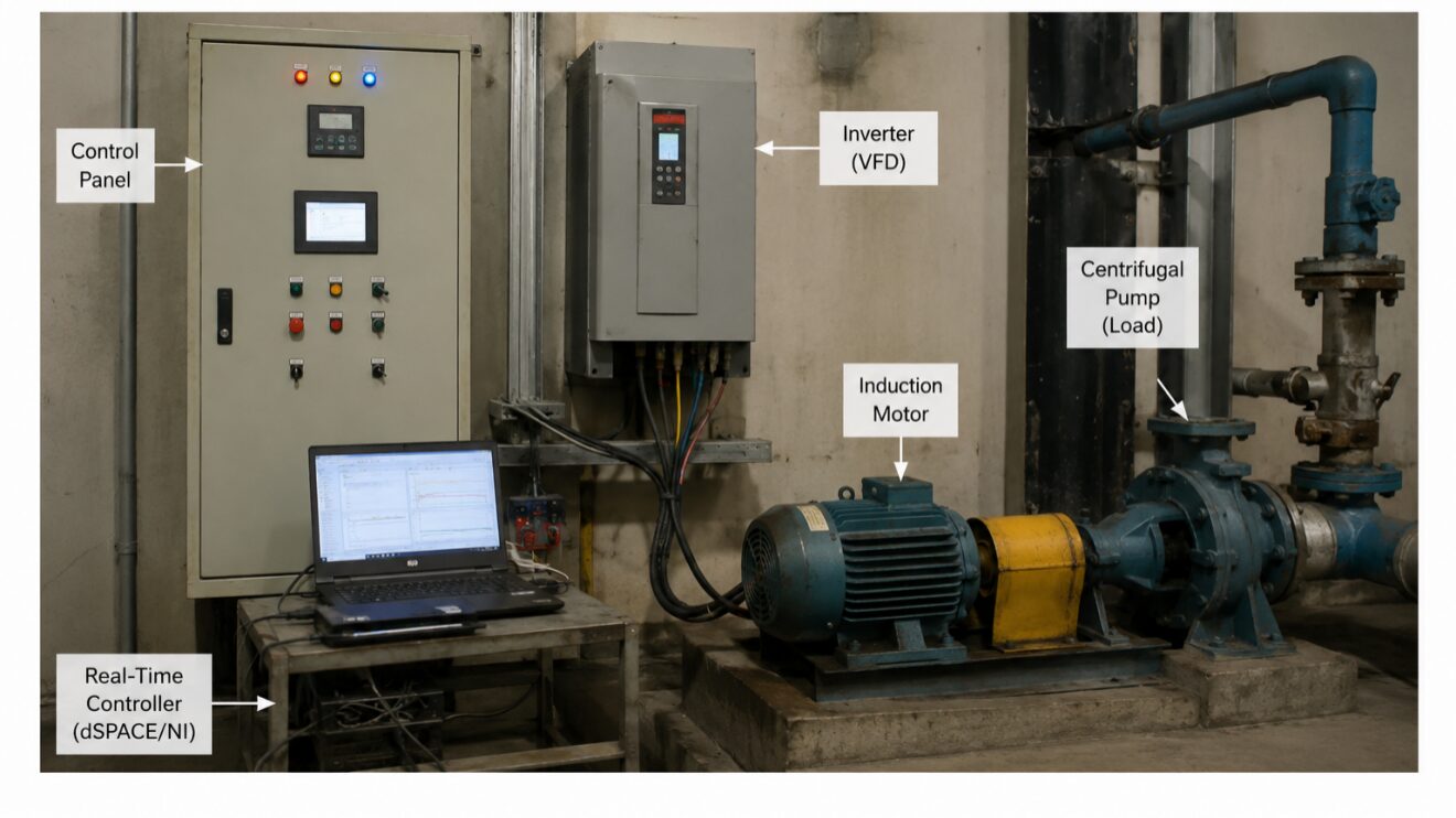
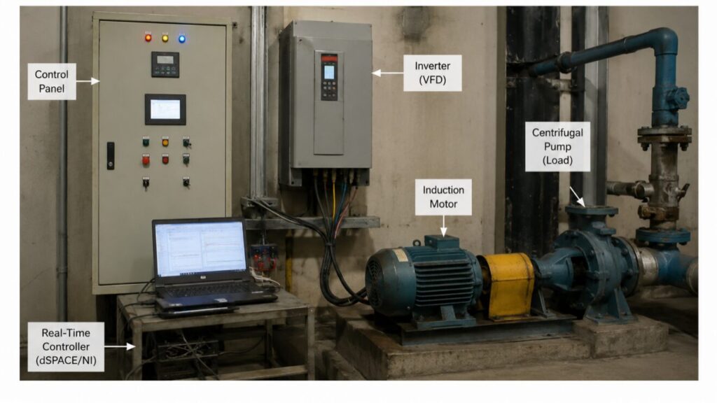
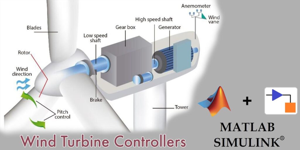
Figure 1: DTC-Based Real-Time Induction Motor Drive System in Industrial Environment
This figure 1 illustrates a real-world industrial setup of a Direct Torque Control (DTC) based induction motor drive system. It shows the integration of a control panel, inverter (VFD), real-time controller, and an induction motor driving a centrifugal pump. The setup represents how DTC is implemented in practical applications to achieve fast torque response, efficient speed control, and robust performance in industrial automation systems such as pumping stations.
To overcome these limitations, advanced control strategies including Field Oriented Control (FOC) and Direct Torque Control (DTC) have been developed. Among these methods, DTC has gained significant attention due to its fast torque response, simple structure, reduced parameter dependency, and elimination of coordinate transformations and current regulators [2]. Since its introduction by Takahashi in the 1980s, DTC has become one of the most preferred control methods for high-performance induction motor drives.
The main principle of DTC is the direct control of stator flux and electromagnetic torque through optimal voltage vector selection using hysteresis comparators and switching tables. Unlike vector control techniques, DTC does not require complex pulse width modulation (PWM) generation or rotor flux orientation calculations. Instead, torque and flux are directly estimated from measured stator voltages and currents, resulting in rapid control action and simplified implementation [3].
Despite its advantages, conventional DTC suffers from several drawbacks such as torque ripple, variable switching frequency, and current distortion at low speeds. Numerous research efforts have focused on improving DTC performance through space vector modulation, predictive control, adaptive control, artificial intelligence-based optimization, and fuzzy logic techniques [4]. However, conventional hysteresis-based DTC remains highly popular in industrial applications because of its simplicity and fast transient response.
This research paper presents the complete design and implementation of an asynchronous machine DTC system using MATLAB/Simulink. The developed model incorporates:
- A detailed induction machine mathematical model.
- A stator flux and electromagnetic torque estimator.
- A hysteresis-based DTC controller.
- A PI-based speed regulator.
- A voltage source inverter (VSI).
- Dynamic performance evaluation under different operating conditions.
The main objective of this work is to investigate the performance characteristics of DTC for a high-power induction machine and evaluate the effectiveness of the developed control strategy using simulation tools.
II. Literature Review
The development of advanced induction motor control techniques has evolved significantly over the past several decades. Early induction motor drives relied mainly on scalar control methods due to their simplicity and ease of implementation. However, scalar control techniques failed to provide accurate torque and speed control during dynamic operating conditions.
Field Oriented Control introduced decoupled control of torque and flux, enabling induction motors to perform similarly to separately excited DC motors [5]. Although FOC improved dynamic performance, it required complex coordinate transformations, parameter estimation, and current regulators.
Direct Torque Control was introduced as an alternative high-performance control strategy with reduced computational complexity. Takahashi and Noguchi proposed the first DTC method for induction motors in 1986 [6]. Their method directly controlled torque and stator flux using hysteresis controllers and switching tables without requiring current regulators or PWM modules.
Depenbrock later introduced the Direct Self Control (DSC) method, which further simplified induction motor control for high-power applications [7]. Since then, extensive research has been conducted to improve DTC performance. Researchers proposed space vector modulation-based DTC to reduce torque ripple and maintain constant switching frequency [8]. Predictive DTC methods were also developed to optimize switching states and improve transient response [9].
Artificial intelligence techniques including neural networks, fuzzy logic, and genetic algorithms have also been integrated with DTC systems to enhance robustness and reduce parameter sensitivity [10]. Adaptive DTC methods have shown improved low-speed performance and better disturbance rejection under varying load conditions.
Despite the development of advanced DTC techniques, conventional hysteresis-based DTC remains highly attractive due to:
- Simpler implementation.
- Fast transient response.
- Reduced computational requirements.
- High robustness.
- Suitability for real-time industrial applications.
MATLAB/Simulink has become one of the most widely used platforms for DTC research because of its comprehensive simulation environment and powerful control system modeling tools. Researchers have successfully implemented DTC systems for induction motors, PMSMs, renewable energy systems, electric vehicles, and industrial automation applications using MATLAB/Simulink.
This research work contributes by developing a complete DTC-based induction machine drive system using practical machine parameters and evaluating its performance characteristics under dynamic conditions.
III. Mathematical Modeling of the Asynchronous Machine
The induction machine mathematical model is essential for understanding the dynamic behavior of the motor and implementing accurate control strategies. The asynchronous machine consists of stator and rotor windings coupled through magnetic flux.
The stator voltage equation in stationary reference frame is expressed as [11]:
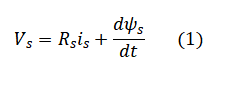
where:
- (V_s) represents stator voltage vector.
- (R_s) is stator resistance.
- (i_s) is stator current vector.
- (ψ_s) is stator flux linkage.
The rotor voltage equation for squirrel-cage induction motors is given by [11]:
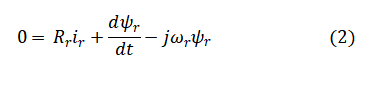
where:
- Rr= Rotor resistance referred to the stator side (Ω)
- i_r= Rotor current vector (A)
- ψr = Rotor flux linkage vector (Wb)
- dψr/dt= Rate of change of rotor flux linkage with respect to time
- ωr= Rotor electrical angular speed (rad/s)
- j = Imaginary operator representing 90° phase shift in complex space-vector notation
The electromagnetic torque produced by the induction machine is expressed as [12]:
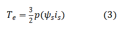
where:
- (T_e) is electromagnetic torque.
- (p) represents pole pairs.
- (ψ_s) is stator flux linkage.
- (i_s) is stator current.
The mechanical dynamics of the machine are represented by [12]:
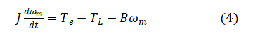
where:
- (J) is rotor inertia.
- (ω_m) is mechanical speed.
- (T_e) is electromagnetic torque.
- (T_L) is load torque.
- (B) is friction coefficient.
The developed model uses per-unit machine parameters converted into actual electrical quantities using base values. The machine parameters used in the simulation correspond to a 164 kW asynchronous machine operating at 550 V and 60 Hz.
IV. Direct Torque Control Principle
Direct Torque Control directly regulates the electromagnetic torque and stator flux by selecting appropriate inverter switching states. The core components of the DTC system include:
- Flux estimator.
- Torque estimator.
- Hysteresis comparators.
- Switching table.
- Voltage source inverter.
A. Stator Flux Estimation
The stator flux is estimated using measured stator voltages and currents. The stator flux components are calculated through integration of stator voltage equations. Accurate flux estimation is essential for maintaining stable machine operation and precise torque control.
The stator flux vector is represented in the stationary (-) reference frame. The magnitude and angle of the flux vector are used for sector determination and voltage vector selection.
B. Electromagnetic Torque Estimation
The electromagnetic torque is estimated using stator flux and current components. Torque estimation enables the DTC controller to compare actual torque with reference torque and generate switching commands accordingly.
C. Hysteresis Controllers
Hysteresis comparators are used to maintain torque and flux within predefined bands. The flux hysteresis controller is typically two-level, while the torque hysteresis controller is generally three-level.
The hysteresis controllers generate digital outputs based on the errors between reference and estimated values.
D. Switching Table
The switching table selects appropriate inverter voltage vectors based on:
- Flux error.
- Torque error.
- Stator flux sector.
The selected voltage vector either increases or decreases stator flux and torque to maintain desired operating conditions.
E. Voltage Source Inverter
The voltage source inverter converts DC power into controlled AC voltages supplied to the induction motor. The inverter switching states are directly generated by the DTC switching table.
V. System Parameters and Design
The asynchronous machine used in this research has the following rated parameters:
Table 1: System Parameters used in the design of Direct Torque Control
| Parameter | Value |
| Rated Power | 164 kW |
| Rated Voltage | 550 V |
| Rated Frequency | 60 Hz |
| Pole Pairs | 2 |
| Stator Resistance | 0.0139 pu |
| Rotor Resistance | 0.0112 pu |
| Magnetizing Inductance | 2.717 pu |
| Moment of Inertia | 0.2734 s |
| Friction Coefficient | 0.0106 pu |
The base values used for per-unit conversion include:
- Base voltage.
- Base current.
- Base impedance.
- Base torque.
- Base electrical angular frequency.
The developed control system utilizes:
- Fundamental sampling time: 5 µs.
- Switching frequency: 2 kHz.
- Control sampling time: 50 µs.
The PI speed controller gains were selected as:
- Proportional gain ((K_p)): 65.47.
- Integral gain ((K_i)): 3134.24.
These parameters were optimized to ensure stable operation, fast speed tracking, and minimal steady-state error.
VI. MATLAB/Simulink Implementation
MATLAB/Simulink provides an effective environment for modeling and analyzing advanced motor control systems. The proposed DTC-based asynchronous machine drive was implemented using Simulink blocks and power electronics libraries.
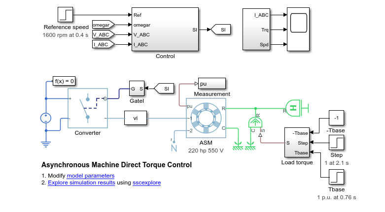
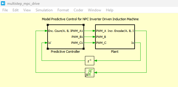
Figure 2: Asynchronous Machine Direct Torque Control Model developed in Simulink
The figure 2 illustrates the complete Asynchronous Machine Direct Torque Control (DTC) model developed in MATLAB/Simulink. It includes the induction motor, inverter, flux estimator, torque controller, and feedback control loops used for high-performance motor operation.
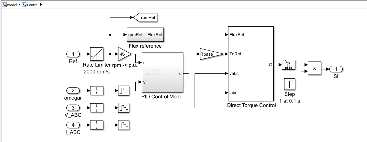
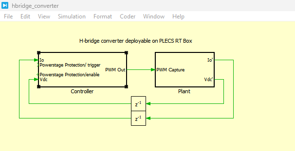
Figure 3: Direct Torque Control with PID control model
You can download the Project files here: Download files now. (You must be logged in).
This figure 3 presents the Direct Torque Control system integrated with a PID controller for improved speed and torque regulation. The PID controller enhances system stability and minimizes steady-state error during transient conditions.
The complete system consists of:
- Asynchronous machine model.
- Voltage source inverter.
- DTC controller.
- Flux estimator.
- Torque estimator.
- PIDspeed controller.
- Reference speed generator.
- Load torque subsystem.
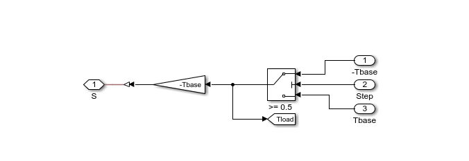
Figure 4: Load Torque control model
This figure 4 demonstrates the load torque control model used to apply varying mechanical loads to the induction motor. The subsystem helps evaluate the robustness and dynamic response of the DTC drive under changing load conditions.
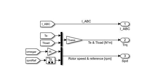
Figure 5: Rotor’s Torque and Speed control system
The figure 5 illustrates the rotor torque and speed control mechanism of the asynchronous machine. It highlights the relationship between electromagnetic torque generation and rotor speed regulation within the DTC framework.
A. Asynchronous Machine Modeling
The induction machine model was implemented using machine equations in the stationary reference frame. The machine parameters were defined according to the provided per-unit values.
B. DTC Controller Implementation
The DTC controller subsystem includes:
- Flux estimation block.
- Torque estimation block.
- Sector identification logic.
- Hysteresis comparators.
- Switching table.
The stator flux vector angle is divided into six sectors for voltage vector selection.
C. PID Speed Controller
The PID speed controller generates the reference electromagnetic torque based on speed error. The controller improves steady-state performance and ensures accurate speed tracking.
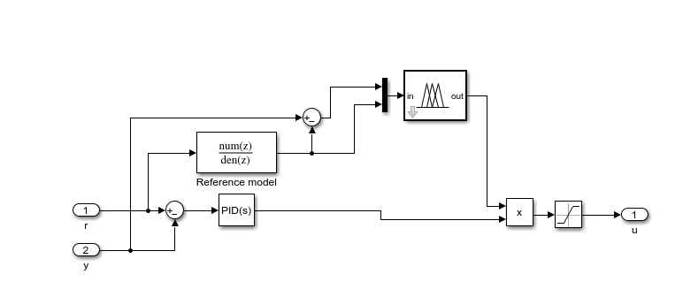
Figure 6: PID control system for the stablize the system
The figure 6 shows the PID control subsystem designed to stabilize the asynchronous machine drive system. It continuously adjusts the control signal based on the error between reference and actual motor speed.
D. Inverter Modeling
The voltage source inverter was modeled using six IGBT switching devices controlled by DTC-generated switching signals.
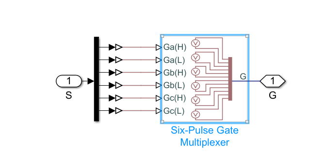
Figure 7: Six Pulse Gate Multiplexer which generates the gate pulses
This figure 7 presents the six-pulse gate multiplexer responsible for generating inverter gate pulses. The generated switching signals control the inverter switches to regulate motor voltage and torque.
E. Simulation Configuration
The simulation was executed using a fixed-step solver with high sampling accuracy to capture switching dynamics and transient responses.
VII. MATLAB Simulation Results and Discussion
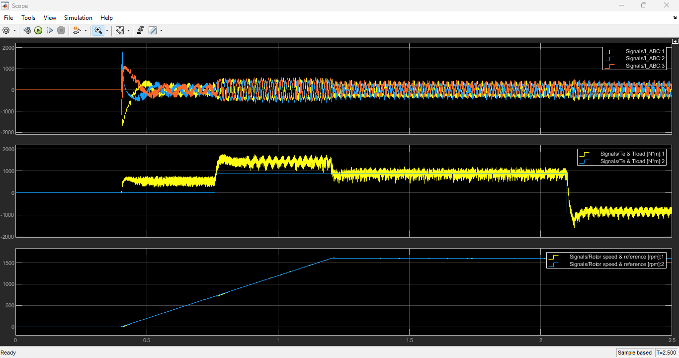
Figure 8: Output Currents, Torques and rotors speed
The figure 8 shows the output current waveforms, electromagnetic torque response, and rotor speed characteristics of the DTC system. These results demonstrate the dynamic performance and stability of the proposed control strategy.
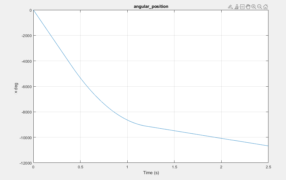
Figure 9: Rotor Angular position
This figure 9 illustrates the rotor angular position variation with respect to time during motor operation. The graph helps analyze the rotational movement and position tracking performance of the induction motor.
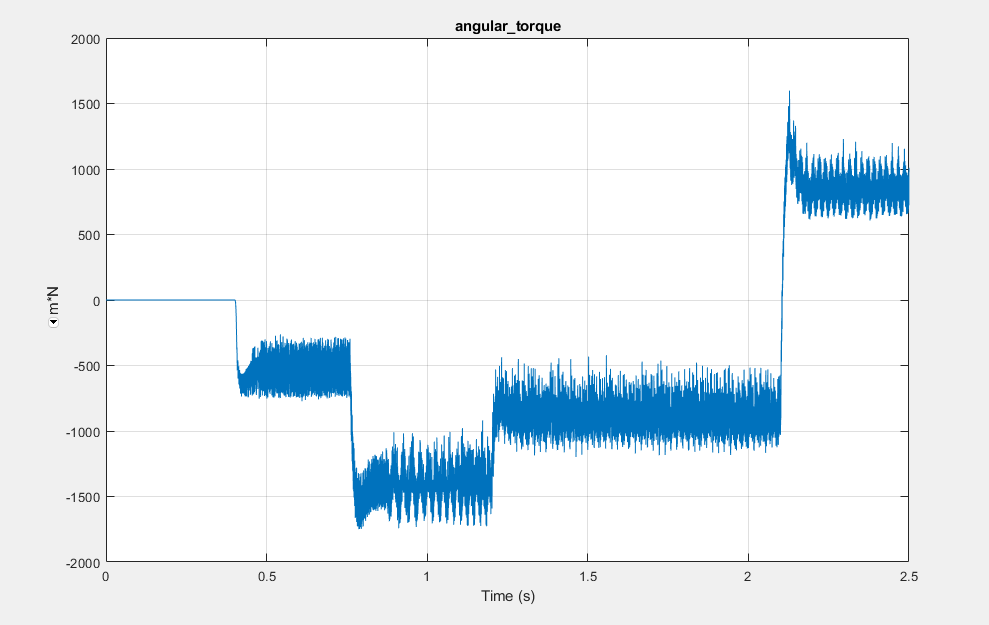
Figure 10: Angular Torque output graph
You can download the Project files here: Download files now. (You must be logged in).
The figure 10 presents the angular torque output response of the DTC-based asynchronous machine drive. It demonstrates the capability of the controller to produce rapid and stable torque under varying operating conditions.
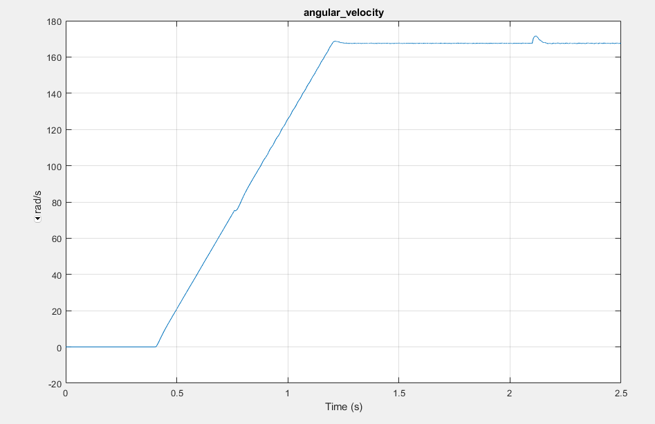
Figure 11: Angular velocity of DTC Model
This figure 11 shows the angular velocity response of the DTC model during simulation. The results indicate effective speed tracking and stable motor performance under dynamic conditions.
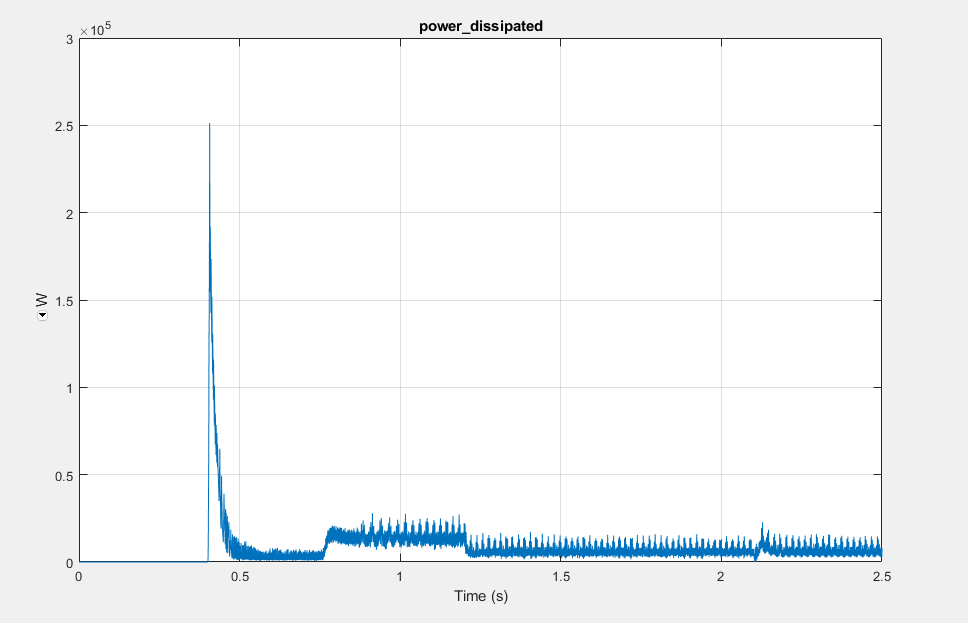
Figure 12: Dissipated power of DTC model
The figure 12 illustrates the dissipated power characteristics of the DTC model during operation. It provides insight into system losses, energy utilization, and overall drive efficiency.
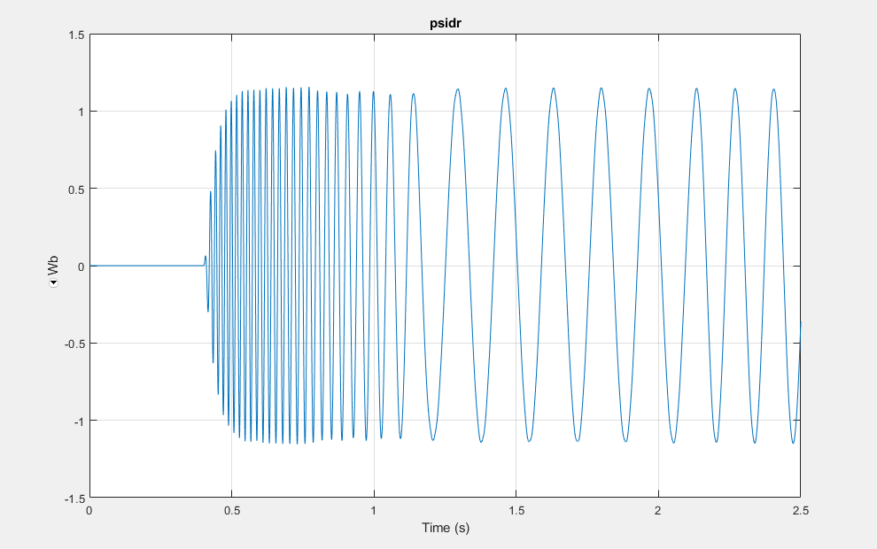
Figure 13: Rotor d-axis magnetic flux linkage
This figure 13 presents the rotor d-axis magnetic flux linkage generated within the induction machine. The flux linkage behavior is essential for analyzing electromagnetic performance and torque production.
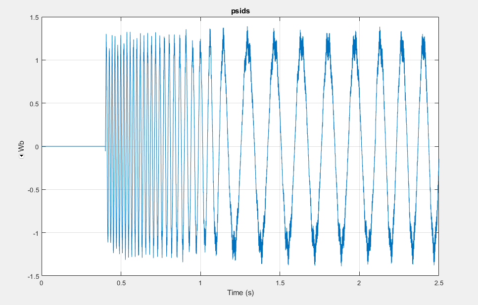
Figure 14: Stator d-axis magnetic flux linkage
The figure 14 shows the stator d-axis magnetic flux linkage of the asynchronous machine. It demonstrates the effectiveness of the DTC strategy in maintaining proper stator flux regulation.
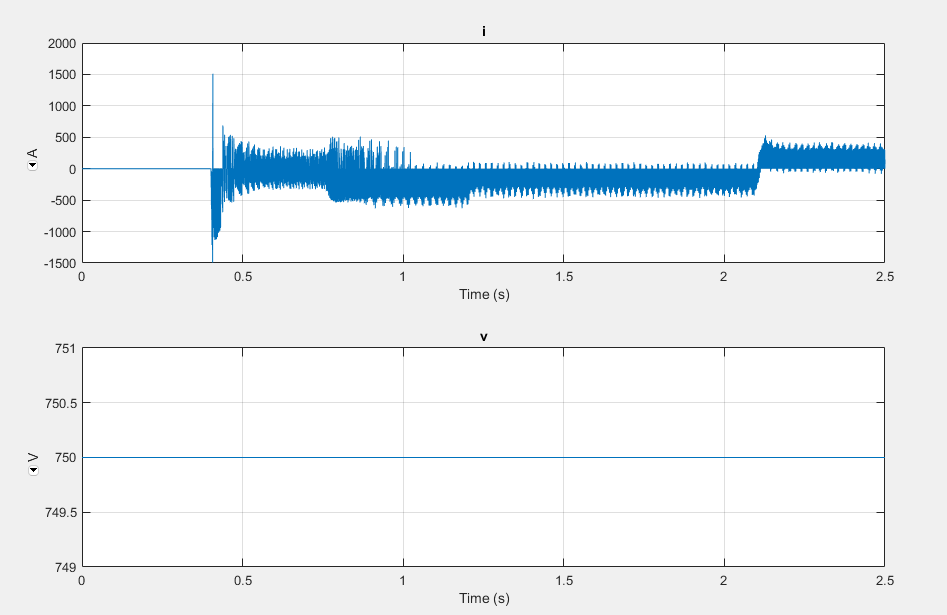
Figure 15: DC Source Current and Voltage
You can download the Project files here: Download files now. (You must be logged in).
This figure 15 illustrates the DC source current and voltage supplied to the inverter system. The waveform analysis helps evaluate DC-link stability and power conversion performance of the drive system.
Table 2: Advantages of Direct Torque Control
| Aspect | Description |
| Fast Dynamic Response | DTC provides extremely fast torque and flux response due to direct inverter voltage vector selection. |
| Simplified Control Structure | DTC eliminates coordinate transformations, PWM generation, and current regulators, resulting in a simpler implementation. |
| Reduced Parameter Sensitivity | The control method is less sensitive to machine parameter variations compared to Field-Oriented Control (FOC). |
| High Efficiency | Efficient utilization of inverter switching states enables rapid energy conversion and improved system performance. |
| Robustness | The controller maintains stable operation under varying load conditions and disturbances. |
Table 3: Limitations of Conventional DTC
| Aspect | Description / Issue |
| Torque Ripple | Hysteresis-based switching introduces noticeable torque ripple in steady-state operation. |
| Variable Switching Frequency | Switching frequency is not constant and varies with operating conditions. |
| Current Distortion | Output current contains higher harmonic distortion compared to PWM-based methods. |
| Low-Speed Performance | Flux estimation becomes less accurate at low speed due to stator resistance effects. |
| Advanced Method Requirement | Limitations motivate improved techniques such as SVM-DTC, predictive DTC, fuzzy logic DTC, neural network DTC, and adaptive DTC. |
X. Future Scope
Future improvements to the proposed system may include:
- Integration of space vector modulation for reduced torque ripple.
- Adaptive parameter estimation techniques.
- Artificial intelligence-based optimization.
- FPGA or DSP-based real-time implementation.
- Electric vehicle drive applications.
- Renewable energy integration.
- Sensorless speed estimation techniques.
- Model predictive direct torque control.
The application of advanced control algorithms can significantly improve the performance and efficiency of industrial asynchronous machine drives.
XI. Conclusion
This research paper presented the design and implementation of a Direct Torque Control system for an asynchronous machine using MATLAB/Simulink. The developed system utilized a PI-based speed controller, stator flux estimator, electromagnetic torque estimator, hysteresis comparators, and a voltage source inverter for high-performance induction motor control.
The mathematical modeling of the asynchronous machine and DTC strategy was discussed in detail. The MATLAB/Simulink implementation demonstrated the feasibility of the proposed control structure for industrial motor drive applications.
The DTC method provided:
- Fast torque response.
- Accurate speed tracking.
- Effective flux regulation.
- Simplified implementation.
- Robust dynamic performance.
Although conventional DTC exhibits torque ripple and variable switching frequency, its advantages in terms of simplicity and dynamic performance make it highly suitable for high-power industrial applications.
Future work may focus on advanced DTC strategies incorporating predictive control, artificial intelligence, and space vector modulation techniques to further improve system performance.
References
[1] B. K. Bose, Modern Power Electronics and AC Drives, Upper Saddle River, NJ, USA: Prentice Hall, 2002.
[2] I. Takahashi and T. Noguchi, “A new quick-response and high-efficiency control strategy of an induction motor,” IEEE Transactions on Industry Applications, vol. IA-22, no. 5, pp. 820–827, Sept. 1986.
[3] M. P. Kazmierkowski and A. B. Kasprowicz, “Improved direct torque and flux vector control of PWM inverter-fed induction motor drives,” IEEE Transactions on Industrial Electronics, vol. 42, no. 4, pp. 344–350, Aug. 1995.
[4] J. Holtz, “Sensorless control of induction motor drives,” Proceedings of the IEEE, vol. 90, no. 8, pp. 1359–1394, Aug. 2002.
[5] F. Blaschke, “The principle of field orientation as applied to the new transvector closed-loop control system for rotating field machines,” Siemens Review, vol. 34, no. 3, pp. 217–220, 1972.
[6] I. Takahashi, “Direct torque control,” Proceedings of the IEEE, vol. 76, no. 10, pp. 1088–1094, Oct. 1988.
[7] M. Depenbrock, “Direct self-control of inverter-fed induction machine,” IEEE Transactions on Power Electronics, vol. 3, no. 4, pp. 420–429, Oct. 1988.
[8] D. Casadei, F. Profumo, G. Serra, and A. Tani, “FOC and DTC: two viable schemes for induction motors torque control,” IEEE Transactions on Power Electronics, vol. 17, no. 5, pp. 779–787, Sept. 2002.
[9] J. Rodriguez and P. Cortes, Predictive Control of Power Converters and Electrical Drives, Hoboken, NJ, USA: Wiley-IEEE Press, 2012.
[10] C. Lascu, I. Boldea, and F. Blaabjerg, “A modified direct torque control for induction motor sensorless drive,” IEEE Transactions on Industry Applications, vol. 36, no. 1, pp. 122–130, Jan. 2000.
[11] P. Vas, Sensorless Vector and Direct Torque Control, Oxford, U.K.: Oxford University Press, 1998.
[12] R. Krishnan, Electric Motor Drives: Modeling, Analysis and Control, Upper Saddle River, NJ, USA: Prentice Hall, 2001.
[13] S. K. Sul, Control of Electric Machine Drive Systems, Hoboken, NJ, USA: Wiley-IEEE Press, 2011.
[14] H. Abu-Rub, A. Iqbal, and J. Guzinski, High Performance Control of AC Drives with MATLAB/Simulink Models, Hoboken, NJ, USA: Wiley, 2012.
[15] M. H. Rashid, Power Electronics: Circuits, Devices and Applications, 4th ed., Upper Saddle River, NJ, USA: Pearson, 2014.
You can download the Project files here: Download files now. (You must be logged in).


Responses