

Design and Real-Time Implementation of a Grid-Connected Single-Phase Inverter Using PLECS RT Box for Hardware-in-the-Loop Applications
Author: Waqas Javaid
Abstract
This paper presents the modeling, control, simulation, and real-time implementation of a grid-connected single-phase inverter developed using the PLECS simulation platform and RT Box real-time hardware. The proposed system is designed for photovoltaic and distributed energy applications requiring efficient AC power injection into the utility grid with stable synchronization and low harmonic distortion. The inverter topology consists of a single-phase H-bridge converter connected to the utility grid through a filter inductor. A closed-loop current control strategy based on a proportional-integral (PI) regulator and a Phase Locked Loop (PLL) is implemented to maintain synchronization between the inverter output current and the grid voltage. The developed controller regulates the injected current at unity power factor while maintaining stable operation under varying operating conditions. The plant and controller models are implemented as separate subsystems to support Hardware-in-the-Loop (HIL) and rapid control prototyping (RCP) applications using dual RT Boxes. Detailed simulation and real-time results demonstrate accurate grid synchronization, stable current tracking, and reliable inverter operation. The proposed model provides an effective platform for advanced grid-connected inverter research and real-time validation.
I. Introduction
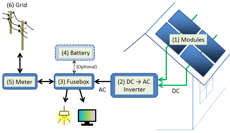
The increasing penetration of renewable energy systems into modern electrical power networks has significantly increased the demand for efficient and reliable grid-connected power electronic converters. Among renewable technologies, photovoltaic systems have become one of the most rapidly expanding energy sources due to their clean operation, low maintenance requirements, and environmental benefits [1]. However, photovoltaic panels inherently generate direct current (DC) power, which must be converted into alternating current (AC) power before injection into the utility grid. This conversion process is performed using grid-connected inverter systems.
Single-phase grid-connected inverters are widely used in residential photovoltaic systems, low-power distributed generation systems, uninterruptible power supplies, and energy storage applications. The major objectives of these inverter systems include maintaining sinusoidal output currents, minimizing harmonic distortion, achieving high conversion efficiency, and ensuring proper synchronization with the utility grid [2].
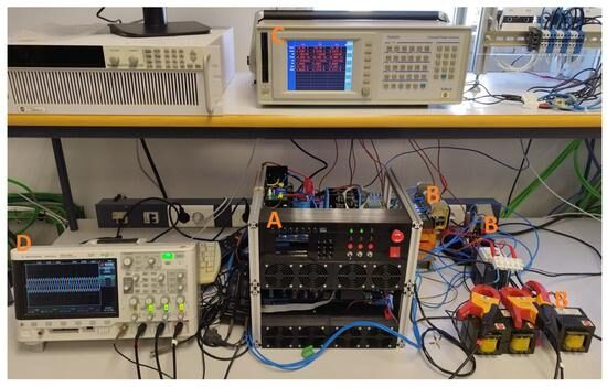
Figure A: Real-Time Hardware-in-the-Loop Implementation of Grid-Connected Inverter System Using PLECS RT Box
The figure A illustrates a real-time experimental and Hardware-in-the-Loop (HIL) implementation setup of the grid-connected inverter system developed using the PLECS RT Box platform. The setup includes the inverter power stage, controller interface, RT Box real-time simulator, measurement instruments, and grid interfacing components used for validation of the proposed control strategy. The experimental arrangement demonstrates practical implementation of grid synchronization, PWM switching control, current regulation, and real-time signal monitoring for renewable energy conversion applications. The presented setup highlights the practical feasibility of the developed inverter system for real-time power electronics and smart grid research applications.
The development of advanced digital control systems and real-time simulation platforms has enabled the implementation of sophisticated inverter control algorithms with improved performance and reliability. Real-time simulation platforms such as PLECS RT Box allow researchers and engineers to perform Hardware-in-the-Loop (HIL) testing and rapid control prototyping before implementing the control system on actual hardware. Such approaches significantly reduce development cost, improve safety, and accelerate controller validation [3].
Grid-connected inverter systems require accurate synchronization with the utility grid in order to maintain stable operation and proper active power transfer. Phase Locked Loop (PLL) algorithms are commonly employed to estimate the grid voltage phase angle and frequency [4]. In addition, closed-loop current controllers based on proportional-integral (PI) regulators are widely used to regulate inverter output current and maintain unity power factor operation.
In this paper, a complete single-phase grid-connected inverter model is developed using PLECS and validated using RT Box real-time hardware. The proposed system includes an H-bridge inverter topology, filter inductor, PLL synchronization unit, PI current controller, and PWM switching strategy. The plant and controller models are implemented separately to support real-time HIL operation.
The main contributions of this paper are summarized as follows:
- Development of a detailed single-phase grid-connected inverter model in PLECS.
- Implementation of a PLL-based synchronization system.
- Design of a closed-loop PI current controller for unity power factor operation.
- Real-time Hardware-in-the-Loop implementation using RT Box.
- Validation of inverter performance using simulation and experimental results.
II. System Architecture and Modeling
A. Overall System Configuration
The developed inverter system consists of the following major components:
- DC voltage source
- Single-phase H-bridge inverter
- Filter inductor
- Utility grid model
- PLL synchronization system
- PI current controller
- PWM generation block
- RT Box interface blocks
The complete system is divided into two independent subsystems:
- Plant subsystem
- Controller subsystem
This separation enables independent deployment of the plant and controller models onto separate RT Boxes for Hardware-in-the-Loop applications.

Figure 1: Performance overview for execution of the plant and controller models on two RT Boxes.
Figure 1 illustrates the execution performance of the developed inverter model on dual RT Box hardware platforms. The figure shows the discretization step sizes and processor utilization for both the plant and controller subsystems. The plant model operates with a smaller simulation step size due to the high-frequency switching behavior of the power electronic converter, while the controller subsystem operates with a comparatively larger step size. The separation of the computational tasks between two RT Boxes significantly reduces processor loading and improves real-time simulation performance. The execution time analysis confirms that the developed model satisfies real-time execution requirements for Hardware-in-the-Loop applications.
III. Top-Level System Modeling
The top-level simulation structure contains two distinct subsystems representing the controller and plant sections of the inverter system. The controller subsystem generates PWM switching signals based on the measured grid voltage and current signals, while the plant subsystem represents the physical power converter and utility grid interface.
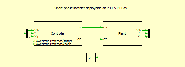
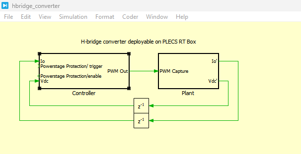
Figure 2: Top-level schematic of the controller and plant model developed in PLECS.
Figure 2 presents the top-level architecture of the developed PLECS simulation model. The model includes separate controller and plant subsystems connected through analog and digital interface blocks. The controller subsystem receives measured signals such as grid voltage, inverter current, and DC-link voltage from the plant model and generates switching pulses for the inverter switches. Delay blocks are included in the feedback path to emulate real-time computational delays. The modular structure of the model improves implementation flexibility and allows independent execution of the plant and controller on separate RT Box hardware platforms.
IV. Power Circuit Design
A. H-Bridge Inverter Topology
The developed power converter utilizes a single-phase H-bridge inverter topology consisting of four insulated gate bipolar transistors (IGBTs). The inverter converts DC power from the photovoltaic source into AC power suitable for utility grid injection.
The DC input voltage is given by:
![]()
where:
- Vdc= DC-link voltage supplied to the inverter
The utility grid voltage is modeled as:
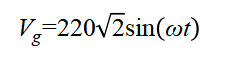
where:
- Vg= grid voltage
- ω= grid angular frequency
- t= time
Equation (2) represents the sinusoidal utility grid voltage operating at 50 Hz [1].
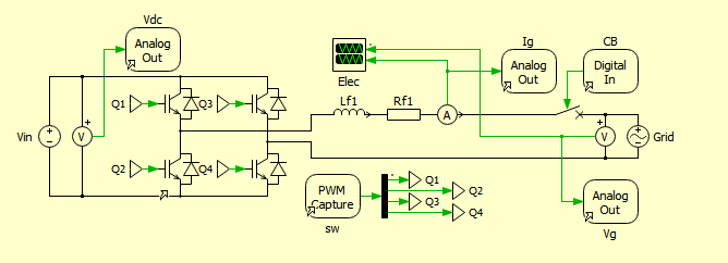
Figure 3: Power circuit of the single-phase grid-connected inverter.
You can download the Project files here: Download files now. (You must be logged in).
Figure 3 presents the detailed power circuit of the developed single-phase grid-connected inverter. The inverter consists of an H-bridge topology formed using four IGBT switches controlled through PWM signals. The inverter output is connected to the utility grid through a filter inductor and resistance which suppress high-frequency switching harmonics before current injection into the grid. Analog output blocks are used to transfer measured signals such as grid voltage, grid current, and DC-link voltage to the controller subsystem. The PWM Capture blocks sample the switching signals with high temporal resolution, enabling accurate real-time simulation of the inverter switching dynamics.
V. Control System Design
A. Phase Locked Loop (PLL)
Grid synchronization is achieved using a single-phase Phase Locked Loop (PLL). The PLL estimates the grid phase angle and angular frequency for synchronization purposes.
The grid angular frequency is defined as:

Frequency slider f updates angular frequency using omega equals two pi times f.
Frequency and angular frequency are linked by omega equals two pi times f. Increasing f makes more cycles appear in the same one second wave window. Current period is 0.667 seconds and the current one second window contains 1.5 cycles.
where:
- ω= angular frequency (rad/s)
- f= grid frequency (Hz)
The PLL continuously tracks the utility grid phase angle to ensure synchronization between the inverter current and the grid voltage.
B. Current Reference Generation
The reference current signal is generated using the PLL output:
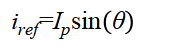
where:
- i_ref= reference grid current
- Ip= reference current amplitude
- θ= grid phase angle obtained from PLL
This equation ensures that the inverter current remains synchronized with the utility grid voltage [4].
C. PI Current Controller
The current error signal is defined as:
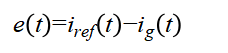
where:
- e(t)= current error
- i_g(t)= measured grid current
The PI controller output is expressed as:
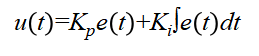
where:
- u(t)= controller output
- Kp= proportional gain
- Ki= integral gain
The PI controller regulates the inverter output current and minimizes steady-state error.
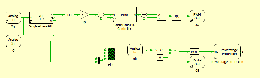
Figure 4: Controller model of the single-phase grid-connected inverter.
Figure 4 illustrates the control architecture of the developed inverter system. The controller subsystem receives measured grid voltage and current signals through Analog In blocks. A PLL block estimates the grid phase angle and frequency, which are used to generate the sinusoidal current reference. The error between the reference current and measured current is processed through a PI regulator to generate the modulation signal for PWM generation. The feedforward grid voltage compensation improves transient response and current tracking accuracy. Furthermore, the controller includes protection logic and anti-windup compensation to ensure stable operation during transient conditions and fault scenarios.
VI. Hardware-in-the-Loop Implementation
The developed inverter model is implemented using dual RT Boxes for real-time operation. One RT Box executes the plant subsystem, while the second RT Box executes the controller subsystem.
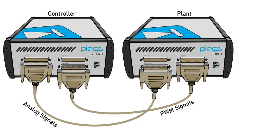
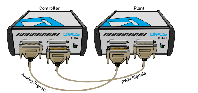
Figure 5: Hardware configuration for real-time operation of the inverter model using dual RT Boxes.
You can download the Project files here: Download files now. (You must be logged in).
Figure 5 presents the Hardware-in-the-Loop configuration employed for real-time implementation of the inverter model. The analog outputs of the plant RT Box are connected to the analog inputs of the controller RT Box, while the digital PWM outputs from the controller are connected to the digital inputs of the plant subsystem. This front-to-front configuration enables closed-loop interaction between the controller and power stage in real time. The modular hardware setup facilitates rapid control prototyping and future expansion toward experimental hardware validation.
VII. Simulation and Experimental Results
The proposed inverter model was simulated and validated using the PLECS simulation environment and RT Box hardware platform. The primary objectives of the simulation study were to evaluate grid synchronization, current tracking accuracy, controller stability, and real-time execution performance.
The inverter was operated at unity power factor while delivering active power to the utility grid. The PLL continuously synchronized the inverter current reference with the utility grid voltage. The PI controller successfully regulated the inverter current under varying operating conditions.
The simulation results demonstrate that the inverter current closely follows the sinusoidal reference current with minimal steady-state error. The inverter output current remains synchronized with the utility grid voltage, confirming successful active power injection into the grid.
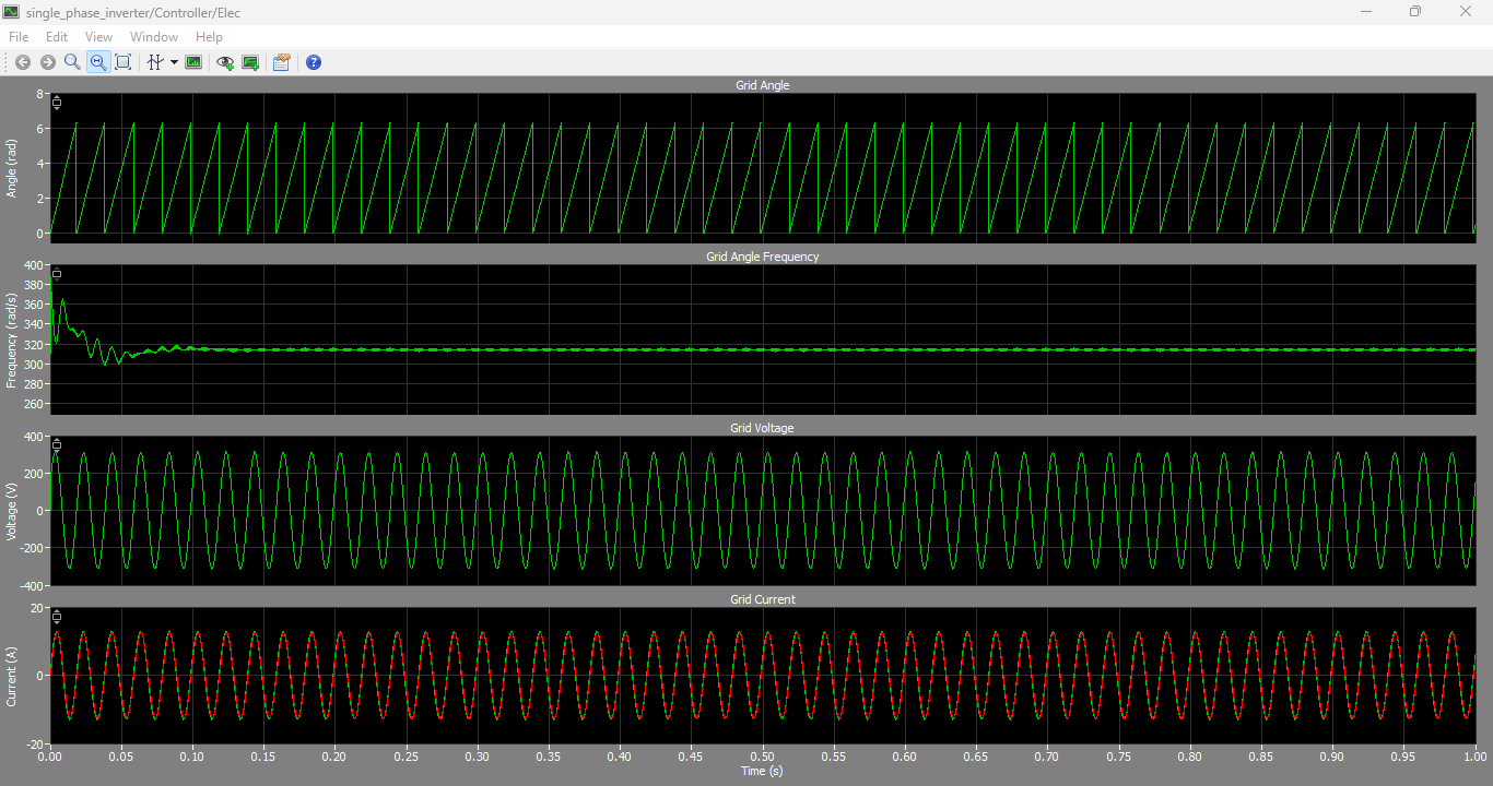
Figure 6: Real-time measurements and intermediate controller signals obtained from the RT Box controller subsystem.
Figure 6 illustrates the measured waveforms and intermediate control signals obtained during real-time operation of the inverter system. The upper waveform represents the detected grid phase angle generated by the PLL algorithm. The second waveform shows the estimated grid angular frequency, which remains stable around the nominal operating frequency. The third waveform represents the measured utility grid voltage, while the fourth waveform illustrates the measured inverter output current injected into the grid.
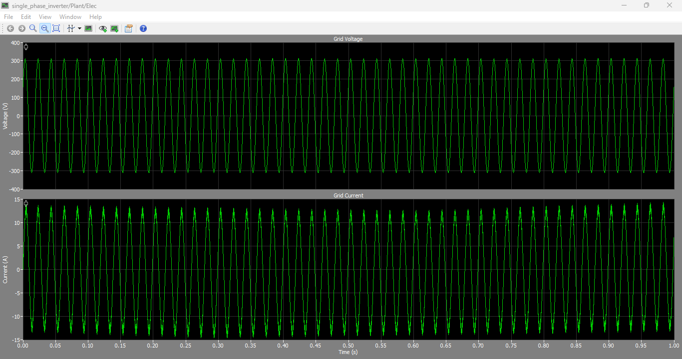
Figure 7: Grid Voltage and Grid Current Output graphs generated in PLECS Simulation
You can download the Project files here: Download files now. (You must be logged in).
Figure 7 presents the grid voltage and grid current waveforms generated by the PLECS simulation model of the single-phase grid-connected inverter system. The results demonstrate that the inverter output current is properly synchronized with the utility grid voltage, confirming successful grid-connected operation at unity power factor. The sinusoidal nature of the current waveform indicates effective harmonic reduction and stable operation of the PI-controlled inverter system. Furthermore, the close phase alignment between voltage and current verifies the accurate performance of the Phase Locked Loop (PLL) and current control strategy. The bottom waveform compares the reference current and measured grid current. The close matching between the two signals confirms the effectiveness of the PI current controller and PLL synchronization system. The inverter current remains sinusoidal and in phase with the grid voltage, demonstrating successful unity power factor operation. The absence of excessive oscillations or instability validates the robustness of the proposed control architecture during real-time operation.
VIII. Mathematical Analysis of the Grid Current Dynamics
The inverter current dynamics can be expressed as:
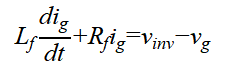
where:
- Lf= filter inductance
- Rf= filter resistance
- ig= grid current
- v_inv= inverter output voltage
- vg= utility grid voltage
This equation represents the electrical dynamics of the filter inductor connected between the inverter and the grid [2].
The transfer function of the filter circuit is:
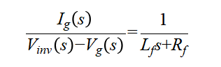
This transfer function is used during controller design and stability analysis.
IX. Discussion
The simulation and real-time results demonstrate that the developed single-phase inverter system achieves stable and reliable operation under grid-connected conditions. The PLL effectively tracks the utility grid phase angle and frequency, enabling accurate synchronization between the inverter current and the grid voltage.
The PI controller provides excellent current tracking performance with minimal steady-state error and stable transient response. The inverter output current remains sinusoidal with low distortion due to the filtering action of the output inductor.
The Hardware-in-the-Loop implementation using RT Box platforms successfully validates the real-time execution capability of the developed model. The separation of the plant and controller subsystems significantly improves computational efficiency and facilitates rapid control prototyping for future experimental applications.
X. Conclusion
This paper presented the modeling, simulation, and real-time implementation of a single-phase grid-connected inverter using the PLECS RT Box platform. The developed inverter system incorporates an H-bridge converter topology, PLL synchronization system, PI current controller, and PWM switching strategy.
The simulation and real-time results confirmed accurate grid synchronization, stable current regulation, and reliable active power injection into the utility grid. The proposed controller architecture achieved unity power factor operation and demonstrated robust performance under real-time Hardware-in-the-Loop conditions.
The developed model provides an effective platform for advanced inverter control research, rapid control prototyping, and future experimental validation of renewable energy conversion systems.
References
[1] R. Teodorescu, M. Liserre, and P. Rodriguez, Grid Converters for Photovoltaic and Wind Power Systems. Hoboken, NJ, USA: Wiley-IEEE Press, 2011.
[2] J. Allmeling and N. Felderer, “Sub-cycle average models with integrated diodes for real-time simulation of power converters,” in Proc. IEEE Southern Power Electronics Conference (SPEC), 2017.
[3] Plexim GmbH, “Single-Phase Inverter RT Box Demo Model Documentation,” Zurich, Switzerland, 2023.
[4] S. Golestan, J. Guerrero, and J. Vasquez, “Single-phase PLLs: A review of recent advances,” IEEE Transactions on Power Electronics, vol. 32, no. 12, pp. 9013–9030, Dec. 2017.
[5] D. Holmes and T. Lipo, Pulse Width Modulation for Power Converters: Principles and Practice. Hoboken, NJ, USA: Wiley-IEEE Press, 2003.
[6] B. Wu, High-Power Converters and AC Drives. Hoboken, NJ, USA: Wiley-IEEE Press, 2006.
[7] H. Rashid, Power Electronics: Circuits, Devices, and Applications. Upper Saddle River, NJ, USA: Pearson Education, 2014.
You can download the Project files here: Download files now. (You must be logged in).


Responses