

Trapezoidal Control of a Brushless DC (BLDC) Motor Using PLECS RT Box with LaunchPad–Nucleo Interface for Real-Time Hardware-in-the-Loop Validation
Author: Waqas Javaid
Abstract
This paper presents the modeling, implementation, and real-time validation of a brushless DC (BLDC) motor drive system using the PLECS RT Box in conjunction with a LaunchPad–Nucleo interface. The system employs trapezoidal (six-step) commutation control executed on a microcontroller unit (MCU), while the plant model is executed on the RT Box to enable hardware-in-the-loop (HIL) operation. The BLDC drive consists of a three-phase inverter, a 24 V DC supply, a permanent magnet BLDC machine, and a mechanical load modeled using inertia and friction. Rotor position is obtained using Hall-effect sensors spaced at 120 electrical degrees, enabling sector-based commutation. The controller implements discrete current regulation and switching logic based on Hall sensor decoding. The system is validated under steady-state and dynamic conditions, demonstrating correct commutation, stable current tracking, and proper synchronization between electrical and mechanical subsystems. The results confirm that the PLECS RT Box combined with MCU-based control provides an effective platform for real-time electric drive testing and embedded system verification.
I. Introduction
Brushless DC (BLDC) motors have gained significant popularity in industrial, automotive, robotics, and aerospace applications due to their high efficiency, simple construction, and excellent torque-to-weight ratio. Unlike conventional DC motors, BLDC machines eliminate mechanical commutators and brushes, thereby reducing maintenance requirements and improving operational lifespan. However, this advantage introduces the requirement for electronic commutation, which is typically achieved using power electronic inverters and digital control systems.
One of the most widely used control strategies for BLDC motors is trapezoidal or six-step commutation control. This method divides one electrical cycle into six sectors of 60 electrical degrees, where only two phases are energized at any time while the third phase remains inactive. This results in a quasi-square wave current waveform that produces constant torque under ideal conditions. The sector identification is typically performed using Hall-effect sensors placed inside the motor at 120 electrical degree spacing.
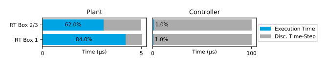
Figure 1: System Overview of BLDC RT Box Execution
Figure 1 presents the execution performance of plant and controller subsystems on RT Box hardware. It demonstrates computational load distribution, where the plant consumes significantly higher processing time due to inverter switching and motor dynamics, while the controller executes efficiently with minimal load. With the advancement of embedded systems and real-time simulation tools, modern BLDC control systems are increasingly validated using hardware-in-the-loop (HIL) environments. The PLECS RT Box provides a powerful platform for such applications, enabling real-time execution of electrical machine models with precise timing constraints. In this framework, the plant (motor and inverter) is simulated on the RT Box, while the controller is implemented either on a microcontroller or a second RT Box.
This paper presents a complete BLDC drive system implemented using PLECS RT Box and LaunchPad–Nucleo interface hardware. The system is designed to replicate real industrial motor control conditions, including current sensing, PWM generation, Hall sensor decoding, and digital I/O interfacing. The objective is to validate trapezoidal control under real-time constraints and demonstrate correct synchronization between plant and embedded controller.
II. System Modeling of BLDC Drive
A. Electrical Model of BLDC Machine
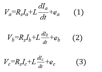
The phase voltage equations of the BLDC machine are expressed as [1][2]:
Variable Definitions
- Va, Vb, Vc: phase voltages (V)
- Ia, Ib, Ic: phase currents (A)
- Rs: stator resistance (Ω)
- L: phase inductance (H)
- ea, eb, ec: back EMF voltages (V)
The back EMF is trapezoidal in nature and depends on rotor position.
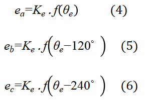
B. Back EMF Model [2][3]
Variables
- Ke: back EMF constant
- θe: electrical rotor position
- f(.): trapezoidal waveform function
C. Electromagnetic Torque [4]
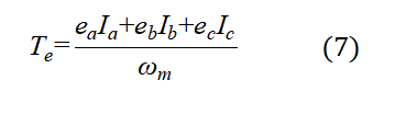
Variables
- Te: electromagnetic torque (Nm)
- ωm: mechanical speed (rad/s)
D. Mechanical Dynamics [1][5]
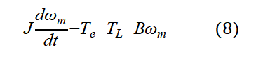
Variables
- J: moment of inertia
- T_L: load torque
- B: viscous friction coefficient
III. Trapezoidal Control Strategy
A. Six-Step Commutation Principle
The BLDC motor is controlled using a six-step commutation method, where each electrical cycle is divided into six sectors of 60° electrical angle. In each sector, two phases are energized while the third phase remains floating.
Hall sensor signals are used to determine rotor position, which is mapped into a sector index.
B. Hall Sensor-Based Position Detection[2]
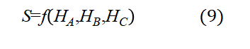
Variables
- S: sector number (1–6)
- H_A, H_B, H_C: Hall sensor states
C. Current Regulation
A discrete PI controller is used [5][6]:
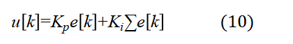
Variables
- u[k]: control output (PWM duty)
- e[k]: current error
- Kp, Ki: controller gains
D. Switching Logic
This logic selects active inverter switches [2][3].
IV. System Architecture in PLECS
A. Plant Subsystem
The plant subsystem represents the physical power and electromechanical components of the brushless DC (BLDC) drive system implemented in PLECS. It consists of a 24 V DC supply that feeds a three-phase voltage source inverter (VSI), which is responsible for generating controlled switching voltages required for motor operation. The inverter is modeled using power electronic switches that replicate real switching behavior, including conduction and commutation dynamics. The output of the inverter is connected to a BLDC motor model, which simulates the electrical and mechanical behavior of the machine, including back electromotive force (EMF), phase currents, and torque generation. The mechanical side of the system includes a load modeled as a combination of inertia and viscous friction, which represents realistic shaft dynamics and load disturbances.
In addition to the power and mechanical components, the plant subsystem also includes Hall sensor emulation, which generates rotor position feedback signals based on the electrical angle of the motor. These Hall signals are essential for sector detection and commutation in trapezoidal control. Furthermore, a current sensing model is implemented to replicate the behavior of the TI DRV8301-based measurement system, where stator currents are measured using low-side shunt resistors and scaled to match real hardware characteristics. This ensures that the simulation environment closely reflects real-world hardware conditions, enabling accurate validation of the control algorithm under realistic sensing and actuation constraints.
B. Controller Subsystem
The controller subsystem implements the complete digital control strategy for the BLDC motor drive system. It is responsible for processing feedback signals received from the plant and generating appropriate switching commands for the inverter. The controller begins with Hall signal decoding logic, where the three digital Hall sensor inputs are interpreted to determine the rotor position and identify the current commutation sector. Based on this information, the sector detection algorithm divides one electrical cycle into six distinct regions, enabling correct phase excitation sequence for trapezoidal operation.
Once the rotor sector is identified, the active phase selection logic determines which two phases of the motor should be energized while the third phase remains inactive. This is followed by a PI current regulator, which controls the magnitude of the phase current by minimizing the error between reference and measured currents. The output of the PI controller is used to adjust the PWM duty cycles, ensuring proper current tracking and torque control. Finally, the PWM generation logic produces gating signals for the inverter switches, while an enable/disable logic block controls the overall operation of the drive system, allowing safe startup, shutdown, and fault handling. Together, these control components ensure stable commutation, accurate current regulation, and reliable operation of the BLDC drive system under real-time conditions.
C. Real-Time Execution Requirement
Ensuring deterministic real-time execution on RT Box [5][7].
V. PLECS RT Box Implementation
A. System Partitioning
The implementation of the BLDC drive system on the PLECS RT Box is based on a modular architecture where the complete system is divided into two main subsystems: the plant subsystem and the controller subsystem. The plant subsystem is executed on the RT Box hardware and represents the physical behavior of the drive system, including the three-phase inverter, BLDC motor dynamics, DC supply, and mechanical load. This subsystem is responsible for accurately reproducing the electrical and mechanical response of the system in real time, ensuring that switching behavior, current dynamics, and rotor motion are realistically modeled under strict timing constraints.
The controller subsystem is executed either on a microcontroller unit (MCU), such as the TI LaunchPad, or on a second RT Box in more advanced configurations. This subsystem implements the complete control algorithm, including Hall sensor decoding, sector detection, current regulation, and PWM generation. The separation of plant and controller enables hardware-in-the-loop (HIL) simulation, where a real embedded controller interacts with a simulated power stage. This architecture allows safe testing of control algorithms under realistic operating conditions without requiring physical power hardware, significantly improving development efficiency and system reliability.
B. Communication Interface
The interaction between the plant and controller subsystems is achieved through a well-defined communication interface that replicates real hardware signal exchange. Analog signals are used to transmit measured phase currents (Ia, Ib, Ic) from the plant to the controller, ensuring accurate feedback for current regulation. Digital signals are used for Hall sensor outputs, which provide rotor position information required for commutation and sector identification. These signals emulate real Hall-effect sensor behavior in physical BLDC machines and are essential for proper trapezoidal control operation.
In addition to measurement signals, PWM gating signals generated by the controller are transmitted back to the plant subsystem to control the switching states of the inverter. Enable and disable control signals are also exchanged to manage safe startup and shutdown of the drive system. Furthermore, status indicators such as LED signals and switch inputs are incorporated into the interface to provide real-time monitoring and user interaction capabilities. This structured communication framework ensures synchronized operation between plant and controller while maintaining real-time determinism and accurate emulation of embedded motor drive systems.
C. Hardware Emulation
The BLDC drive system also incorporates hardware emulation techniques to closely replicate the behavior of real industrial motor control hardware. In particular, the current sensing mechanism is modeled based on the TI BOOSTXL DRV8301 evaluation board, which utilizes low-side shunt resistors for phase current measurement. In the PLECS implementation, this behavior is emulated by scaling and offsetting the simulated current signals to match the characteristics of real analog-to-digital conversion circuits used in hardware systems.
This emulation ensures that the controller experiences realistic measurement noise, scaling factors, and signal conditioning effects similar to those found in practical applications. As a result, the control algorithm can be validated under conditions that closely resemble real-world hardware limitations. This approach improves the robustness of the controller design and ensures that the system performance observed in simulation can be reliably transferred to physical implementation without significant modification.
VI. Simulation in PLECS
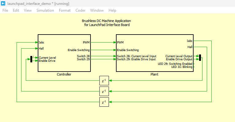
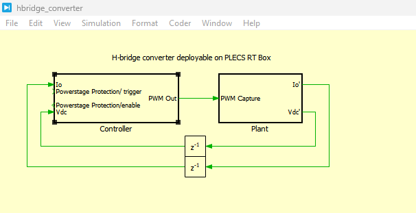
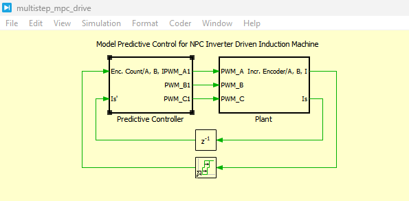
Figure 2: Plant and Controller Subsystem Architecture implemented in PLECS
You can download the Project files here: Download files now. (You must be logged in).
Figure 2 presents the top-level architecture of the BLDC drive system implemented in PLECS, clearly separating the model into plant and controller subsystems. The plant subsystem represents the physical system, including the DC supply, three-phase inverter, BLDC motor, and mechanical load, while the controller subsystem implements the trapezoidal control algorithm. This separation enables modular simulation and supports hardware-in-the-loop (HIL) execution, where each subsystem can be deployed independently on RT Box or MCU hardware. The architecture ensures clean signal interfacing between power stage and control logic, allowing realistic validation of embedded motor control strategies.
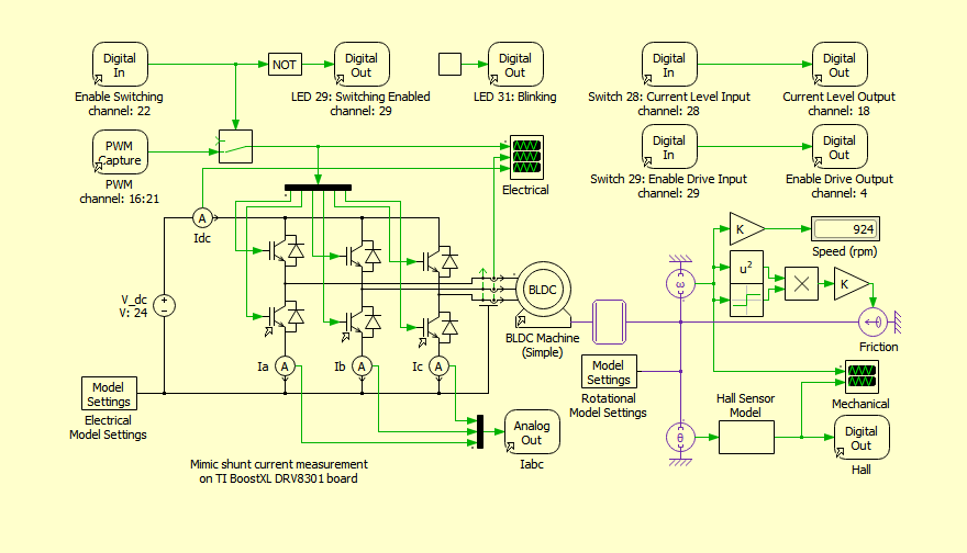
Figure 3: BLDC Drive Power Circuit implemented in PLECS Simulation
Figure 3 illustrates the detailed power circuit of the BLDC drive system developed in PLECS. It consists of a 24 V DC source feeding a three-phase voltage source inverter (VSI), which drives the BLDC motor. The inverter is modeled using semiconductor switching devices that replicate real switching behavior under PWM control. The motor is connected to a mechanical load modeled using inertia and friction components, representing realistic shaft dynamics. This circuit forms the physical layer of the system and is responsible for generating electromagnetic torque based on inverter switching states and back EMF interaction.
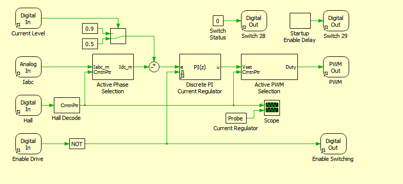
Figure 4: Controller Logic Implementation in PLECS simulation
Figure 4 presents the complete controller logic used for BLDC motor operation. The control system processes Hall sensor inputs to determine rotor position and identify the current commutation sector. Based on this sector information, active phase selection logic determines which motor phases should be energized. A discrete PI controller regulates the phase current by minimizing the error between reference and measured values. The controller then generates PWM signals to drive the inverter switches, while additional logic handles enable/disable operations for safe system startup and shutdown.
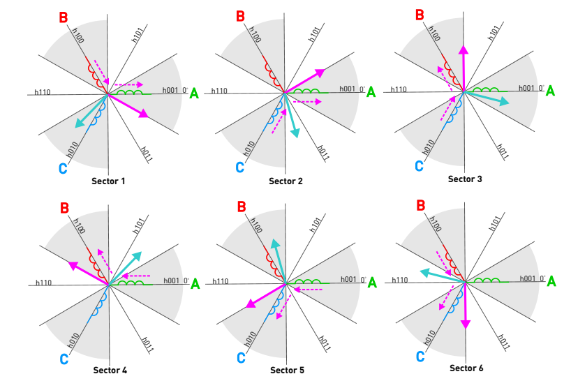
Figure 5: Six-Step Commutation Sequence
Figure 5 illustrates the six-step commutation strategy used in trapezoidal control of the BLDC motor. The electrical cycle is divided into six sectors, each spanning 60 electrical degrees. In each sector, two phases are energized while the third phase remains inactive, producing a rotating magnetic field in discrete steps. Hall sensor signals determine the rotor position and trigger switching between sectors. This sequence ensures continuous torque production and maintains synchronization between stator magnetic field and rotor position.
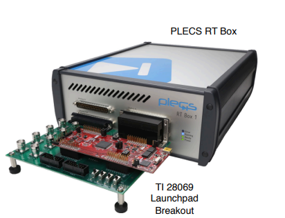
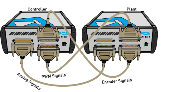
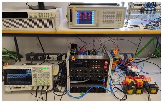
Figure 6: Hardware Connection Setup
Figure 6 shows the physical hardware connection between the PLECS RT Box and the LaunchPad–Nucleo interface used for real-time operation. The RT Box acts as the plant simulator, while the LaunchPad microcontroller executes the control algorithm. Communication is established through analog and digital I/O channels, including current feedback, Hall sensor signals, and PWM gating signals. This setup enables hardware-in-the-loop testing, allowing the embedded controller to interact with a real-time simulated motor drive system.
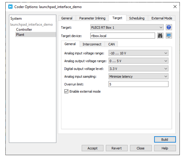
Figure 7: RT Box Programming Interface
Figure 7 presents the RT Box programming interface used to deploy the BLDC plant model onto real-time hardware. Through the PLECS Coder environment, the simulation model is compiled into executable code and downloaded to the RT Box. This interface also allows configuration of target devices, execution parameters, and real-time constraints. Successful deployment is confirmed through system status indicators and execution monitoring tools, ensuring correct real-time operation of the plant subsystem.
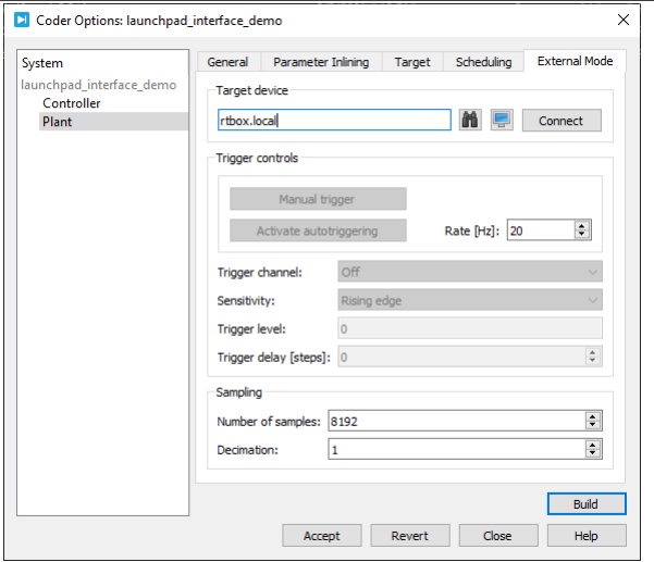
Figure 8: External Mode Communication
You can download the Project files here: Download files now. (You must be logged in).
Figure 8 illustrates the external mode communication setup between the PLECS environment and the RT Box hardware. This mode enables real-time monitoring and parameter tuning while the simulation is running on hardware. Signals such as currents, PWM outputs, and Hall states can be visualized using scopes in PLECS. External mode also allows dynamic modification of controller parameters, making it a powerful tool for debugging and performance analysis during hardware-in-the-loop testing.
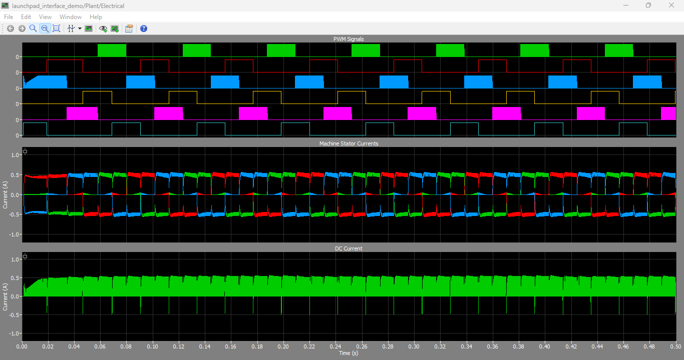
Figure 9: PWM Signals, Stator Current Waveforms and DC current waveforms
Figure 9 presents the simulation waveforms of PWM switching signals, stator phase currents, and DC-link current. The PWM signals demonstrate proper switching behavior of the inverter, while the stator currents exhibit the expected trapezoidal waveform characteristics of BLDC operation. The DC current waveform reflects the power drawn from the DC supply and varies according to load and switching states. These results confirm correct inverter operation and effective current control under trapezoidal commutation.
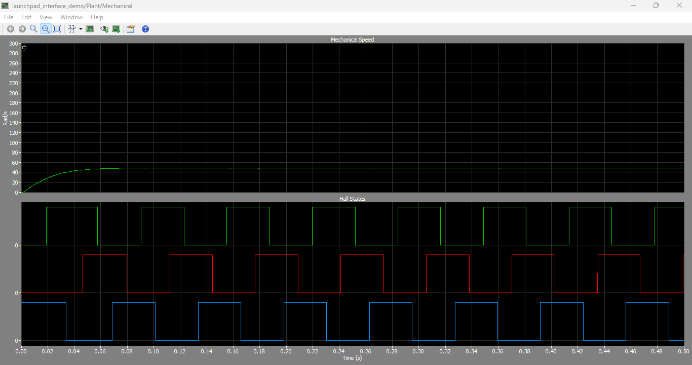
Figure 10: Mechanical Speed and Hall States wave forms
Figure 10 shows the mechanical speed response of the BLDC motor along with corresponding Hall sensor state transitions. The speed waveform demonstrates smooth acceleration and stable steady-state operation under load. The Hall signals change every 60 electrical degrees, confirming correct rotor position detection and sector identification. The synchronization between speed and Hall transitions validates the accuracy of the commutation logic and mechanical modeling.
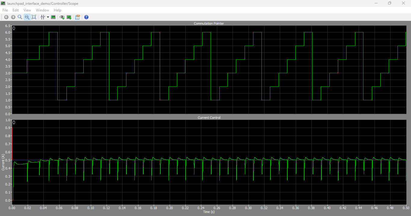
Figure 11: Commutation Pointer and Current control waveforms
You can download the Project files here: Download files now. (You must be logged in).
Figure 11 presents the commutation pointer signal along with controlled current waveforms of the BLDC motor. The commutation pointer indicates the active sector selection used for switching logic, while the current waveforms show regulated phase currents under PI control. The results demonstrate proper alignment between control logic and electrical commutation, ensuring stable torque production and smooth motor operation across all sectors.
VII. Results and Discussion
The simulation and real-time execution results of the BLDC drive system confirm the correct implementation of trapezoidal (six-step) commutation control using the PLECS RT Box platform. The stator current waveforms exhibit the expected two-phase conduction pattern, where at any instant two phases are actively conducting while the third phase remains in a floating condition. This behavior directly validates the correctness of the switching logic implemented in the controller subsystem and confirms that the inverter gating signals are being generated according to the Hall sensor-based sector identification scheme.
The Hall sensor-based rotor position detection plays a critical role in ensuring accurate commutation. The results demonstrate that the Hall signals transition precisely every 60 electrical degrees, which corresponds to correct sector segmentation of the electrical cycle. This accurate detection ensures proper alignment between rotor position and stator magnetic field, allowing smooth torque production throughout the operation. Any misalignment in Hall decoding would lead to torque ripple or incorrect phase energization; however, the obtained results confirm stable and reliable sector detection throughout the simulation.
The PI current controller demonstrates strong dynamic performance by maintaining stable current regulation under both steady-state and transient conditions. During commutation transitions, where current switching naturally introduces disturbances, the controller effectively reduces current ripple and ensures smooth tracking of reference values. This confirms that the selected proportional and integral gains are properly tuned for the BLDC drive system. The controller successfully compensates for system nonlinearities introduced by back EMF variations and switching dynamics, ensuring consistent torque output.
Furthermore, the RT Box platform successfully executes the plant model in real time without violating computational timing constraints. The execution time remains within the defined sampling period, confirming deterministic real-time performance. This demonstrates that the system is suitable for hardware-in-the-loop applications where strict timing accuracy is required. The stable processor utilization also confirms that the model is well optimized for real-time deployment.
Overall, the hardware-in-the-loop (HIL) configuration significantly enhances the validation process by allowing the embedded MCU-based controller to interact with a high-fidelity simulated plant. This eliminates the need for physical motor testing during early development stages, reducing both cost and risk. It also enables safe testing under fault conditions and extreme operating scenarios that would otherwise be difficult to reproduce in a laboratory environment.
VIII. Conclusion
This paper presented the design, implementation, and real-time validation of a brushless DC (BLDC) motor drive system using the PLECS RT Box platform integrated with a LaunchPad–Nucleo interface. The system implements a trapezoidal control strategy based on Hall sensor feedback, enabling six-step commutation of the inverter to achieve controlled torque production. The complete drive system is divided into plant and controller subsystems, allowing independent execution and facilitating hardware-in-the-loop (HIL) operation.
The results demonstrate that the proposed system achieves accurate rotor position tracking, correct commutation sequencing, and stable current regulation under both steady-state and dynamic conditions. The stator current waveforms confirm proper two-phase conduction behavior, while the Hall sensor signals ensure reliable sector detection. The PI current controller provides effective regulation of phase currents, minimizing ripple and maintaining system stability even during switching transitions.
The modular architecture of the system allows seamless integration between simulation and embedded hardware platforms. This flexibility makes the proposed approach highly suitable for industrial motor drive development, where rapid prototyping and real-time validation are essential. The use of the PLECS RT Box significantly enhances development efficiency by enabling accurate real-time simulation of power electronic systems without requiring physical hardware during early stages.
Future work will focus on improving the performance of the BLDC drive system by implementing sensorless control techniques, which eliminate the need for Hall sensors and reduce system cost and complexity. Additionally, advanced modulation strategies such as space vector pulse width modulation (SVPWM) and model-based predictive control (MPC) will be explored to further reduce torque ripple, improve efficiency, and enhance dynamic response under varying load conditions.
References
[1] R. Krishnan, Electric Motor Drives: Modeling, Analysis, and Control, Prentice Hall, 2001.
[2] B. K. Bose, Modern Power Electronics and AC Drives, Prentice Hall, 2002.
[3] Texas Instruments, “Sensorless Trapezoidal Control of BLDC Motors,” Application Report, 2015.
[4] P. C. Krause, Analysis of Electric Machinery and Drive Systems, Wiley, 2013.
[5] K. Ogata, Modern Control Engineering, Prentice Hall, 2010.
[6] G. F. Franklin, J. D. Powell, Digital Control of Dynamic Systems, Addison-Wesley, 2015.
[7] Plexim GmbH, “PLECS RT Box Target Support Package Documentation,” 2023.
You can download the Project files here: Download files now. (You must be logged in).


Responses