

Rainflow Counting and Lifetime Prediction of IGBT Power Modules in Direct Torque Controlled Induction Motor Drives Using PLECS Simulation


Author: Waqas Javaid
Abstract
The reliability and lifetime prediction of power semiconductor devices are critical in modern electric drive systems, particularly in industrial induction motor (IM) drives using direct torque control (DTC). This paper presents a comprehensive analysis of rainflow counting-based lifetime estimation for insulated gate bipolar transistor (IGBT) power modules using a PLECS simulation environment. The study focuses on thermal cycling effects in semiconductor junction temperatures under different load profiles defined by IEC 60034-1 duty cycles. A transient electro-thermal model is used to extract junction temperature profiles, which are subsequently processed using a rainflow counting algorithm based on ASTM fatigue standards. The extracted thermal cycles are used to compute damage accumulation via Miner’s rule, enabling lifetime estimation of the power module. Results show that periodic load variations significantly reduce IGBT lifetime compared to constant load operation. The study demonstrates that electro-thermal stress, rather than average operating temperature, dominates device degradation mechanisms in inverter-based motor drives.
1. Introduction
Power semiconductor devices such as IGBTs are widely used in motor drive applications due to their high efficiency, fast switching capability, and robustness. However, their reliability is strongly influenced by thermal stress caused by power losses during switching and conduction operations. In industrial induction motor drives controlled by Direct Torque Control (DTC), rapid torque variations lead to dynamic current changes, resulting in fluctuating junction temperatures in semiconductor devices [3].
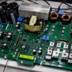
Figure A: IGBT Modules which detects rain flow lifetime predition in DTC IM drives.
Figure A presents the IGBT power modules used in the Direct Torque Controlled (DTC) induction motor drive for rainflow-based lifetime prediction. The IGBT modules serve as the main switching devices in the three-phase inverter, converting the DC-link voltage into controlled AC voltages required to drive the induction motor. During operation, the IGBTs experience conduction and switching losses, which generate heat and cause variations in the junction temperature.
These junction temperature fluctuations are continuously monitored through the electro-thermal model developed in PLECS. The resulting temperature profile is processed using the rainflow counting algorithm, which identifies individual thermal cycles and their amplitudes. The extracted thermal cycles are then used with a fatigue model and Miner’s damage accumulation rule to estimate the remaining useful lifetime of the IGBT module.
The figure A illustrates the practical hardware component whose thermal behavior forms the basis of the lifetime prediction process. By accurately analyzing the thermal stress experienced by the IGBT modules under different motor load conditions, the proposed method enables reliable assessment of semiconductor degradation and supports predictive maintenance strategies for DTC induction motor drive systems.
Thermal cycling is one of the dominant failure mechanisms in IGBT modules. Repeated temperature swings between on-state and off-state operation cause mechanical fatigue in wire bonds, solder layers, and substrate materials. To estimate the lifetime of these devices, advanced statistical methods such as rainflow counting are used to analyze thermal stress cycles extracted from transient simulations.
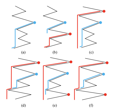
Figure B: Illustration of rainflow started at a current peak (marked by the blue dot): (a) case 1, (b) case 2, (c) case 3, (d) case 4, (e) case 5, and (f) case 6
Figure B presents an illustration of the rainflow counting mechanism initiated at a current peak point (Pcur), which is marked by a blue dot. The figure B demonstrates the six distinct cases that arise during rainflow cycle identification when analyzing junction temperature profiles in power electronic devices.
In this representation, Pcur denotes the current peak under consideration, while Ppre,h,n (previous higher or equal peak) and Psub,h,n (subsequent higher or equal peak) are highlighted in red dots. These reference points are used to determine whether a thermal cycle is completed, interrupted, or extended according to ASTM-based rainflow counting rules.
The six cases shown in subfigures (a) to (f) describe all possible cycle termination scenarios:
- In some cases, neither a valid previous nor subsequent peak exists, causing the rainflow cycle to continue until the end of the signal.
- In other cases, only one of the reference peaks exists, which leads to early termination of the cycle either due to a higher subsequent peak or an earlier intersection point.
- When both previous and subsequent qualifying peaks exist, the algorithm evaluates the valley conditions between them to determine whether the current rainflow is intercepted by a previous cycle or terminated before reaching the next peak.
These six scenarios ensure that all possible geometric configurations of thermal loading are correctly captured, preventing double counting or omission of partial cycles.
Overall, Figure B is critical for understanding the decision logic of the rainflow counting algorithm, as it visually explains how complex junction temperature waveforms are decomposed into discrete fatigue-relevant thermal cycles used for IGBT lifetime estimation.
PLECS (Piecewise Linear Electrical Circuit Simulation) provides a powerful platform for modeling electro-thermal behavior in power electronics systems. The demo model provided by Plexim integrates a DTC-controlled induction motor drive with a thermal model of an IGBT module (PM75CLA060), allowing extraction of junction temperature profiles under different load conditions [1].
This paper investigates the application of rainflow counting and Miner’s rule-based damage accumulation to predict the lifetime of IGBT modules operating under standardized load cycles (S1 and S6). The objective is to evaluate how different mechanical load profiles affect semiconductor reliability.
Literature Review
The reliability assessment of power semiconductor devices has been widely studied in the context of electro-thermal stress and fatigue-driven degradation. In modern power electronic systems such as induction motor drives, the lifetime of insulated gate bipolar transistors (IGBTs) is primarily governed by thermal cycling rather than steady-state temperature rise. As a result, accurate modeling of junction temperature fluctuations and their conversion into fatigue damage has become a critical research focus.
Early studies in power electronics reliability established that thermal cycling induces mechanical stress in bonding wires, solder layers, and chip metallization interfaces, ultimately leading to device failure. Manufacturers such as Mitsubishi Electric have provided extensive power cycling test data for IGBT modules, including the PM75CLA060 device, which defines the relationship between temperature swing and number of cycles to failure [1]. These empirical curves form the foundation for most lifetime prediction models used in industry.
A widely adopted approach for fatigue analysis is the rainflow counting method, originally developed for mechanical stress analysis and later adapted for thermal cycling in electronics. The method was standardized by ASTM and is now commonly used in semiconductor reliability studies to extract equivalent thermal cycles from complex, non-periodic temperature waveforms. Its application to power electronics allows irregular junction temperature profiles to be decomposed into discrete damage-relevant cycles, enabling accurate lifetime estimation.
In recent literature, rainflow-based methods have been increasingly integrated with electro-thermal simulation tools such as PLECS and MATLAB/Simulink. These tools enable detailed modeling of inverter switching behavior, motor load dynamics, and thermal network response. Studies have shown that transient electro-thermal simulations provide significantly more realistic lifetime predictions compared to simplified average-loss models, especially in applications with dynamic loading such as electric drives and renewable energy converters [3].
Another important advancement in the field is the use of Miner’s rule for cumulative damage estimation. This linear damage accumulation model allows multiple thermal cycles of different amplitudes to be combined into a single damage index, providing a practical approach for lifetime estimation under variable operating conditions. Although Miner’s rule assumes linear damage accumulation and does not account for sequence effects, it remains widely used due to its simplicity and acceptable accuracy in engineering applications [2].
Direct Torque Control (DTC) based induction motor drives have also been extensively studied in relation to power semiconductor stress. DTC systems are known for producing rapid torque and flux variations, which lead to high-frequency current ripple and corresponding junction temperature fluctuations. Research has demonstrated that load profiles defined by IEC 60034-1, particularly S1 (constant load) and S6 (periodic load), significantly influence thermal cycling severity and device degradation rates.
More recent contributions in literature focus on improving lifetime prediction accuracy through advanced filtering techniques, such as periodic averaging of junction temperature signals to remove switching-frequency noise. This ensures that only meaningful thermal cycles contributing to fatigue damage are considered in rainflow analysis. Additionally, research has explored coupling rainflow algorithms with real-time monitoring systems for predictive maintenance of power electronic systems.
Overall, existing studies confirm that the combination of electro-thermal simulation, rainflow counting, and Miner’s rule provides a robust framework for IGBT lifetime estimation. However, the accuracy of prediction strongly depends on the quality of thermal modeling, load profile definition, and filtering of temperature data. This paper builds upon these established methodologies by implementing a PLECS-based simulation framework to evaluate IGBT lifetime under standardized DTC motor drive conditions.
3. System Overview and Modeling Approach
The studied system consists of a three-phase voltage source inverter (VSI) feeding an induction motor controlled by a DTC algorithm. The inverter uses IGBT modules with integrated thermal modeling to simulate junction temperature behavior under electrical and mechanical loading conditions.
The system includes the following subsystems:
- Electrical inverter circuit with switching IGBTs
- DTC control block for torque regulation
- Mechanical induction motor model
- Thermal network representing junction-to-case and case-to-heatsink behavior
- Signal monitoring for temperature extraction
A key feature of the simulation is the inclusion of a Signal Outport block, which exports junction temperature and simulation time to an external script for post-processing.
To eliminate high-frequency switching noise in the temperature waveform, a 1 ms periodic averaging filter is applied. This ensures that only meaningful thermal cycles contributing to fatigue damage are analyzed.
The IGBT module used is Mitsubishi PM75CLA060, whose power cycling capability is used as a reference for lifetime estimation [1].
4. Rainflow Counting Methodology
4.1 Principle of Rainflow Counting
The rainflow counting method is a standard technique used in fatigue analysis to extract cyclic loading information from irregular stress or temperature signals. It converts a complex thermal waveform into discrete cycles characterized by amplitude and mean values.
In the context of power electronics, the junction temperature waveform is analyzed to identify thermal cycles that contribute to material fatigue.
The lifetime model is expressed using an empirical power-law relationship [5]:
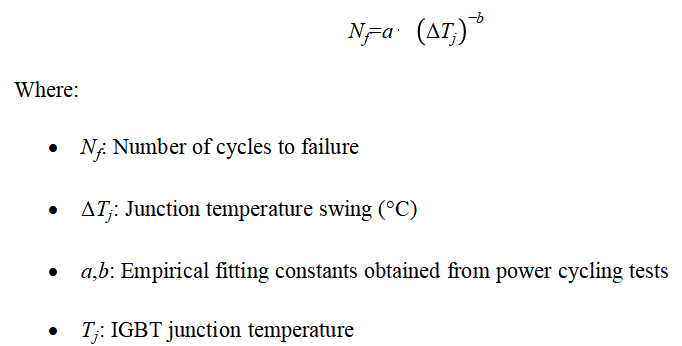
Equation (1) indicates that higher temperature swings significantly reduce device lifetime due to accelerated material degradation.
4.2 Cycle Extraction Rules
The rainflow algorithm follows ASTM fatigue counting standards and identifies peaks and valleys in the temperature waveform. The process involves:
- Extracting local maxima and minima from
- Pairing cycles based on amplitude reversal
- Applying termination conditions based on future and past peaks
- Classifying full and half cycles
The algorithm ensures that overlapping thermal cycles are not double counted. Six primary cases are considered depending on the relationship between current peaks and neighboring extrema.
4.3 Damage Accumulation Using Miner’s Rule
The total damage caused by multiple thermal cycles is calculated using Miner’s linear damage rule [6]:
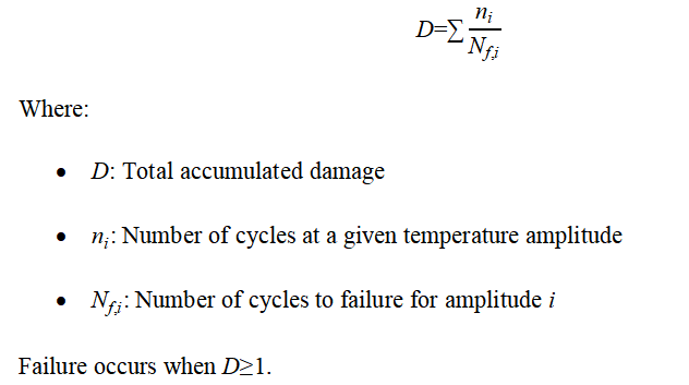
This method enables the combination of multiple stress levels into a single equivalent lifetime estimation.
5. Simulation Setup
The simulation is based on the PLECS demo model “Rainflow Counting and Lifetime Prediction” version 4.6.1 [1]. The induction motor is operated at a constant speed of 180 rad/s under two load conditions defined by IEC 60034-1 standard [3]:
5.1 Load Profile S1 (Constant Load)
- Constant torque: 40 Nm
- Steady-state operation
- Minimal thermal variation
- Represents industrial continuous operation
5.2 Load Profile S6 (Periodic Load)
- Torque varies between 20 Nm and 60 Nm
- Duty cycle: 0.5
- Period: 5 seconds
- Represents cyclic industrial load conditions
6. Thermal Behavior and Results
6.1 Start-Up Thermal Transient
During startup, high inrush current causes rapid heating of IGBT junctions. The heat sink, due to its high thermal capacitance, takes approximately 7 seconds to reach steady-state temperature. This transient phase contributes marginally to lifetime consumption but is excluded from long-term analysis.
6.2 Steady-State Thermal Cycles
Under steady-state operation:
- S1 duty produces small temperature variations (<5°C)
- S6 duty produces large cyclic variations (15–20°C)
These variations significantly influence fatigue damage accumulation.
6.3 Rainflow Analysis Results
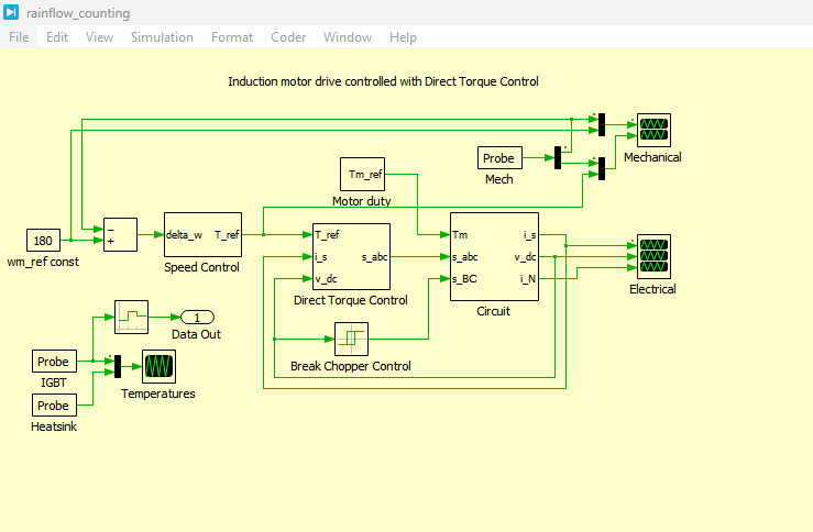
Figure 1: Induction motor drive controlled with Direct Torque Control rainfall counting model developed in PLECS
Figure 1 presents the induction motor drive controlled with Direct Torque Control (DTC) rainflow counting model developed in PLECS, which forms the complete system-level simulation framework. It integrates the electrical inverter, induction motor, thermal model, and rainflow counting-based lifetime estimation algorithm. The model serves as the primary platform for analyzing junction temperature variations and predicting IGBT lifetime under different load conditions.
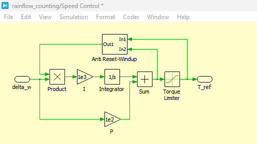
Figure 2: Rainfall counting Speed controller model developed in PLECS
You can download the Project files here: Download files now. (You must be logged in).
Figure 2 presents the rainflow counting speed controller model developed in PLECS, which is responsible for regulating the rotational speed of the induction motor. This subsystem ensures that the motor follows the reference speed profile under varying load torque conditions. The speed controller plays a critical role in generating dynamic load conditions that directly influence the thermal cycling behavior of the IGBT module.
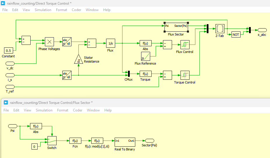
Figure 3: Direct Torque Control and Flux Sector control circuit of Rainfall counting model developed in PLECS
Figure 3 presents the Direct Torque Control (DTC) and flux sector control circuit of the rainflow counting model developed in PLECS, which is used to regulate motor torque and flux independently. This control structure determines inverter switching states based on torque and flux errors. The resulting switching activity introduces variations in current and torque, which directly affect the semiconductor junction temperature profile used in rainflow analysis.
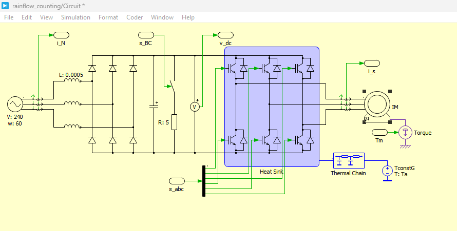
Figure 4: Rainfall counting with driving circuit of induction motor model developed in PLECS
Figure 4 presents the rainflow counting system integrated with the driving circuit of the induction motor model developed in PLECS, showing the complete power electronic interface between the inverter and the motor. This includes the gate driver signals, inverter bridge, and thermal network. The configuration enables accurate electro-thermal coupling, allowing realistic simulation of IGBT temperature swings under operational load conditions.
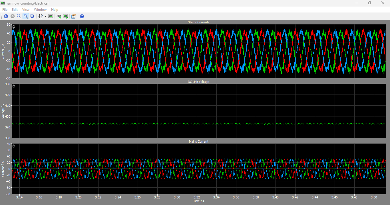
Figure 5: Stator Currents, DC Link Voltage and Mains Currents output graphs generated using PLECS Simulation
You can download the Project files here: Download files now. (You must be logged in).
Figure 5 presents the simulation output waveforms of stator currents, DC-link voltage, and mains currents generated using PLECS, which illustrate the electrical performance of the system under dynamic loading. The stator current waveform reflects torque demand, while DC-link voltage stability indicates proper inverter operation. The mains current profile shows the power drawn from the source and its variation under different operating conditions.
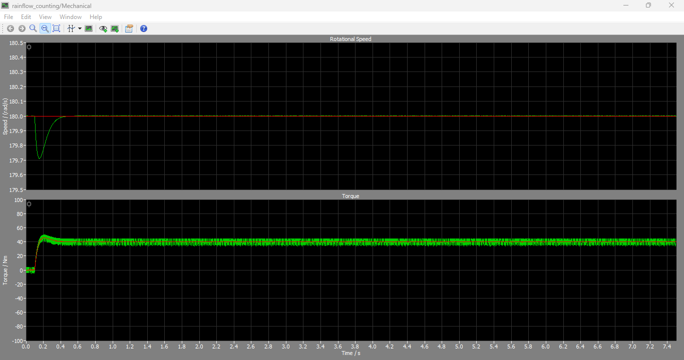
Figure 6: Mechanical properties like Rotational Speeds and Torques output graphs
Figure 6 presents the mechanical performance characteristics including rotational speed and electromagnetic torque obtained from PLECS simulation, demonstrating the dynamic response of the induction motor. The speed response indicates the effectiveness of the DTC speed controller, while the torque waveform shows how load variations are tracked. These mechanical variations directly contribute to thermal cycling in the inverter.
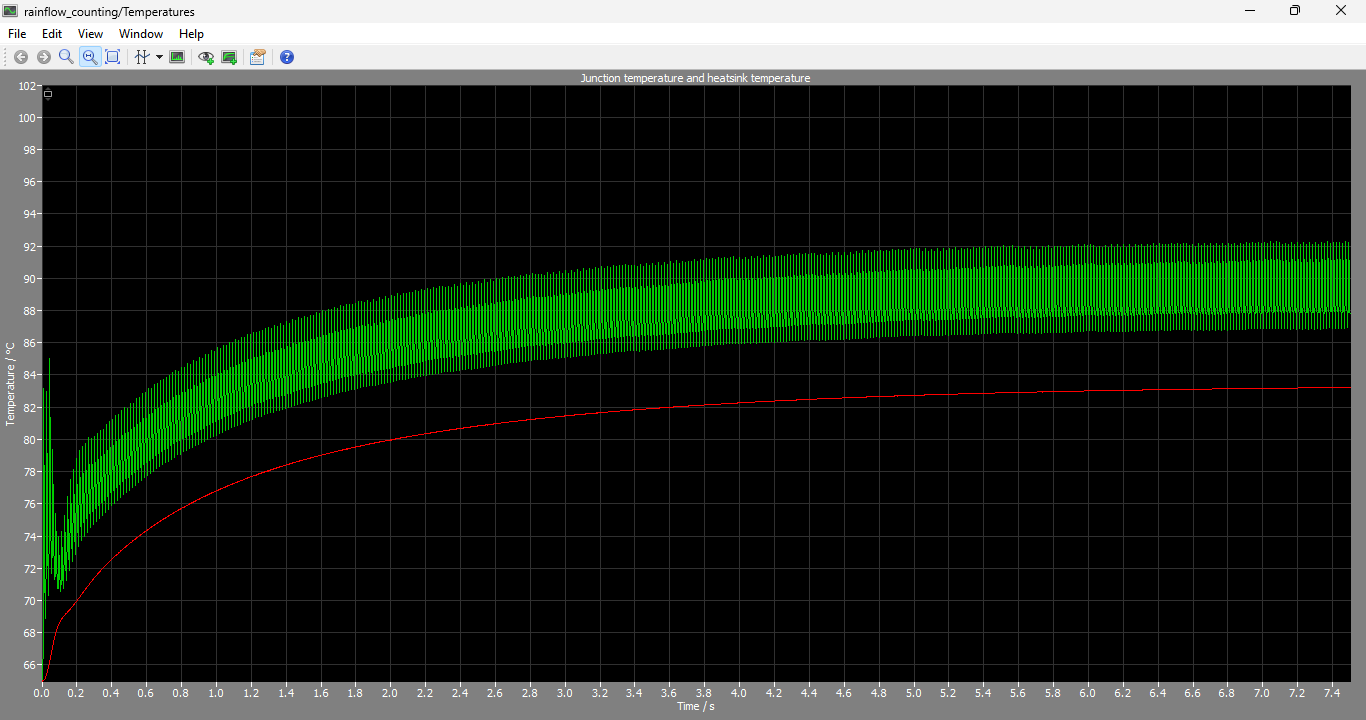
Figure 7: Junction Temperature and Heatsink temperature output graphs
You can download the Project files here: Download files now. (You must be logged in).
Figure 7 presents the junction temperature and heatsink temperature profiles of the IGBT module obtained from PLECS simulation, which are essential for lifetime prediction analysis. The junction temperature shows rapid variations due to switching losses and load changes, while the heatsink temperature exhibits slower thermal dynamics due to higher thermal capacitance. These temperature profiles are the primary input for the rainflow counting algorithm used in fatigue estimation.
The extracted temperature waveform is processed using the rainflow algorithm, producing:
- Peak-valley pairs
- Cycle amplitude histogram
- Cycle frequency distribution
For S1:
- Only one dominant bin (~5°C cycles)
- Approximately 46.5 equivalent cycles per load period
For S6:
- Multiple bins (15°C and 20°C cycles dominate)
- Higher thermal stress concentration
7. Lifetime Prediction Results
Using equation (1) and Miner’s rule (2), lifetime estimation is performed.
7.1 S1 Load Condition
- Small thermal swings
- Low damage accumulation
- Predicted lifetime ≈ 16 years
The system operates in a thermally safe region where degradation is slow.
7.2 S6 Load Condition
- Large periodic thermal swings
- High damage per cycle
- Predicted lifetime ≈ 1 years
This demonstrates that cyclic loading dramatically accelerates degradation.
8. Discussion
The results clearly indicate that IGBT lifetime is not governed by average temperature but by thermal swing amplitude and frequency. Even moderate increases in ΔTj significantly reduce expected lifetime due to nonlinear fatigue mechanisms.
Key observations:
- Thermal cycling is more critical than steady-state heating
- Large load fluctuations dominate device degradation
- Small ripple filtering is essential for accurate fatigue prediction
- Rainflow method provides realistic lifetime estimation compared to simple averaging methods
These findings align with industrial reliability studies on power cycling degradation in IGBT modules [2].
9. Conclusion
This paper presented a comprehensive rainflow counting-based lifetime prediction method for IGBT power modules in a DTC-controlled induction motor drive using PLECS simulation. The study demonstrated that thermal cycling plays a dominant role in semiconductor degradation.
The following conclusions were drawn:
- Rainflow counting effectively extracts meaningful thermal cycles from complex temperature waveforms
- Miner’s rule provides a reliable damage accumulation model
- Periodic load conditions significantly reduce IGBT lifetime compared to constant load operation
- Accurate electro-thermal modeling is essential for predictive reliability analysis
Future work may include aging-aware control strategies and real-time thermal monitoring for predictive maintenance in industrial drives.
References
[1] MITSUBISHI Electric, “PM75CLA060FLAT-B Datasheet,” 2021.
[2] Mitsubishi Electric, “PV-IPM Application Note,” 2021.
[3] IEC Standard 60034-1, “Rotating Electrical Machines – Duty Cycles,” International Electrotechnical Commission, 2020.
[4] Plexim GmbH, “PLECS Demo Model: Rainflow Counting and Lifetime Prediction,” PLECS 4.6.1 Documentation, 2023.
[5] M. Held, J. Jacob, P. Nicoletti, P. Scacco, and M. Poech, “Fast power cycling test for IGBT modules in traction application,” Proceedings of the International Conference on Power Electronics and Drive Systems (PEDS), 1997, pp. 425–430.
[6] M. A. Miner, “Cumulative damage in fatigue,” Journal of Applied Mechanics, vol. 12, no. 3, pp. A159–A164, 1945.
You can download the Project files here: Download files now. (You must be logged in).







Responses