

State Machine-Based Constant On-Time Control of a Buck Converter Using PLECS Simulation

Author: Waqas Javaid
Abstract
Buck converters are among the most widely utilized non-isolated DC-DC power converters due to their high efficiency, simple topology, and ability to regulate output voltage across numerous industrial and consumer applications. As modern electronic systems increasingly demand fast transient response, reduced switching losses, and improved voltage regulation, conventional fixed-frequency pulse-width modulation (PWM) controllers often face limitations under rapidly changing load conditions. Constant On-Time (COT) control has emerged as an attractive alternative because it naturally provides fast dynamic response, simplified control implementation, and variable switching frequency that adapts to operating conditions. This paper presents the modeling, implementation, and simulation of a buck converter employing a Constant On-Time control strategy using the State Machine block available in the PLECS simulation environment. The proposed control architecture consists of an outer proportional-integral (PI) voltage regulation loop and an inner current-based COT controller that governs the switching operation of the power MOSFET. Unlike traditional comparator-based implementations, the proposed controller utilizes an event-driven state machine consisting of ON, OFF, and Ready-for-ON operating states to achieve deterministic switching behavior while enforcing predefined on-time and minimum off-time intervals. The complete converter model is developed in PLECS, enabling detailed analysis of converter dynamics, controller behavior, switching transitions, and output voltage regulation. Simulation results demonstrate stable operation, accurate voltage regulation, rapid response to current variations, and effective implementation of the Constant On-Time algorithm. The presented methodology illustrates how state-machine-based control can simplify digital controller development while improving converter performance, making it suitable for embedded power electronics applications and rapid controller prototyping.
I. Introduction
The rapid advancement of portable electronics, industrial automation, renewable energy systems, electric vehicles, telecommunication infrastructure, and embedded computing has significantly increased the demand for efficient power conversion systems capable of delivering stable voltage under varying operating conditions [1], [2]. DC-DC converters represent one of the most fundamental building blocks of modern power electronic systems because they enable voltage conversion with high efficiency while maintaining compact size and low power dissipation. Among the different converter topologies, the buck converter remains one of the most extensively employed configurations owing to its simplicity, low component count, and excellent efficiency in step-down voltage conversion applications [3].
A buck converter transforms a higher DC input voltage into a lower regulated output voltage using high-frequency switching devices together with passive energy storage elements such as inductors and capacitors. Compared with linear voltage regulators, switching converters significantly reduce conduction losses because the power semiconductor devices operate primarily in either fully ON or fully OFF states. Consequently, switching converters are capable of achieving efficiencies exceeding 90%, making them suitable for battery-operated systems, server power supplies, communication equipment, industrial controllers, and automotive electronics [4].

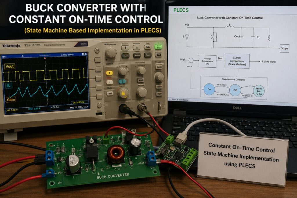
Figure A: Conceptual representation of the proposed buck converter with State Machine-based Constant On-Time (COT) control implemented in the PLECS simulation environment.
Figure A presents a conceptual overview of the proposed Buck Converter with Constant On-Time (COT) control implemented using the PLECS simulation platform. The illustration depicts a practical power electronics development environment comprising a buck converter prototype, a digital oscilloscope displaying the converter output voltage, inductor current, and gate switching waveforms, and a computer executing the PLECS simulation model with the State Machine controller. The proposed control architecture integrates an outer proportional-integral (PI) voltage controller with an inner event-driven Constant On-Time controller to regulate the MOSFET switching operation. This integrated representation highlights the close relationship between simulation-based controller development and practical hardware implementation, emphasizing the effectiveness of the State Machine approach for designing fast, reliable, and digitally controlled DC-DC power converters.
The performance of a buck converter depends heavily on the employed control strategy. Traditional voltage-mode and current-mode Pulse Width Modulation (PWM) controllers operate at fixed switching frequencies and utilize feedback loops to regulate output voltage. Although these methods have been widely adopted due to their predictable switching characteristics, they often require relatively complex compensation networks and may exhibit slower transient responses during abrupt load changes [5]. Furthermore, maintaining stable operation across a broad operating range requires careful controller tuning and compensation design.
To address these challenges, Constant On-Time (COT) control has become an increasingly attractive solution in modern switching power supplies. Instead of maintaining a constant switching frequency, COT control fixes the ON duration of the power switch while allowing the OFF duration to vary according to load requirements. This approach enables exceptionally fast transient response because switching decisions are directly influenced by instantaneous current or voltage errors without waiting for the completion of a fixed switching period [6]. Consequently, COT-controlled converters naturally adapt their switching frequency to operating conditions while maintaining accurate voltage regulation.
One of the distinguishing characteristics of Constant On-Time control is its event-driven nature. Unlike conventional PWM controllers that continuously generate carrier waveforms and compare them with modulation signals, COT controllers initiate switching events whenever predefined operating conditions are satisfied. This significantly reduces computational complexity in digital implementations while simultaneously improving controller responsiveness [7]. Such characteristics make Constant On-Time control particularly suitable for modern digital power converters implemented using microcontrollers, DSPs, or FPGA platforms.
Recent advances in model-based design tools have further simplified the development of sophisticated digital controllers. Among these software platforms, PLECS has become a widely recognized simulation environment for power electronics research because it combines accurate electrical system simulation with intuitive control-system modeling [8]. In addition to conventional control blocks, PLECS provides State Machine components that allow engineers to describe event-driven control algorithms using finite-state representations. These state machines closely resemble embedded firmware implementations, thereby reducing the gap between simulation and practical controller development.
Instead of relying solely on comparator circuits and timing generators, the State Machine implementation enables explicit definition of controller states, transition conditions, timer events, and switching actions. This graphical representation enhances controller readability while improving debugging, verification, and maintenance during system development. Moreover, animation features within PLECS provide valuable visualization of controller execution, allowing designers to observe state transitions and timing events throughout converter operation [9].
The present work focuses on developing a complete buck converter employing a State Machine-based Constant On-Time controller using PLECS. The proposed control architecture consists of two hierarchical feedback loops. The outer loop employs a proportional-integral (PI) controller to regulate output voltage by generating an appropriate current reference. The inner loop compares the measured inductor current with the reference current and determines switching actions using a finite-state machine. Three operating states—ON, OFF, and Ready-for-ON—collectively manage switching events while ensuring fixed ON-time and minimum OFF-time constraints are satisfied.
Unlike many published studies that emphasize analytical controller derivation, this research primarily concentrates on practical implementation and controller realization using model-based simulation techniques. The developed model closely follows the control philosophy adopted in modern digitally controlled power converters while maintaining sufficient simplicity for educational and research applications.
The major contributions of this work can be summarized as follows:
- Development of a complete buck converter model using the PLECS simulation platform.
- Design of a dual-loop control architecture incorporating PI voltage regulation and Constant On-Time current control.
- Implementation of an event-driven switching controller using the PLECS State Machine block.
- Investigation of controller operation through state transition analysis and switching logic.
- Performance evaluation of the proposed controller using transient simulation waveforms.
The remainder of this paper is organized as follows. Section II reviews recent developments in buck converter control techniques and digital implementation strategies. Section III describes the operating principles of the proposed converter and the Constant On-Time control methodology. Section IV presents the PLECS implementation of the state-machine controller together with the PI compensation scheme. Section V discusses simulation results and evaluates converter performance. Finally, Section VI concludes the paper and outlines potential directions for future research.
II. Literature Review
Buck converters have been extensively investigated over the past several decades due to their widespread use in regulated power supplies and energy conversion systems. Continuous improvements in semiconductor technology have enabled converters to operate at higher switching frequencies while achieving improved efficiency and reduced converter size [10]. As switching devices become faster and digital controllers become increasingly powerful, researchers have explored numerous control strategies to improve transient performance, stability, and implementation flexibility.
Traditional voltage-mode PWM control remains one of the earliest and most widely adopted approaches for buck converter regulation. In voltage-mode control, the output voltage is compared with a reference signal, and the resulting error is processed through a compensation network before being compared with a high-frequency carrier waveform to generate switching pulses [11]. Although this technique offers relatively simple implementation, it often exhibits limited transient performance because changes in output voltage require multiple switching cycles before corrective action becomes effective.
Current-mode control was later introduced to improve dynamic performance by incorporating inductor current feedback into the control loop [12]. By directly regulating the energy delivered during each switching cycle, current-mode control significantly improves transient response while simplifying compensation design. Nevertheless, current-mode controllers frequently require slope compensation to avoid subharmonic oscillations at higher duty cycles, increasing controller complexity.
To overcome these limitations, researchers have proposed variable-frequency control techniques such as hysteresis control, valley current control, boundary conduction control, and Constant On-Time control [13]. Among these methods, Constant On-Time control has gained considerable attention because of its inherently rapid response to load disturbances and reduced control latency. Instead of depending on periodic carrier signals, COT controllers initiate switching events immediately when current or voltage conditions require correction.
Several studies have demonstrated that Constant On-Time control provides excellent load regulation, simplified compensation requirements, and reduced computational burden for digitally controlled converters [14]. Furthermore, its event-driven operation makes it highly compatible with finite-state-machine implementations commonly used in embedded control software.
In recent years, digital power electronics has shifted toward model-based controller development using simulation environments capable of integrating electrical systems with embedded control algorithms. PLECS has emerged as one of the leading platforms for this purpose because it provides accurate switching models together with intuitive implementation of digital control logic [15]. The availability of State Machine blocks further enables direct representation of embedded controller firmware within simulation models, allowing comprehensive verification prior to hardware implementation.
Despite the growing popularity of Constant On-Time controllers, relatively few studies provide detailed descriptions of state-machine-based implementations suitable for educational and rapid-prototyping applications. Consequently, this work contributes by presenting a complete PLECS-based realization of a dual-loop Constant On-Time controller employing finite-state logic for deterministic switching control while maintaining accurate output voltage regulation.
III. Proposed Buck Converter With Constant On-Time Control
A. Buck Converter Operating Principle
The buck converter is a non-isolated step-down DC-DC converter designed to convert a higher input DC voltage into a regulated lower output voltage while maintaining high conversion efficiency. The converter operates by periodically switching a power semiconductor device, typically a MOSFET, at high frequency. The switching action controls the transfer of energy from the input source to the load through an inductor-capacitor (LC) filter, which minimizes current and voltage ripple while maintaining continuous power delivery [16].
The proposed converter model consists of a DC voltage source, a power MOSFET, a freewheeling diode, an inductor, an output capacitor, and a resistive load. The switching device is controlled using a Constant On-Time (COT) controller implemented through the PLECS State Machine block. Unlike conventional PWM-based controllers that operate at a fixed switching frequency, the proposed controller maintains a constant switch ON duration while allowing the OFF interval to vary according to load demand and output regulation requirements.
During the ON state, the MOSFET connects the input voltage directly across the inductor. Consequently, the inductor current increases linearly while storing magnetic energy. Simultaneously, the load receives energy from both the input source and the output capacitor. When the predetermined ON duration expires, the MOSFET is turned OFF, forcing the inductor current to continue flowing through the freewheeling diode. During this interval, the inductor releases its stored energy to both the load and the output capacitor until another switching cycle is initiated [17].
The LC output filter plays a crucial role in smoothing the pulsating switching waveform into a nearly constant DC output voltage. The inductor limits rapid current variations, whereas the capacitor reduces voltage ripple by supplying or absorbing transient current whenever required. Proper selection of these passive components directly influences converter efficiency, output ripple, transient response, and overall stability.
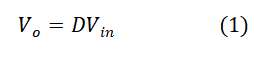
Under ideal operating conditions, the average output voltage of a buck converter is proportional to the input voltage and the switch duty ratio. This relationship is expressed as
Where:
- Vo represents the regulated output voltage (V),
- Vin denotes the input supply voltage (V),
- D is the converter duty ratio, defined as the ratio of switch ON time to the total switching period.
Equation (1) illustrates that the output voltage can be regulated by varying the effective duty ratio. In the proposed Constant On-Time controller, however, the duty ratio is not generated directly. Instead, the controller fixes the ON duration while allowing the OFF duration to vary dynamically. Consequently, the effective duty cycle changes automatically according to operating conditions, providing rapid transient response without requiring conventional PWM modulation [18].
Unlike fixed-frequency converters, the switching frequency of a Constant On-Time converter varies with load current and input voltage. Under heavy loading conditions, the converter switches more frequently because the OFF interval becomes shorter. Conversely, under light-load operation, the OFF duration increases, resulting in a lower switching frequency. This adaptive behavior improves dynamic performance while reducing unnecessary switching losses.
B. Overall Control Architecture
The proposed control strategy employs a dual-loop feedback architecture that combines voltage regulation with current-based switching control. The overall controller consists of two coordinated subsystems:
- An outer voltage regulation loop.
- An inner Constant On-Time current controller.
The outer control loop continuously monitors the converter output voltage and compares it with a predefined reference voltage. Any difference between the measured output voltage and the reference generates a voltage error signal. This error is processed through a proportional-integral (PI) controller to produce an appropriate reference current for the inductor.
The inner control loop compares the measured inductor current with the reference current produced by the PI controller. Whenever the measured current falls below the desired reference, the state machine immediately initiates a new switching cycle by turning the MOSFET ON for a fixed duration. This hierarchical control strategy separates slow voltage regulation from fast switching control, thereby improving converter stability and transient performance [19].
The proposed architecture closely resembles practical digital power converter implementations, where supervisory voltage regulation and fast current control are executed independently. Such separation simplifies controller tuning while allowing each control loop to operate according to its respective dynamic requirements.
You can download the Project files here: Download files now. (You must be logged in).
C. PI Voltage Controller
The primary objective of the outer voltage loop is to maintain a constant output voltage despite changes in load resistance or input supply voltage. A proportional-integral (PI) controller is selected because of its simple implementation, excellent steady-state accuracy, and widespread industrial acceptance [20].
The proportional component generates an output proportional to the instantaneous voltage error, providing immediate corrective action whenever the output voltage deviates from its reference value. Meanwhile, the integral component accumulates the error over time, gradually eliminating any steady-state offset that may remain after proportional correction.
The PI controller generates the desired inductor reference current according to

Where:
- I_ref(t) is the reference inductor current generated by the voltage controller (A),
- Kp is the proportional gain,
- Ki is the integral gain,
- e(t) is the voltage error signal,
- t represents time (s).
The voltage error signal is defined as the difference between the desired reference voltage and the measured converter output voltage. The proportional gain determines the controller’s immediate response to disturbances, whereas the integral gain removes accumulated steady-state errors and improves long-term regulation accuracy.
Appropriate selection of the PI gains significantly influences converter performance. Excessively high proportional gain may produce oscillatory behavior, while insufficient gain results in sluggish transient response. Similarly, improper integral gain selection may cause excessive overshoot or prolonged settling time. Therefore, the controller parameters should be carefully adjusted to achieve an optimal compromise between stability, response speed, and output voltage regulation [21].
Within the proposed PLECS implementation, the PI controller continuously updates the reference current supplied to the inner Constant On-Time controller. Since the current loop operates much faster than the voltage loop, the converter is capable of responding rapidly to dynamic load disturbances while maintaining excellent voltage regulation.
D. Constant On-Time Control Strategy
Unlike conventional PWM controllers that generate switching pulses using a periodic carrier waveform, the Constant On-Time controller operates as an event-driven switching algorithm. The controller continuously monitors the inductor current error and initiates switching actions only when predetermined operating conditions are satisfied.
The defining characteristic of Constant On-Time control is that every switching pulse has an identical ON duration regardless of converter operating conditions. Instead of varying pulse width, the controller adjusts the OFF interval to regulate converter output voltage. Consequently, the switching frequency automatically adapts to load demand without requiring additional frequency-control mechanisms [22].
When the measured inductor current becomes smaller than the reference current generated by the PI controller, the controller immediately activates the MOSFET. The switch remains ON for the predefined constant duration, denoted by (t_{on}). After completion of the ON interval, the MOSFET is turned OFF and remains OFF for at least the specified minimum OFF time, denoted by (t_{off,min}).
Following expiration of the minimum OFF interval, the controller evaluates the current error once again. If the inductor current is still below the desired reference, another ON interval begins immediately. Otherwise, the controller waits until the current error becomes positive before initiating the next switching cycle.
This event-driven operation provides several important advantages over fixed-frequency PWM control:
- Extremely fast transient response because switching begins immediately when required.
- Simplified digital implementation due to elimination of carrier waveform generation.
- Reduced computational complexity.
- Naturally adaptive switching frequency.
- Improved load regulation under rapidly changing operating conditions.
Because switching decisions depend directly on converter operating conditions rather than periodic timing signals, Constant On-Time control is particularly well suited for modern digitally controlled power converters implemented using microcontrollers, DSPs, or FPGA platforms [23].
E. State Machine-Based Digital Controller
One of the most distinctive features of the proposed converter is the implementation of the Constant On-Time controller using the PLECS State Machine block. Rather than constructing the controller from numerous logical gates and timing blocks, the entire switching algorithm is represented using a finite-state machine composed of three operating states: ON, OFF, and ReadyForOn.
The ON state corresponds to the active conduction interval of the power MOSFET. Upon entering this state, the switching signal is immediately assigned a logic-high value, thereby turning the MOSFET ON. Simultaneously, an internal timer begins counting the predefined constant ON duration. When this timer expires, the controller automatically transitions to the OFF state.
Within the OFF state, the switching signal is forced LOW, disconnecting the input source from the inductor. A second timer enforces the minimum OFF interval, preventing premature switching and ensuring proper converter operation. After the minimum OFF duration has elapsed, the controller evaluates the inductor current error.
If the measured current remains below the reference current, the controller immediately returns to the ON state, initiating another switching cycle. Otherwise, the controller enters the ReadyForOn state.
The ReadyForOn state represents an idle monitoring condition in which the controller continuously observes the current error without initiating switching. Once the current error becomes positive, indicating that additional energy must be supplied to the load, the controller instantly returns to the ON state and begins a new switching cycle.
This finite-state representation closely resembles the structure of embedded firmware executed in practical digital controllers. Consequently, the developed PLECS model serves not only as a simulation environment but also as a valuable prototype for future implementation using microcontrollers or digital signal processors.
IV. PLECS Model Development and Simulation Methodology
A. PLECS Model Development
The proposed buck converter was modeled using the PLECS simulation environment to evaluate the effectiveness of the State Machine-based Constant On-Time (COT) control strategy. PLECS provides an integrated platform for modeling power electronic converters, passive components, semiconductor devices, and digital control systems within a single simulation framework. Its event-driven simulation capability makes it particularly suitable for switching converter analysis where accurate representation of switching transitions and controller timing is essential [24].
The developed simulation model consists of two major sections: the power stage and the control stage. The power stage includes the DC input voltage source, power MOSFET, freewheeling diode, output inductor, output capacitor, and resistive load. These components collectively perform the voltage step-down operation while storing and transferring energy between the source and the load.
The control stage incorporates the dual-loop controller developed in this work. The outer voltage regulation loop continuously compares the measured output voltage with the reference voltage. The resulting voltage error is processed using a PI controller to generate the desired reference current. This current reference is subsequently provided to the inner Constant On-Time controller, which determines the switching sequence of the MOSFET.
Unlike conventional PWM implementations that require carrier generators and comparator circuits, the proposed controller relies entirely on the PLECS State Machine block. Internal timing events control the switching duration while logical conditions determine the transitions between different operating states. Consequently, the complete controller can be represented using only a small number of functional blocks, significantly improving model readability and simplifying future modifications.
Simulation scopes were connected to the output voltage, inductor current, current error, and gate switching signal to observe the converter performance under steady-state operating conditions. The animation capability of the State Machine block was also employed to visualize controller execution and state transitions during simulation.
B. Controller Implementation Using the State Machine Block
The Constant On-Time controller was implemented using the State Machine editor available within PLECS. This implementation accurately reproduces the behavior of a practical embedded controller by defining discrete operating states together with event-driven transitions.
Three operating states were created:
1) ON State
The ON state represents the conduction interval of the MOSFET. Upon entering this state, the controller immediately sets the switching signal to logic HIGH, thereby connecting the input source to the converter inductor. An internal timer simultaneously begins counting the predefined constant ON duration. After expiration of the timer event, the controller automatically exits the ON state and enters the OFF state.
2) OFF State
During the OFF state, the switching signal is forced LOW, disconnecting the input voltage from the converter. Energy previously stored in the inductor continues to supply the load through the freewheeling diode. Another timer guarantees that the switch remains OFF for at least the specified minimum OFF interval before another switching decision is permitted.
3) ReadyForOn State
The ReadyForOn state functions as an intermediate waiting condition. After completion of the minimum OFF interval, the controller checks the current error. If the measured current is still below the reference current, the controller immediately returns to the ON state. Otherwise, it enters the ReadyForOn state and continuously monitors the current error until another switching cycle becomes necessary.
The transition conditions defined within the State Machine ensure deterministic controller behavior while preventing unwanted switching events. The graphical representation also provides an intuitive understanding of controller operation, making debugging considerably easier than conventional logic-based implementations.
V. Simulation Results and Discussion
The developed converter model was simulated using PLECS to verify the effectiveness of the proposed Constant On-Time control strategy. Particular emphasis was placed on evaluating voltage regulation, inductor current behavior, switching operation, and state-machine execution.
The simulation demonstrates that the proposed controller successfully regulates the converter output while maintaining stable switching operation throughout the simulation interval.
A. Overall Converter Model
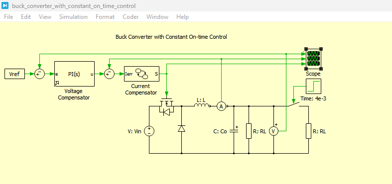
Figure 1: Buck Converter with constant On-time Control Model in PLECS
You can download the Project files here: Download files now. (You must be logged in).
Figure 1 illustrates the complete buck converter model developed in PLECS. The model integrates the power stage and the dual-loop controller into a unified simulation environment. The arrangement clearly demonstrates the interaction between the PI voltage controller, the current compensator, and the Constant On-Time state machine responsible for generating the MOSFET gate signal.
B. PI Voltage Controller
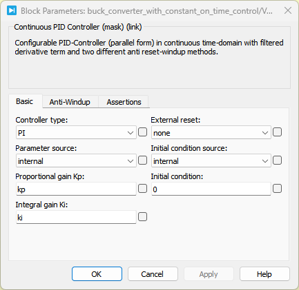
Figure 2: PI controller with its block parameters used in implementing of buck converter using PLECS
Figure 2 presents the implementation of the outer-loop PI voltage controller. The controller continuously compares the measured output voltage with the desired reference voltage and generates the appropriate reference current. The proportional component provides rapid response to voltage disturbances, whereas the integral component eliminates steady-state regulation error, thereby ensuring accurate output voltage control.
C. Current Compensator and State Machine-Based Constant On-Time Controller
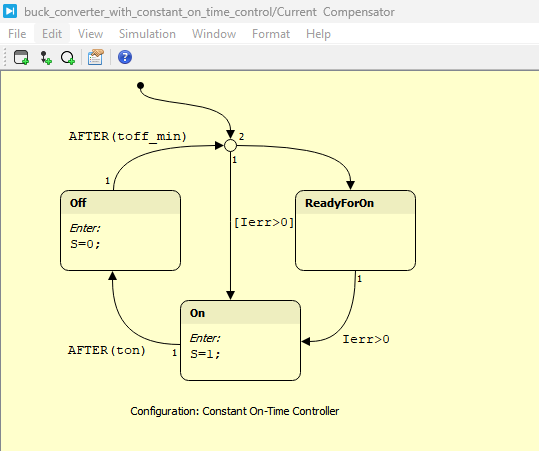
Figure 3: Current Compensator and State Machine-Based Constant On-Time Controller
Figure 3 presents the implementation of the inner control system of the proposed buck converter, comprising both the Current Compensator and the State Machine-based Constant On-Time (COT) controller developed in PLECS. The Current Compensator continuously compares the measured inductor current with the reference current generated by the outer PI voltage controller to produce the current error signal required for switching decisions. This error signal serves as the input to the State Machine controller, which consists of three operating states—ON, OFF, and ReadyForOn—connected through event-driven transitions. Internal timer events enforce the predefined constant ON time and minimum OFF time, while logical conditions based on the current error determine the transitions between states and the generation of the MOSFET gate signal. Compared with conventional logic-based implementations, the State Machine approach offers a more structured, modular, and intuitive controller design, enabling easier debugging, visualization of state transitions, and verification of switching behavior within the PLECS simulation environment. This integrated implementation accurately emulates the operation of a practical digitally controlled Constant On-Time converter and demonstrates the effectiveness of event-driven control for achieving fast dynamic response and reliable voltage regulation.
D. Output Voltage Response, Inductor Current Waveform and Gate Switching Signal
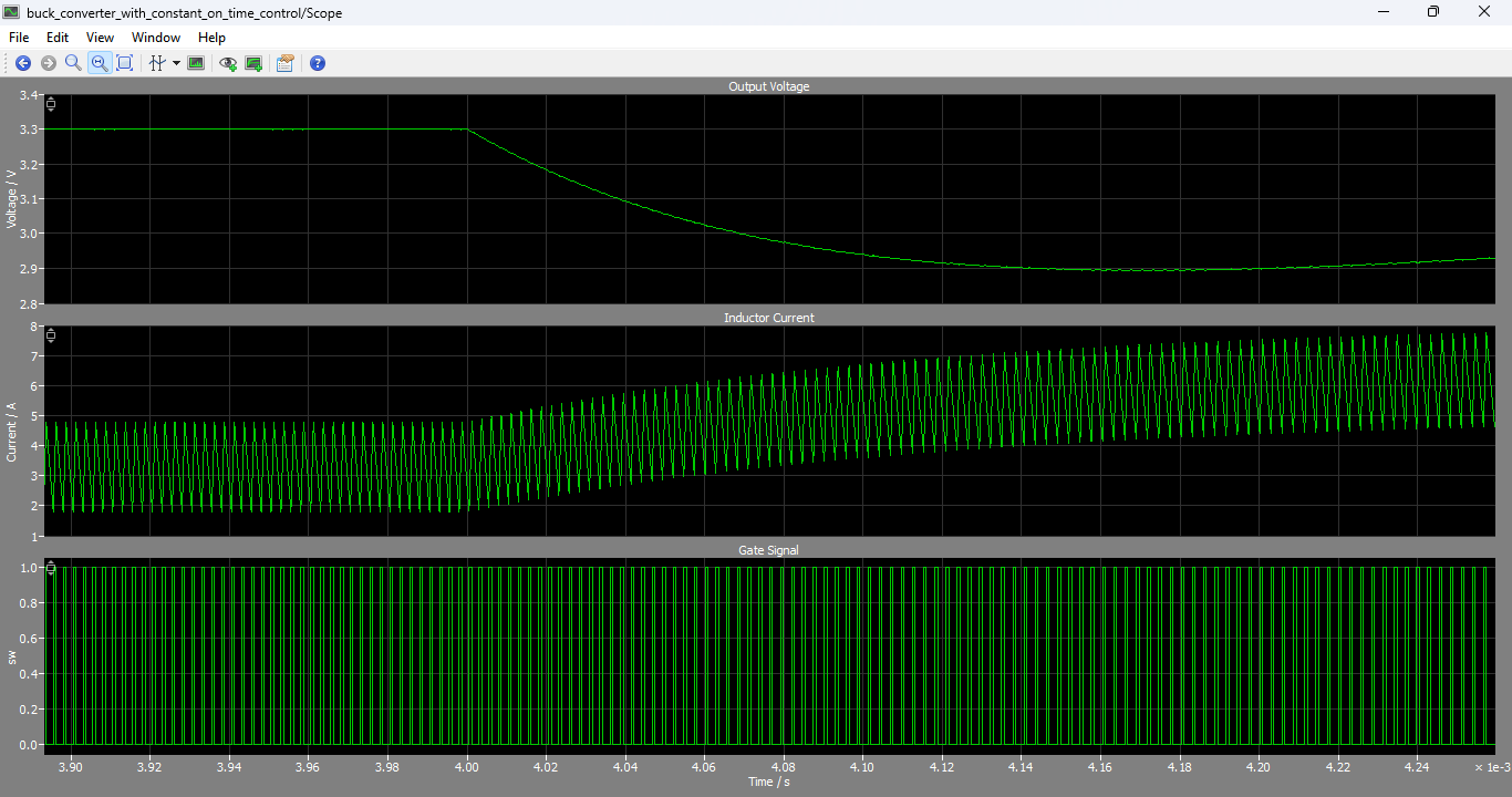
Figure 4: Output voltage, inductor current, and MOSFET gate switching signal waveforms of the proposed Constant On-Time controlled buck converter.
You can download the Project files here: Download files now. (You must be logged in).
Figure 4 presents the simulated output voltage, inductor current, and MOSFET gate switching signal of the proposed State Machine-based Constant On-Time (COT) controlled buck converter developed in PLECS. The output voltage waveform demonstrates that, following a short startup transient, the converter rapidly reaches the desired reference voltage with negligible steady-state error, minimal overshoot, and stable closed-loop operation, confirming the effectiveness of the outer PI voltage controller. The corresponding inductor current exhibits the expected triangular waveform produced by the periodic charging and discharging of the inductor, where the current increases during the constant ON interval and decreases during the OFF interval while continuously supplying energy to the load through the output filter. The average inductor current closely follows the reference generated by the PI controller, validating the proper operation of the inner current regulation loop. Additionally, the MOSFET gate switching signal confirms the successful implementation of the Constant On-Time control strategy, with each switching pulse maintaining a fixed ON duration while the OFF interval varies according to the converter operating conditions. This adaptive switching behavior enables rapid response to load variations, efficient energy transfer, and reliable output voltage regulation, demonstrating the effectiveness of the proposed event-driven State Machine controller for digitally controlled buck converter applications.
E. Controller Performance Evaluation
Simulation results indicate that the proposed controller successfully achieves the primary objectives established during system design. The converter maintains stable output voltage while the current controller rapidly responds to changing operating conditions. The event-driven implementation eliminates unnecessary switching delays and provides fast corrective action whenever the inductor current falls below the reference value.
The State Machine implementation also demonstrates several practical advantages for digital controller development. Since controller behavior is explicitly represented through operating states and transition conditions, debugging becomes substantially easier compared with conventional logic circuits. Furthermore, the state-machine approach closely resembles firmware implementation used in embedded digital controllers, facilitating future hardware realization using microcontrollers or digital signal processors.
Overall, the simulation results verify that the proposed PLECS implementation provides an effective and practical solution for Constant On-Time control of buck converters.
VI. Advantages and Limitations
The proposed controller offers several significant advantages over conventional PWM-based implementations. First, the Constant On-Time strategy provides exceptionally fast transient response because switching actions are initiated immediately when current demand increases. Second, the State Machine implementation simplifies controller development by replacing complex timing logic with intuitive state-based operation. Third, the controller is highly suitable for digital implementation because its operation closely resembles embedded software executed by modern microcontrollers.
Despite these advantages, several practical limitations should also be considered. Since the switching frequency varies with operating conditions, electromagnetic interference (EMI) filtering may become more challenging compared with fixed-frequency PWM converters. In addition, controller parameter selection, including PI gains and timing constants, requires careful tuning to ensure stable operation across the complete operating range.
VII. Conclusion
This paper presented the design and simulation of a State Machine-based Constant On-Time controlled buck converter using the PLECS simulation environment. The proposed controller combines an outer proportional-integral voltage regulator with an inner event-driven current controller implemented using a finite-state machine. Unlike conventional PWM techniques, the proposed controller maintains a constant switch ON duration while dynamically adjusting the OFF interval according to converter operating conditions.
The developed simulation model successfully demonstrated stable converter operation, accurate voltage regulation, adaptive switching frequency, and rapid transient response. The finite-state implementation consisting of the ON, OFF, and ReadyForOn states provided a clear and intuitive representation of the switching algorithm while simplifying controller development and verification.
Simulation waveforms confirmed that the PI controller effectively regulated the output voltage, whereas the Constant On-Time controller accurately generated switching signals according to current demand. The graphical State Machine implementation also proved highly suitable for model-based digital controller development because it closely resembles practical embedded firmware implementation.
Overall, the proposed methodology demonstrates that State Machine-based Constant On-Time control provides an efficient, flexible, and reliable solution for digitally controlled buck converters and serves as an excellent platform for future embedded power electronics research.
VIII. Future Work
Future work may extend the proposed controller by implementing the developed algorithm on real-time embedded hardware such as Texas Instruments C2000 microcontrollers or FPGA-based digital control platforms. Adaptive PI parameter tuning, predictive current control, artificial intelligence-based optimization, and fault-tolerant switching strategies may also be investigated to further improve converter performance under rapidly changing operating conditions. Additionally, experimental validation using a laboratory hardware prototype will provide further verification of the simulation results presented in this work.
References
[1] R. W. Erickson and D. Maksimović, Fundamentals of Power Electronics, 3rd ed. New York, NY, USA: Springer, 2020.
[2] N. Mohan, T. M. Undeland, and W. P. Robbins, Power Electronics: Converters, Applications and Design, 3rd ed. Hoboken, NJ, USA: Wiley, 2003.
[3] D. G. Holmes and T. A. Lipo, Pulse Width Modulation for Power Converters. Hoboken, NJ, USA: Wiley, 2003.
[4] R. Redl and N. O. Sokal, “Near-optimum dynamic regulation of DC-DC converters,” IEEE Transactions on Power Electronics, vol. 1, no. 4, pp. 225–236, Oct. 1986.
[5] R. D. Middlebrook and S. Ćuk, “A general unified approach to modelling switching-converter power stages,” IEEE Power Electronics Specialists Conference, 1976.
[6] C. P. Basso, Switch-Mode Power Supplies: SPICE Simulations and Practical Designs. McGraw-Hill, 2014.
[7] M. K. Kazimierczuk, Pulse Width Modulated DC-DC Power Converters. Wiley, 2016.
[8] Plexim GmbH, PLECS User Manual, Zurich, Switzerland, 2023.
[9] Plexim GmbH, “Buck Converter with Constant On-Time Control,” PLECS Demo Models Documentation, Version 4.4.2, 2023.
[10] R. W. Erickson, “Modeling and design of switching regulators,” IEEE Transactions on Aerospace and Electronic Systems, vol. AES-15, no. 2, pp. 271–283, 1979.
[11] P. T. Krein, Elements of Power Electronics. Oxford University Press, 2015.
[12] A. Pressman, K. Billings, and T. Morey, Switching Power Supply Design, 3rd ed. McGraw-Hill, 2009.
[13] M. H. Rashid, Power Electronics Handbook, 4th ed. Butterworth-Heinemann, 2018.
[14] F. C. Lee and P. Mattavelli, “Modeling and control of switching converters,” IEEE Transactions on Industrial Electronics, vol. 58, no. 4, pp. 1258–1270, Apr. 2011.
[15] B. Bryant and M. K. Kazimierczuk, “Voltage-loop power-stage transfer functions for PWM DC–DC converters,” IEEE Transactions on Industrial Electronics, vol. 54, no. 2, pp. 1307–1312, Apr. 2007.
You can download the Project files here: Download files now. (You must be logged in).







Responses