

Horsepower vs Torque Calculator: Gearing and Wheel Force
Explore hp vs torque with editable dyno points, six-speed gearing, wheel force and road loads. Compare a high-torque engine with a high-revving engine at the same speed.

Compare horsepower, crank torque and wheel force without confusing three different quantities. This hp vs torque explorer is for engineering students, vehicle builders and anyone trying to understand why an engine with a smaller torque rating can still accelerate harder at a particular road speed.
Start with the default teaching curves. Engine A produces more crank torque and reaches its usable speed limit sooner. Engine B produces less torque but keeps working at higher rpm. These are deliberately illustrative inputs, not measured specifications for named vehicles. Enable Edit the two five-point torque curves to enter your own ordered rpm and full-load crank-torque points. Turning that option off restores the teaching defaults for the calculation. The point tables show the corresponding power, and straight interpolation joins adjacent torque points.
Set a road speed, six transmission ratios, each engine's final drive and the effective rolling tyre diameter. Both comparison cars share the same mass, tyre size, efficiency and road load. The tool examines every gear that keeps the engine between its first and last rpm points, then selects the gear with the greatest wheel force. Change the final drive to see how shorter gearing trades road speed for torque multiplication.
Read the torque and power plots together. Power is torque multiplied by angular speed, so maintaining torque at higher rpm increases power. In the wheel torque calculator, the gearbox and final drive multiply torque while reducing rotational speed. At a fixed road speed, wheel force equals delivered power divided by speed. More available wheel power at that operating point therefore gives more acceleration when mass and resistance are equal. A peak horsepower rating alone does not guarantee a win: the available ratios must let the engine reach a useful part of its curve.
The force charts leave gaps outside each curve's entered rpm range. The envelope compares the strongest available gear with aerodynamic drag plus rolling resistance. A negative instantaneous acceleration means road load exceeds drive force. No traction cap is applied.
Use the separate horsepower to torque calculator for one operating point, in either direction. Mechanical horsepower is about 745.7 W; metric PS is different. Numerical horsepower and lb-ft cross at approximately 5,252 rpm only when they share the same numerical scale. That crossover is a unit-conversion result, not an engine event. The dedicated crossover plot intentionally retains those fixed numerical units.
Press play to rotate the wheels and crank markers at one-fortieth real time. The two cars stay aligned at the selected speed. The human stair-climbing example and one-horsepower horse benchmark provide scale; their durations are different.
This explorer explains operating points. It excludes launches, shifting delays, rotating inertia, tyre slip, gradients and complete elapsed-time predictions. For full runs, the companion is the Quarter-Mile and 0–60 Simulator once it is available in the catalog.
How it is calculated
The calculation uses full-load crankshaft torque points. Linear interpolation gives only between the first and last entered rpm points. No torque or power is extrapolated outside that interval. Derived power is
The formulas use explicit unit conversions rather than a hidden rpm factor. OpenStax, University Physics 1 §10.8 gives the rotational power relation. NIST SP 811 gives mechanical horsepower as approximately 745.7 W; this is not metric horsepower (PS, approximately 735.5 W).
For gearbox ratio and final drive , the no-slip kinematics and wheel force are
Wheel torque is the sum at the driven tyres, not the torque at a single halfshaft. The tool checks all six discrete gears and chooses the greatest feasible wheel force at the selected speed. A tie selects the first eligible gear. It does not predict a shift schedule.
Road load follows NASA's drag equation and the constant rolling-coefficient model documented by MathWorks:
Here is the drag coefficient times frontal area, and . With no slip, . This identity explains why more power available at the wheels at the same speed, rather than a larger crank-torque rating by itself, gives greater acceleration for otherwise equal cars.
The peak-power table samples each interpolated curve at 241 equally spaced rpm values. The exact peak can lie between samples. The crossover plot shows the dimensionless ratios and on one numerical scale; their nonzero intersection occurs at approximately 5,252.1 rpm. It intentionally keeps those units even when physical result cards and charts use metric display.
Holley's Hot Rod Calc guide provides independent worked checks: attached PDF p.50 (printed p.48) for both converter directions, p.43 for road speed, and p.44 for cruising rpm. Tolerances allow the guide's three-decimal rounding. OpenStax Example 10.19 independently checks the inverse relation. Short quotes in the verification cases identify the published results.
Animation uses closed-form wheel and crank angles from the current speed and selected gear. Time affects only those angles, scrolling road marks and the schematic; dyno sweeps and gear selection do not depend on animation time.
The dyno plotting axis is the sorted union of both engines' individual sampling grids and all entered rpm points. Each engine retains its own samples even when its usable rpm interval is very narrow. Values outside its entered interval remain explicit chart gaps.
Assumptions
- Engine A and B defaults are author-designed teaching curves. They are editable inputs, not measured dyno data or manufacturer claims.
- All entered torques refer to the crankshaft under full load. A chassis-dyno trace requires a separate, justified conversion before use.
- Both cars have identical mass, tyre diameter, constant drivetrain efficiency, drag area and rolling coefficient; only the entered engine curves and final drives differ.
- Rigid, no-slip gearing; fixed effective rolling radius; still air; level road; constant air density and rolling coefficient. Vehicle speed is positive.
- Translational mass only: wheel, shaft, flywheel and engine rotational inertia are omitted. No tyre traction limit, load transfer, turbo lag, clutch slip, torque converter, rev-limiter dynamics, gearshift loss or accessory-load map.
- The five entered rpm points delimit the usable range. Gaps mean unavailable rpm data, not zero measured engine torque.
- The 538 W human scale is OpenStax College Physics 2e Example 7.11, a brief stair-running example. The one-horsepower horse benchmark follows that text's sustained-work comparison and is a scale reference, not a fixed maximum power for every horse. Donut's video illustrates why actual horse output and test duration matter.
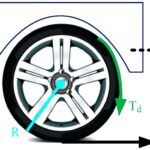
- Drawings are schematic; force arrows share a normalized scale and the drawing's speed annotation is in km/h. Wheels and crank markers move at 1/40 real time. Animation never integrates an acceleration history.
Where it applies
Use this for teaching, dimensional checks and preliminary comparisons of full-load torque curves. Enter five strictly increasing rpm values for each engine and positive, descending transmission ratios. At least one positive torque point and at least one usable gear at the selected speed are required for each engine. Adjust the speed, final drive, ratios or curve endpoints when the input message says no gear is available.
The single-point converter and gearing probe are independent of the dyno curves. The probe uses engine A's final drive; its reported speed may exceed the usable engine range because it is a kinematic conversion, not a speed prediction.
The force envelope is an instantaneous, traction-unlimited result. It cannot establish launch performance, safe vehicle speed, passing distance, quarter-mile elapsed time or a real shift strategy. A force curve above road load indicates positive acceleration only under the stated assumptions. A sampled peak-power rating can miss a narrow peak, especially with irregularly spaced user points.
The normal metric/US controls convert physical inputs, result cards, tables and chart axes. The crossover plot is deliberately dimensionless and labelled in fixed numerical hp/lb-ft units. It must not be interpreted as equality between physical torque and power.
Full-run simulations belong in the separate Quarter-Mile and 0–60 Simulator. That companion is not currently available in the catalog. This explorer does not predict complete runs.
The crossover is visible only when engine B's entered rpm interval contains approximately 5,252 rpm and torque there is nonzero. Changing a curve does not preserve the default engine's high-torque or high-revving character.
References
- [OpenStax, University Physics Volume 1, §10.8, rotational power and Example 10.19](https://openstax.org/books/university-physics-volume-1/pages/10-8-work-and-power-for-rotational-motion).
- [Holley / Calculated Industries, Hot Rod Calc User Guide, PDF pp.43–44 and 49–50](https://documents.holley.com/mr_gasket_instructions_hot_rod_calculator_8703.pdf). Attached as s1; source of independent torque, power and gearing examples.
- [NIST SP 811, Appendix B.9, power conversion factors](https://www.nist.gov/pml/special-publication-811/nist-guide-si-appendix-b-conversion-factors/nist-guide-si-appendix-b9). Mechanical hp and metric horsepower differ.
- [NASA Glenn Research Center, The Drag Equation](https://www.grc.nasa.gov/www/k-12/VirtualAero/BottleRocket/airplane/drageq.html).
- [MathWorks Simscape Driveline, Longitudinal Vehicle](https://www.mathworks.com/help/sdl/ref/longitudinalvehicle.html). Regular parameter set: tyre rolling force C_R m g and aerodynamic road load.
- [OpenStax, College Physics 2e, §7.7, Example 7.11](https://openstax.org/books/college-physics-2e/pages/7-7-power). Human stair-running mechanical power: 538 W; sustained horse comparison for scale.
- [The Maker, Horsepower vs Torque Simplest Explanation (2021)](https://www.youtube.com/watch?v=NkIO08dlg_s). Conceptual background only; this tool uses its own wording, figures and engine inputs.
- [Donut, How Much Horsepower is a Horse? (2023)](https://www.youtube.com/watch?v=7qxTKtlvaVE). Background on actual animal/human dynamometer comparisons; no unverified peak number from the video is used.
Inputs
| Input | Symbol | Unit | Default |
|---|---|---|---|
| Edit the two five-point torque curves Defaults are illustrative teaching curves, not measurements of production engines. Enable this to enter your own ordered rpm and crank-torque points. | edit_curves | false | |
| Compare at road speed Both cars are evaluated at this same speed. Best gear means maximum available wheel force, within the entered curve's rpm range. | v_road | km/h | 100 |
| Animation time Play wheel rotation and road motion at 1/40 real time. Cars stay aligned at the selected speed; no race or acceleration history is integrated. | t_anim | s | 1.4 |
| Point 1: engine speed Enter speeds in strictly increasing order. Point 1 is the lowest usable speed; point 5 is the upper usable limit. | nA_1 | rpm | 1000 |
| Point 1: crank torque Full-load crankshaft torque at the adjacent rpm. Linear interpolation joins the five points. Do not mix wheel-dyno torque with crank torque. | TA_1 | N*m | 220 |
| Point 2: engine speed Enter speeds in strictly increasing order. Point 1 is the lowest usable speed; point 5 is the upper usable limit. | nA_2 | rpm | 2000 |
| Point 2: crank torque Full-load crankshaft torque at the adjacent rpm. Linear interpolation joins the five points. Do not mix wheel-dyno torque with crank torque. | TA_2 | N*m | 400 |
| Point 3: engine speed Enter speeds in strictly increasing order. Point 1 is the lowest usable speed; point 5 is the upper usable limit. | nA_3 | rpm | 3000 |
| Point 3: crank torque Full-load crankshaft torque at the adjacent rpm. Linear interpolation joins the five points. Do not mix wheel-dyno torque with crank torque. | TA_3 | N*m | 400 |
| Point 4: engine speed Enter speeds in strictly increasing order. Point 1 is the lowest usable speed; point 5 is the upper usable limit. | nA_4 | rpm | 4000 |
| Point 4: crank torque Full-load crankshaft torque at the adjacent rpm. Linear interpolation joins the five points. Do not mix wheel-dyno torque with crank torque. | TA_4 | N*m | 330 |
| Point 5: engine speed Enter speeds in strictly increasing order. Point 1 is the lowest usable speed; point 5 is the upper usable limit. | nA_5 | rpm | 5000 |
| Point 5: crank torque Full-load crankshaft torque at the adjacent rpm. Linear interpolation joins the five points. Do not mix wheel-dyno torque with crank torque. | TA_5 | N*m | 250 |
| Point 1: engine speed Enter speeds in strictly increasing order. Point 1 is the lowest usable speed; point 5 is the upper usable limit. | nB_1 | rpm | 1000 |
| Point 1: crank torque Full-load crankshaft torque at the adjacent rpm. Linear interpolation joins the five points. Do not mix wheel-dyno torque with crank torque. | TB_1 | N*m | 110 |
| Point 2: engine speed Enter speeds in strictly increasing order. Point 1 is the lowest usable speed; point 5 is the upper usable limit. | nB_2 | rpm | 2750 |
| Point 2: crank torque Full-load crankshaft torque at the adjacent rpm. Linear interpolation joins the five points. Do not mix wheel-dyno torque with crank torque. | TB_2 | N*m | 170 |
| Point 3: engine speed Enter speeds in strictly increasing order. Point 1 is the lowest usable speed; point 5 is the upper usable limit. | nB_3 | rpm | 4500 |
| Point 3: crank torque Full-load crankshaft torque at the adjacent rpm. Linear interpolation joins the five points. Do not mix wheel-dyno torque with crank torque. | TB_3 | N*m | 200 |
| Point 4: engine speed Enter speeds in strictly increasing order. Point 1 is the lowest usable speed; point 5 is the upper usable limit. | nB_4 | rpm | 6250 |
| Point 4: crank torque Full-load crankshaft torque at the adjacent rpm. Linear interpolation joins the five points. Do not mix wheel-dyno torque with crank torque. | TB_4 | N*m | 230 |
| Point 5: engine speed Enter speeds in strictly increasing order. Point 1 is the lowest usable speed; point 5 is the upper usable limit. | nB_5 | rpm | 8000 |
| Point 5: crank torque Full-load crankshaft torque at the adjacent rpm. Linear interpolation joins the five points. Do not mix wheel-dyno torque with crank torque. | TB_5 | N*m | 200 |
| Gear 1 ratio Engine speed divided by gearbox output speed. Ratios must decrease from first through sixth. | g_1 | 3.5 | |
| Gear 2 ratio Engine speed divided by gearbox output speed. Ratios must decrease from first through sixth. | g_2 | 2.1 | |
| Gear 3 ratio Engine speed divided by gearbox output speed. Ratios must decrease from first through sixth. | g_3 | 1.4 | |
| Gear 4 ratio Engine speed divided by gearbox output speed. Ratios must decrease from first through sixth. | g_4 | 1 | |
| Gear 5 ratio Engine speed divided by gearbox output speed. Ratios must decrease from first through sixth. | g_5 | 0.82 | |
| Gear 6 ratio Engine speed divided by gearbox output speed. Ratios must decrease from first through sixth. | g_6 | 0.68 | |
| Final drive: engine A | final_A | 3.7 | |
| Final drive: engine B Increase this to demonstrate how a higher-revving engine can use shorter gearing at the same road speed. | final_B | 3.7 | |
| Drivetrain efficiency Fraction of crank power delivered to the tyres; 0.90 means 90%. | eta | 0.9 | |
| Effective rolling tyre diameter Use twice the effective rolling radius. The nominal unloaded diameter is an approximation. | d_tyre | m | 0.64 |
| Mass of each comparison car | m_car | kg | 1400 |
| Drag coefficient × frontal area CdA combines the dimensionless drag coefficient and frontal area. Still air and a level road are assumed. | CdA | m^2 | 0.66 |
| Air density | rho_air | kg/m^3 | 1.225 |
| Rolling resistance coefficient | C_rr | 0.012 | |
| Single-point converter: solve for | calc_mode | Power from torque and rpm | |
| Converter / gearing probe engine speed | n_entry | rpm | 4000 |
| Converter crank torque | T_entry | N*m | 300 |
| Converter crank power Use the unit control to enter mechanical hp. Metric PS is a different unit; 1 PS = 735.49875 W. | P_entry | kW | 100 |
| Gearing probe: gear number Uses engine A's final drive. Its speed/rpm outputs are purely kinematic and are independent of the dyno curve. | gear_probe | 3 |
Results
With the default inputs above, the calc gives:
| Result | Value |
|---|---|
| A: wheel force in best gear | 4,465 N |
| B: wheel force in best gear | 4,955 N |
| A: instantaneous acceleration | 2.85 m/s² |
| B: instantaneous acceleration | 3.2 m/s² |
| Converter: mechanical horsepower | 168.52 hp |
| Converter: crank torque | 300 N·m |
| Numerical hp / lb-ft crossover | 5,252.1 1/min |
Checked against sources
Each case below was calculated by this calc and agrees with the value from its source (within the tolerance where one is shown).
Holley: 445 lb-ft at 3,800 rpm
Source: Holley Hot Rod Calc User Guide, attached PDF p.50 (printed p.48): 445 lb-ft at 3,800 rpm gives 321.966 mechanical hp. Torque entered in N m using the exact international foot and pound-force.
Inputs: Converter crank torque = 603.3 N·m; Converter / gearing probe engine speed = 3,800 rpm; the others as above.
| Result | Source | This calc |
|---|---|---|
| Converter: mechanical horsepower | 322 hp | 322 hp |
Holley: 366 hp at 5,400 rpm
Source: Holley Hot Rod Calc User Guide, attached PDF p.50 (printed p.48): 366 mechanical hp at 5,400 rpm gives 355.977 lb-ft. Power entered in kW.
Inputs: Single-point converter: solve for = Torque from power and rpm; Converter crank power = 272.9 kW; Converter / gearing probe engine speed = 5,400 rpm; the others as above.
| Result | Source | This calc |
|---|---|---|
| Single-point crank torque in lb-ft | 356 lbf·ft | 356 lbf·ft |
Holley: Mustang gearing and 26-inch tyre
Source: Holley guide attached PDF p.43 (printed p.41): 5,500 rpm, second gear 1.99, final drive 3.08 and 26-inch tyre gives 69.409 mph.
Inputs: Final drive: engine A = 3.08; Gear 2 ratio = 1.99; Effective rolling tyre diameter = 0.6604 m; Converter / gearing probe engine speed = 5,500 rpm; Gearing probe: gear number = 2; the others as above.
| Result | Source | This calc |
|---|---|---|
| Probe road speed in mph | 69.409 mph | 69.409 mph |
Holley: cruising at 65 mph in fifth
Source: Holley guide attached PDF p.44 (printed p.42): 65 mph, fifth gear 0.68, final drive 3.08 and 26-inch tyre gives 1,760.004 rpm. The sixth ratio is set to 0.60 solely to keep the six-speed comparison gearbox strictly descending; it is not part of the source's fifth-gear calculation.
Inputs: Final drive: engine A = 3.08; Gear 5 ratio = 0.68; Effective rolling tyre diameter = 0.6604 m; Compare at road speed = 104.6 km/h; Gearing probe: gear number = 5; Gear 6 ratio = 0.6; the others as above.
| Result | Source | This calc |
|---|---|---|
| Engine rpm at the chosen road speed | 1,760 rpm | 1,760 rpm |
OpenStax 10.19: 90 kW boat propeller at 300 rpm
Source: OpenStax University Physics 1, Example 10.19, https://openstax.org/books/university-physics-volume-1/pages/10-8-work-and-power-for-rotational-motion : a 90,000 W boat engine at 300 rev/min produces 2,864.8 N m. The displayed 31.4 rad/s is rounded; use the unrounded angular-speed conversion when reproducing the torque.
Inputs: Single-point converter: solve for = Torque from power and rpm; Converter crank power = 90 kW; Converter / gearing probe engine speed = 300 rpm; the others as above.
| Result | Source | This calc |
|---|---|---|
| Converter: crank torque | 2,865 N·m | 2,865 N·m |
MathWorks: typical small-car rolling road load
Source: MathWorks Longitudinal Vehicle, predefined Typical small car: 1,100 kg and C_R=0.013; the Road-load table gives A=140.3 N. The tool uses standard gravity 9.80665 m/s² instead of the documentation's default 9.81; the resulting 0.065 N difference is within the published 0.1 N rounding scale. https://www.mathworks.com/help/sdl/ref/longitudinalvehicle.html
Inputs: Mass of each comparison car = 1,100 kg; Rolling resistance coefficient = 0.013; the others as above.
| Result | Source | This calc |
|---|---|---|
| Rolling resistance on a level road | 140.3 N | 140.2 N |
Related Resources
Related articles
-
 Independent Torque Control for Zero-Turn Vehicles, Optimizing Maneuverability and Energy Efficiency Using Matlab
- Advanced Dragon Flight Dynamics, MATLAB-Based 6-DOF Simulation and Performance Evaluation
- Design and Simulation of a Lithium-Ion Battery Powered Power-Split Hybrid Electric Vehicle Using a Planetary Gear-Based Series–Parallel Architecture













Responses