

Design and Simulation of a Lithium-Ion Battery Powered Power-Split Hybrid Electric Vehicle Using a Planetary Gear-Based Series–Parallel Architecture

Autor: Waqas Javaid
Abstract
Hybrid Electric Vehicles (HEVs) have emerged as an effective solution for reducing fuel consumption, greenhouse gas emissions, and dependence on fossil fuels while maintaining vehicle performance. Among various HEV configurations, the power-split architecture combines the advantages of both series and parallel hybrid topologies by enabling flexible power flow between the internal combustion engine, electric machines, and energy storage system. This paper presents the modeling and simulation of a lithium-ion battery-powered power-split hybrid electric vehicle implemented in the PLECS simulation environment. The proposed system consists of a bidirectional DC/DC converter, lithium-ion battery pack, two permanent magnet synchronous machines (MG1 and MG2), a planetary gear set, and an engine operating according to a minimum brake specific fuel consumption strategy. The DC/DC converter regulates a 500 V DC bus, while MG1 and MG2 provide propulsion, power generation, and engine speed regulation. The planetary gear set enables efficient power sharing among the engine, generator, and traction motor. Simulation results demonstrate successful startup operation, engine speed regulation, wheel acceleration, DC bus voltage stabilization, and coordinated energy management. The developed model provides a comprehensive framework for studying power-split HEV dynamics and control strategies and can serve as a basis for future optimization and advanced energy management research.
I. Introduction
Growing concerns regarding environmental pollution, rising fuel prices, and increasingly stringent emission regulations have accelerated the development of hybrid and electric transportation technologies. Hybrid Electric Vehicles (HEVs) combine an internal combustion engine (ICE) with electric propulsion systems to achieve improved fuel economy and reduced emissions compared to conventional vehicles [2].
Among HEV configurations, series and parallel architectures represent two widely adopted approaches. Series hybrid systems allow the engine to operate independently from the wheels but suffer from multiple energy conversion stages. Parallel hybrid systems provide direct mechanical coupling between the engine and wheels but may not always operate the engine at its most efficient operating point. To overcome these limitations, power-split hybrid architectures have been developed, combining the benefits of both configurations through a planetary gear mechanism [2].
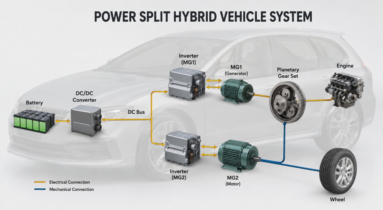
Figure 1: Proposed power-split hybrid electric vehicle (HEV) architecture consisting of a lithium-ion battery pack, bidirectional DC/DC converter, DC bus, dual motor-generator units (MG1 and MG2), planetary gear set, internal combustion engine, and wheel drive system. The diagram illustrates both electrical and mechanical power flow paths within the series-parallel hybrid drivetrain.
Figure 1 presents the overall architecture of the proposed power-split hybrid electric vehicle system modeled in PLECS. The system integrates a lithium-ion battery pack connected to a regulated 500 V DC bus through a bidirectional DC/DC converter. Two permanent magnet synchronous machines, namely MG1 and MG2, are interfaced with the DC bus via dedicated inverter drives. MG2 primarily operates as the traction motor to propel the vehicle, while MG1 functions as both a motor and generator for engine speed control and power generation. The internal combustion engine, MG1, and MG2 are mechanically coupled through a planetary gear set, enabling flexible power distribution between electrical and mechanical propulsion paths. This configuration combines the advantages of series and parallel hybrid architectures, allowing efficient energy management, improved fuel economy, and enhanced vehicle performance under varying operating conditions.
Power-split HEVs employ a planetary gear set (PGS) that mechanically couples the engine, generator, and traction motor. This arrangement enables flexible power distribution between mechanical and electrical paths, thereby improving fuel efficiency and overall vehicle performance. The architecture has been successfully utilized in commercial hybrid vehicles due to its capability to maintain engine operation near optimal efficiency conditions while satisfying vehicle propulsion requirements.
Another critical component of modern HEVs is the lithium-ion battery system. Lithium-ion batteries offer high energy density, high power capability, low self-discharge rate, and long cycle life, making them suitable for automotive applications. Accurate battery modeling is essential for predicting state-of-charge (SOC), voltage behavior, and overall energy management performance [1].
This paper investigates the design and simulation of a lithium-ion battery-powered power-split hybrid electric vehicle implemented in PLECS. The developed model integrates electrical, mechanical, and control subsystems to analyze startup and transient operating conditions. The objective is to evaluate system-level interactions among the battery, power electronics, electric machines, engine, and planetary gear set while maintaining stable DC bus voltage and desired speed references.
II. System Architecture
The proposed power-split HEV consists of the following major subsystems:
- Lithium-ion battery pack
- Bidirectional DC/DC converter
- DC bus
- Motor-generator unit MG1
- Traction motor MG2
- Internal combustion engine
- Planetary gear set
- Vehicle wheel and load model
- Digital control system
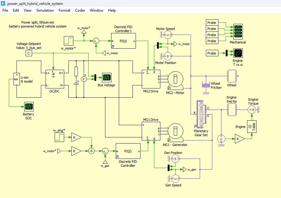
Figure 2: Power Split Hybrid vehicle system model development in PLECS Simulation
Figure 2 presents the complete power-split hybrid electric vehicle (HEV) system model developed in the PLECS simulation environment. The model integrates a lithium-ion battery, bidirectional DC/DC converter, DC bus, dual permanent magnet synchronous machines (MG1 and MG2), planetary gear set, internal combustion engine, and vehicle wheel dynamics. The architecture enables both electrical and mechanical power transfer, allowing efficient energy management and coordinated operation between the battery, electric machines, and engine for improved vehicle performance and fuel efficiency.
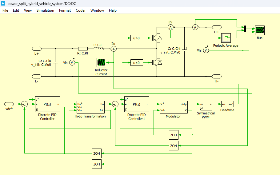
Figure 3: DC-DC Converter circuit design in PLECS
Figure 3 presents the bidirectional DC/DC converter circuit implemented in PLECS to interface the lithium-ion battery with the DC bus. The converter is responsible for regulating the DC bus voltage at the desired reference value while enabling bidirectional power flow between the battery and the electrical drive system. During acceleration, the converter supplies power from the battery to the DC bus, whereas during charging or regenerative operation, it transfers energy back to the battery, ensuring stable system operation.
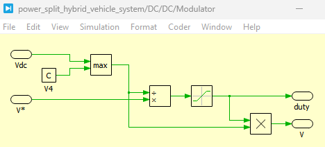
Figure 4: Modulator Circuit of Hybrid vehicle system in PLECS
Figure 4 presents the modulation circuit used in the hybrid vehicle system for generating gate pulses to control the power electronic switches of the converter and inverter systems. The modulator compares control signals with a carrier waveform to produce pulse-width modulation (PWM) signals, which regulate the switching behavior of the semiconductor devices. This modulation strategy enables precise control of voltage, current, and torque within the hybrid powertrain system.
The overall architecture forms an electrically and mechanically coupled hybrid propulsion system. The battery supplies electrical energy to the DC bus through the bidirectional converter. MG2 primarily functions as the traction motor, while MG1 serves as both a motor and generator depending on operating conditions. The planetary gear set provides mechanical coupling between the engine and electric machines.
The DC bus serves as the common energy distribution node connecting the battery and both electric drive systems. Through coordinated control, electrical energy can flow bidirectionally between the battery and electric machines, enabling propulsion assistance, regenerative operation, and engine speed regulation.
III. Lithium-Ion Battery Modeling
The battery subsystem is modeled using the resistor-only equivalent circuit model proposed by Tremblay and Dessaint [1]. This model provides a practical representation of lithium-ion battery behavior using information readily available from manufacturer datasheets.
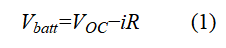
The battery voltage is represented as
where:
- Vbatt = terminal battery voltage (V)
- V_OC= open-circuit voltage (V)
- i = battery current (A)
- R = internal battery resistance (Ω)
Equation (1) represents the voltage drop across the internal resistance during charging and discharging processes. The open-circuit voltage is determined using lookup tables derived from battery state-of-charge characteristics [1].
The battery model includes SOC estimation and voltage calculations based on charge depletion. A low-pass filter is incorporated to improve numerical stability and represent battery dynamic behavior more realistically.
The simplicity of the resistor-only model enables efficient simulation while maintaining acceptable accuracy for vehicle-level studies.
You can download the Project files here: Download files now. (You must be logged in).
IV. Bidirectional DC/DC Converter
The bidirectional DC/DC converter interfaces the lithium-ion battery with the DC bus. Its primary objective is to maintain the DC bus voltage at a fixed reference value of 500 V despite variations in load demand and battery operating conditions.
The converter operates in two modes:
A. Boost Mode
When the battery voltage is lower than the DC bus voltage, the converter increases the voltage level to support motor operation.
B. Buck Mode
During regenerative operation or surplus power conditions, the converter reduces the DC bus voltage and transfers energy back to the battery.
A digital PI controller continuously monitors the DC bus voltage and adjusts converter duty ratio accordingly. This closed-loop control ensures voltage stability and reliable operation of both motor drives.
Maintaining a constant DC bus voltage is essential because variations can affect motor torque production, inverter performance, and overall system stability.
V. Permanent Magnet Synchronous Machine Drive Systems
The hybrid vehicle incorporates two Permanent Magnet Synchronous Machines (PMSMs), designated MG1 and MG2.
A. MG2 Traction Motor
MG2 is primarily responsible for vehicle propulsion. It generates wheel torque during startup, acceleration, and low-speed operation.
The control structure includes:
- Outer speed control loop
- Inner current control loop
- Torque command generation
- dq-axis current regulation
The speed controller generates a torque reference based on speed error, while the current controller ensures accurate torque tracking.
B. MG1 Motor-Generator
MG1 performs multiple functions:
- Engine startup assistance
- Engine speed regulation
- Electrical power generation
- Power flow balancing
MG1 operates as a motor during engine startup and as a generator during normal operation. By controlling MG1 speed and torque, the system can maintain desired engine operating conditions.
Both machines are connected electrically through the DC bus and mechanically through the planetary gear system.
VI. Planetary Gear Set Modeling
The planetary gear set is the core component of the power-split architecture. It provides mechanical coupling among the engine, MG1, and MG2 while enabling flexible power flow distribution.
The planetary gear consists of:
- Sun gear
- Ring gear
- Carrier gear
- Planet gears
In the proposed configuration:
- MG1 is connected to the sun gear.
- MG2 and vehicle wheels are connected to the ring gear.
- Engine is connected to the carrier.
The kinematic relationship governing the planetary gear set can be expressed as [2]

where:
- Nr = number of ring gear teeth
- Ns = number of sun gear teeth
- ωr = ring gear angular speed (rad/s)
- ωs = sun gear angular speed (rad/s)
- ωc = carrier angular speed (rad/s)
Equation (2) establishes the speed relationship among the three shafts and enables coordinated control of engine and motor speeds.
The planetary gear arrangement allows engine power to be divided into mechanical and electrical paths. This capability significantly improves operational flexibility and fuel economy.
VII. Engine Modeling and Control
The internal combustion engine is represented using a one-dimensional lookup table derived from experimental engine efficiency data reported in [2].
The engine model incorporates:
- Torque-speed characteristics
- Fuel-efficient operating region
- Minimum brake specific fuel consumption (BSFC) strategy
The lookup table provides desired torque values corresponding to engine speed. This approach enables the engine to operate near its most efficient region under varying load conditions.
Initially, the engine remains disengaged below approximately 850 rpm. Once sufficient speed is achieved through MG1 assistance, the engine begins producing torque and contributes to vehicle propulsion.
Maintaining operation near the optimal BSFC region reduces fuel consumption while ensuring adequate power availability.
VIII. Control Strategy
The proposed HEV employs a hierarchical control structure consisting of electrical and mechanical control loops.
A. DC Bus Voltage Control
A PI controller regulates the DC bus voltage by adjusting converter duty cycle. The reference voltage is fixed at 500 V.
B. Engine Speed Control
MG1 regulates engine speed by controlling generator torque. This ensures operation near the desired efficiency region.
C. Wheel Speed Control
MG2 controls vehicle speed according to the commanded reference.
D. Energy Management
The battery supplies or absorbs power depending on vehicle operating conditions.
The coordinated interaction among these controllers enables stable operation of the hybrid powertrain while satisfying propulsion demands.
IX. Simulation Setup
The simulation investigates startup and transient operating conditions over a duration of approximately 160 ms.
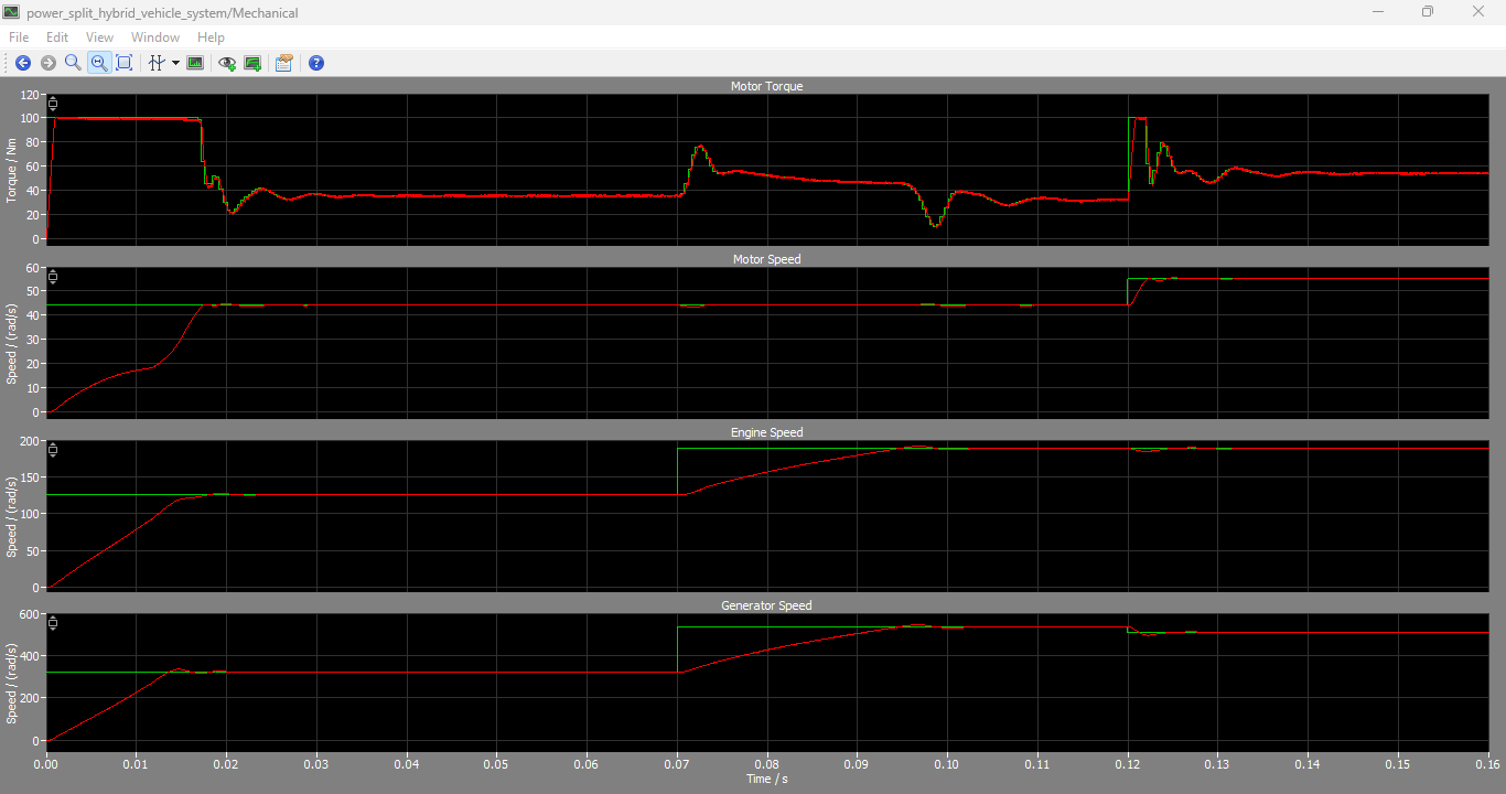
Figure 5: Motor Torque, Motor Speed, Engine Speed and Generator Speed output Graphs generated in PLECS Simulation
You can download the Project files here: Download files now. (You must be logged in).
Figure 5 presents the simulated mechanical performance waveforms of the hybrid vehicle system, including motor torque, motor speed, engine speed, and generator speed. The results demonstrate the coordinated operation of MG1, MG2, and the engine during startup and acceleration. The motor torque profile reflects the propulsion demand, while the speed responses indicate effective tracking of the desired operating points. These waveforms verify the successful interaction between the electrical and mechanical subsystems of the power-split hybrid vehicle.
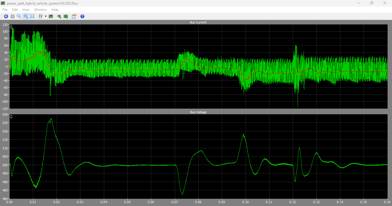
Figure 6: DC Bus Current and Voltage output graphs in PLECS
Figure 6 presents the DC bus current and voltage waveforms obtained from the PLECS simulation. The results show that the bidirectional DC/DC converter successfully maintains the DC bus voltage close to its reference value despite variations in load demand and operating conditions. The current waveform illustrates the dynamic power exchange between the battery and the electrical drive system, confirming stable energy management and effective voltage regulation throughout the simulation period.
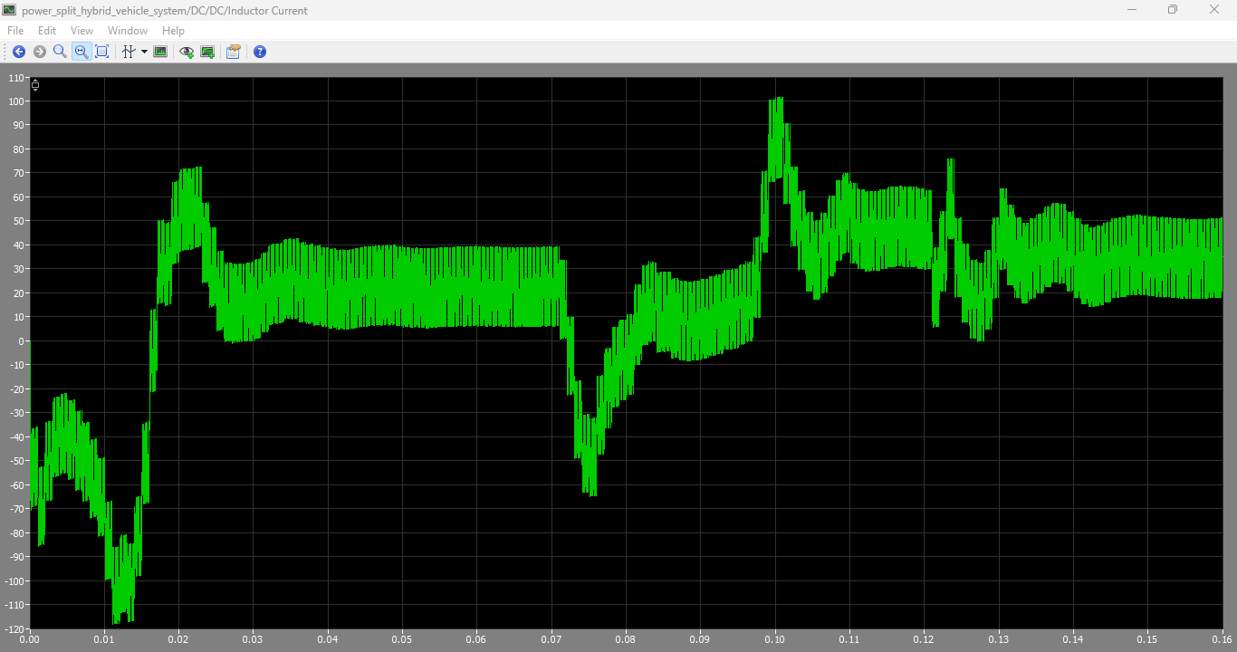
Figure 7: Inductor output current output graph of DC DC converter
You can download the Project files here: Download files now. (You must be logged in).
Figure 7 presents the output inductor current waveform of the DC/DC converter used in the hybrid vehicle system. The inductor current plays a crucial role in energy transfer between the battery and the DC bus while minimizing current ripple and improving converter efficiency. The waveform demonstrates the converter’s switching operation and current regulation capability, indicating proper energy flow control and stable converter performance under varying load conditions.
The operating sequence consists of three stages:
Stage 1: Initial Startup
- MG2 accelerates the wheel from standstill while MG1 accelerates the engine to approximately 125 rad/s (1200 rpm).
Stage 2: Engine Speed Increase
- At 70 ms, the engine speed reference is increased to approximately 188 rad/s (1800 rpm) while maintaining constant wheel speed.
Stage 3: Vehicle Acceleration
- At 120 ms, the wheel speed reference is increased while the engine remains at 1800 rpm.
This sequence demonstrates the interaction between propulsion, generation, and engine regulation functions.
X. Results and Discussion
Simulation results confirm successful operation of the proposed hybrid system.
A. Mechanical Performance
The wheel accelerates smoothly from standstill to the desired speed. MG2 produces the required propulsion torque during acceleration.
MG1 successfully regulates engine speed throughout the simulation. During startup, MG1 operates as a motor to accelerate the engine. Once the desired speed is achieved, MG1 transitions into generator mode.
The engine speed closely follows the reference commands, demonstrating effective speed regulation.
B. Torque Characteristics
Motor torque increases rapidly during acceleration phases and decreases once steady-state conditions are reached.
The coordinated torque contribution from the engine and MG2 ensures smooth vehicle operation and reduced transient disturbances.
C. DC Bus Voltage Regulation
The DC bus voltage remains close to the desired 500 V reference throughout the simulation.
Minor voltage deviations occur during transient events; however, the bidirectional converter quickly restores the voltage to the reference level.
This demonstrates the effectiveness of the converter control strategy and battery support system.
D. Engine Operating Point
The engine torque-speed trajectory remains within the efficient operating region obtained from BSFC optimization data [2].
Maintaining engine operation within this region improves fuel economy and reduces energy losses.
E. Battery Performance
The battery successfully supplies and absorbs energy as required by the system.
During acceleration, energy flows from the battery to the motors. During generator operation, energy is transferred back to the battery, demonstrating bidirectional power capability.
Overall, the simulation validates the functionality of the power-split hybrid architecture and confirms proper interaction among all subsystems.
XI. Advantages of the Proposed System
The developed power-split HEV offers several advantages:
- Improved fuel efficiency through optimal engine operation.
- Flexible power sharing between electrical and mechanical paths.
- Stable DC bus voltage regulation.
- Enhanced vehicle acceleration using electric motor assistance.
- Reduced battery stress through controlled energy management.
- Capability for regenerative energy recovery.
- Efficient engine speed regulation using MG1.
These features make power-split architectures attractive for modern hybrid vehicle applications.
XII. Conclusion
This paper presented the modeling and simulation of a lithium-ion battery-powered power-split hybrid electric vehicle using the PLECS simulation platform. The system integrates a bidirectional DC/DC converter, lithium-ion battery, dual PMSM drive systems, internal combustion engine, and planetary gear set to achieve efficient energy management and propulsion control.
The resistor-only battery model provided an effective representation of lithium-ion battery behavior, while the DC/DC converter maintained a stable 500 V DC bus. MG2 supplied traction power, whereas MG1 regulated engine speed and facilitated power generation. The planetary gear set successfully enabled power splitting between electrical and mechanical paths.
Simulation results demonstrated successful startup, wheel acceleration, engine speed tracking, and DC bus voltage regulation. Furthermore, the engine operated near its optimal BSFC region, contributing to improved efficiency.
The presented model provides a valuable platform for future investigations involving advanced energy management algorithms, regenerative braking strategies, battery aging studies, and optimization of hybrid vehicle performance.
References
[1] O. Tremblay and L.-A. Dessaint, “Experimental Validation of a Battery Dynamic Model for EV Applications,” World Electric Vehicle Journal, vol. 3, pp. 1–10, May 2009.
[2] J. Liu and H. Peng, “Modeling and Control of a Power-Split Hybrid Vehicle,” IEEE Transactions on Control Systems Technology, vol. 16, no. 6, pp. 1242–1251, Nov. 2008.
[3] C. C. Chan, “The State of the Art of Electric and Hybrid Vehicles,” Proceedings of the IEEE, vol. 90, no. 2, pp. 247–275, 2002.
[4] M. Ehsani, Y. Gao, and A. Emadi, Modern Electric, Hybrid Electric, and Fuel Cell Vehicles, 2nd ed. Boca Raton, FL, USA: CRC Press, 2018.
[5] I. Husain, Electric and Hybrid Vehicles: Design Fundamentals, 3rd ed. Boca Raton, FL, USA: CRC Press, 2021.
[6] J. Larminie and J. Lowry, Electric Vehicle Technology Explained, 2nd ed. Chichester, U.K.: Wiley, 2012.
[7] S. Onori, L. Serrao, and G. Rizzoni, Hybrid Electric Vehicles: Energy Management Strategies. London, U.K.: Springer, 2016.
[8] A. Emadi, K. Rajashekara, S. Williamson, and S. Lukic, “Topological Overview of Hybrid Electric and Fuel Cell Vehicular Power System Architectures and Configurations,” IEEE Transactions on Vehicular Technology, vol. 54, no. 3, pp. 763–770, 2005.
[9] B. K. Bose, Modern Power Electronics and AC Drives. Upper Saddle River, NJ, USA: Prentice Hall, 2002.
[10] J. M. Miller, Propulsion Systems for Hybrid Vehicles, 2nd ed. London, U.K.: IET Press, 2010.
You can download the Project files here: Download files now. (You must be logged in).






Responses