

Gear Ratio and Involute Gear Calculator
Calculate gear-train ratio, speed and torque; inspect a rotating involute spur pair with profile shift and contact ratio, then compare road speed by gear.

This gear ratio calculator connects tooth counts to shaft speed, torque and power, and shows how the geometry of an involute spur gear pair affects its mesh. It is intended for engineers comparing mechanisms, students checking machine-design exercises, and builders estimating a drivetrain before choosing components.
Start with the driver and driven tooth counts. The reported reduction ratio is input speed divided by output speed: a value of two means the output turns at half the input speed. Enter shaft speed, torque and an estimated mesh efficiency to calculate delivered torque and power. Enable the second external stage when the driven shaft carries another pinion. Ratios multiply, efficiencies multiply, and two external meshes restore the original rotation direction. The drawing and detailed geometry always describe the first stage.
For the involute gear calculator, specify module or diametral pitch and a common reference pressure angle. Profile shift changes reference tooth thickness and the center distance required for a theoretical zero-backlash mesh. The calculator solves the working pressure angle rather than assuming that it remains equal to the reference angle. Choose either clearance-preserving tip shortening, following the KHK example, or unshortened shifted addenda. Existing gears must be evaluated using their actual tip dimensions and manufacturing convention.
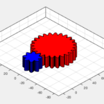
Press play beside the mesh-cycle input to watch opposite rotation through one tooth pitch. The illustration uses calculated involute flanks, working pitch circles and the active contact segment. Root connectors are simplified; this is not a manufacturing drawing or a cutter-generated tooth profile. The dimension table reports the two gears' reference, working, base, tip and root diameters and top-land thickness.
Contact ratio is the active path length divided by base pitch. It describes engagement overlap rather than reduction. A value above one is necessary for continuous ideal spur engagement. Read the undercut and thin-tip messages before interpreting this result: cutter geometry, tolerances and root transitions can reduce the usable involute.
The separate vehicle section calculates speed in six editable forward gears and engine RPM at a chosen cruising speed. Enter the final-drive ratio and effective rolling tire diameter. The default transmission ratios are illustrative, not a vehicle specification. The chart shows kinematic road speed versus engine RPM; it does not predict attainable top speed, acceleration or traction.
Use the metric/US switch to display lengths, torque, forces and road speeds in your preferred units. This tool covers external, parallel-axis spur gears in steady operation. It does not rate bending strength, pitting life, lubrication, temperature, noise or backlash allowances, and it does not model helical, bevel, internal or planetary gearing.
How it is calculated
For each external mesh, the reduction convention is . A compound train multiplies stage ratios and efficiencies; and . Speeds and torques are magnitudes; each external mesh reverses rotation. This follows KHK Gear Technical Reference, attached page 5, Table 2.1 (printed page 600).
The involute is , with the subtracted angle in radians. Solve by bracketed bisection. Then and . Reference and base radii are and . KHK attached pages 6–9 provide the involute, undercut and shifted-pair equations.
With , the KHK option uses ; the unshortened option uses . Both use . KHK Table 4.3 preserves radial clearance by shortening both tips. KHK Table 3.5 describes the unshortened individual-gear convention; KG Table 15's published contact ratio is consistent with that convention.
The contact path is and . Radii, rather than diameters, belong inside these square roots (KG attached page 2). Top-land arc thickness follows the involute tooth half-angle. The full-depth rack undercut screen is . Mesh force is the ideal input torque divided by working pitch radius; separating force is .
Vehicle speed follows wheel rotations times rolling circumference: wheel RPM = engine RPM divided by transmission and final-drive ratios. The cruise calculation reverses this relation. Explicit unit conversions handle RPM, angular speed, power and road speed. The vehicle model follows the TREMEC Toolbox instructions.
Assumptions
- External involute spur gears share module and reference pressure angle; parallel, rigid shafts and a standard full-depth rack with addendum coefficient 1 and dedendum coefficient 1.25.
- Working center distance is the theoretical zero-backlash distance implied by the chosen shifts. Existing gears with independently fixed center distance or tooth thinning need a different backlash calculation.
- Profile shifts and efficiency values are user inputs, not material or catalogue recommendations. The optional second stage contributes ratio and losses only; its tooth geometry is not checked.
- The drawing samples involute flanks with ten points per side and joins them to root-circle arcs using radial connectors. It omits trochoidal fillets, cutter-tip radius, undercut removal and face width.
- The play input advances one tooth pitch per cycle at an illustrative rate independent of entered RPM. Only the drawing transforms depend on it; outlines and engineering calculations remain cached.
- Steady torque, constant estimated efficiency and no slip. Tire diameter is an effective rolling diameter; six default car ratios are illustrative.
Where it applies
Use for preliminary geometry and kinematics, not gear strength certification or manufacturing export. Ratios remain valid when warnings flag undercut, but the reported ideal involute contact ratio may then overestimate actual usable engagement. Increase tooth count or shift and check a cutter-generated profile before selecting such gears.
Errors suppress results for a non-real working angle, pointed teeth, an invalid tip/root arrangement, below-base-circle or root interference, inadequate root clearance, or contact ratio at or below one. A top land below 0.25 module and a contact ratio below 1.2 are advisory screening thresholds chosen here, not compliance criteria. Positive top-land thickness alone does not guarantee manufacturability.
The model excludes elastic deflection, dynamic loads, material strength, heat treatment, lubrication, wear, actual backlash, bearing loads beyond ideal mesh forces and thermal growth. It implements manufacturer geometry equations and makes no claim of ISO, DIN, AGMA or JIS design compliance. Check against the standard in force when specifying a production gear.
Vehicle results assume locked mechanical drive, no tire slip or torque-converter slip and constant rolling diameter. Drag, engine power, rev limits, road loads and tire growth determine attainable speed separately.
References
- KHK, Gear Technical Reference, §§2.2–4.1, Tables 2.1, 3.5, 4.3 and 10.1; attached pages 5–9 and 37. https://khkgears.net/wp-content/uploads/2015/10/gear_guide.pdf
- KHK, Calculation of Gear Dimensions, Table 4.3: clearance-preserving shifted spur pair. https://khkgears.net/new/gear_knowledge/gear_technical_reference/calculation_gear_dimensions.html
- KG Stock Gears, Technical Data §1.9, Contact ratio and Specific sliding, printed pp. 34–36; attached pages 1–3. https://www.kggear.co.jp/en/wp-content/themes/bizvektor-global-edition/pdf/1.9_Contact-ratio-and-Specific-sliding_TechnicalData_KGSTOCKGEARS.pdf
- TREMEC, Toolbox RPM Calculator Instructions, p. 1, including the Magnum 2.66 example screenshot. https://tremec.com/wp-content/uploads/2023/03/RPM-Calculator_Instructions.pdf
Inputs
| Input | Symbol | Unit | Default |
|---|---|---|---|
| Tooth size specified by | pitch_basis | Module | |
| Module Reference diameter divided by tooth count. | m_set | mm | 3 |
| Diametral pitch Teeth per inch of reference diameter. | P_d | 1/in | 8 |
| Driver teeth | z_1 | 20 | |
| Driven teeth | z_2 | 40 | |
| Reference pressure angle Both gears share this angle and tooth size. | alpha | deg | 20 |
| Driver profile shift Dimensionless rack shift. Positive values thicken the reference tooth. | x_1 | 0 | |
| Driven profile shift Working center distance is solved for zero theoretical backlash. | x_2 | 0 | |
| Shifted-gear tip convention Both options use full-depth rack roots. The KHK option shortens both tips to retain 0.25 module root clearance. | tip_rule | KHK: preserve 0.25 module clearance | |
| Driver speed Speed magnitude; external meshes reverse direction. | n_in | rpm | 1500 |
| Driver torque Steady input torque, before losses. | T_in | N*m | 10 |
| First-stage efficiency User estimate: 0.97 means 97%. Affects torque and power, not ratio. | eta_1 | 0.97 | |
| Add a second external gear stage Gear 3 shares the shaft of gear 2. The drawing and geometry apply to stage 1. | stage_two | false | |
| Second-stage driver teeth | z_3 | 20 | |
| Second-stage driven teeth | z_4 | 60 | |
| Second-stage efficiency Applied only when the second stage is enabled. | eta_2 | 0.97 | |
| Mesh cycle · press ▶ to rotate One cycle advances the driver by one tooth pitch. Illustration speed is independent of shaft RPM. | mesh_phase | 0.25 | |
| Engine speed Independent of the industrial gear-pair speed. | n_engine | rpm | 3000 |
| Effective rolling tire diameter Use measured rolling circumference divided by pi when available; nominal sidewall diameter is only an estimate. | D_roll | mm | 650 |
| Final-drive ratio Input speed divided by wheel speed at the axle. | r_axle | 3.73 | |
| 1st gear ratio Illustrative ratios; enter the actual gearbox data. | g_1 | 3.5 | |
| 2nd gear ratio Input speed divided by output speed. | g_2 | 2.1 | |
| 3rd gear ratio Input speed divided by output speed. | g_3 | 1.4 | |
| 4th gear ratio A ratio of 1 is direct drive. | g_4 | 1 | |
| 5th gear ratio Ratios below 1 are overdrive. | g_5 | 0.8 | |
| 6th gear ratio All six ratios can be edited independently. | g_6 | 0.65 | |
| Gear for cruise RPM | selected_gear | 6 | |
| Cruising road speed Used only for the cruise RPM result. | v_target | km/h | 100 |
Results
With the default inputs above, the calc gives:
| Result | Value |
|---|---|
| Overall input/output speed ratio | 2 |
| Final shaft speed | 750 1/min |
| Final shaft torque | 19.4 N·m |
| Delivered shaft power | 1.524 kW |
| Final rotation relative to input | Opposite to input |
| Stage 1 working center distance | 90 mm |
| Stage 1 working pressure angle | 20 deg |
| Stage 1 contact ratio | 1.635 |
| Stage 1 ideal tangential force | 333.3 N |
| Stage 1 ideal separating force | 121.3 N |
| Engine speed at chosen cruise speed | 1,979 1/min |
Checked against sources
Each case below was calculated by this calc and agrees with the value from its source (within the tolerance where one is shown).
KHK Table 4.3 · shifted 12/24 pair
Source: KHK Gear Technical Reference Table 4.3, printed p. 608 (attached p. 9). Module 3, 20°, z=12/24, shifts 0.6/0.36. Published dimensions are rounded; KHK tip shortening retains 0.25m clearance.
Inputs: Driver teeth = 12; Driven teeth = 24; Driver profile shift = 0.6; Driven profile shift = 0.36; the others as above.
| Result | Source | This calc |
|---|---|---|
| Stage 1 working pressure angle | 26.089 deg | 26.089 deg |
| Stage 1 working center distance | 56.5 mm | 56.5 mm |
| Driver tip diameter | 44.84 mm | 44.84 mm |
| Driven tip diameter | 79.4 mm | 79.4 mm |
| Driver root diameter | 32.1 mm | 32.1 mm |
| Driven root diameter | 66.66 mm | 66.66 mm |
KHK Table 10.1 · 20/40 contact ratio
Source: KHK Gear Technical Reference Table 10.1, printed p. 664, attached p. 37. Read row 40 and column 20 at 20°: 1.635. Table rounds to three decimals.
Inputs: the default inputs above.
| Result | Source | This calc |
|---|---|---|
| Stage 1 contact ratio | 1.635 | 1.635 |
KHK Table 2.1 · two-stage train
Source: KHK Gear Technical Reference Table 2.1, printed p. 600, attached p. 5: 10/24 and 12/30 teeth, 1200 rpm input, 500 rpm intermediate, 200 rpm final. Added shifts are geometry-only trial inputs and do not enter these kinematic reference values.
Inputs: Driver teeth = 10; Driven teeth = 24; Second-stage driver teeth = 12; Second-stage driven teeth = 30; Add a second external gear stage = yes; Driver speed = 1,200 rpm; Driver profile shift = 0.6; Driven profile shift = 0.36; the others as above.
| Result | Source | This calc |
|---|---|---|
| Stage 1 reduction ratio | 2.4 | 2.4 |
| Stage 2 reduction ratio | 2.5 | 2.5 |
| Overall input/output speed ratio | 6 | 6 |
| Stage 1 output speed | 500 rpm | 500 rpm |
| Final shaft speed | 200 1/min | 200 1/min |
KG Table 15 · unshortened shifted contact ratio
Source: KG Stock Gears Technical Data §1.9, Table 15, printed p. 36, attached p. 3. z=12/40, x=0.5/0, module 2, pressure angle 20°. Published 1.399 is consistent with unshortened addenda; KHK clearance-preserving tip shortening gives a different result and is not used for this case.
Inputs: Module = 2 mm; Driver teeth = 12; Driver profile shift = 0.5; Shifted-gear tip convention = Unshortened: addendum = module × (1 + shift); the others as above.
| Result | Source | This calc |
|---|---|---|
| Stage 1 contact ratio | 1.399 | 1.399 |
TREMEC screenshot · 70 mph cruise
Source: TREMEC Toolbox RPM Calculator Instructions, p. 1, left screenshot (visually read): 70 mph, 4.1 axle, 25.68 in tire, 0.63 sixth ratio, result 2367 rpm. Inputs converted exactly: 25.68 in = 652.272 mm; 70 mph = 112.65408 km/h. Tolerance allows the displayed integer rounding. Image digits are not in the PDF text layer.
Inputs: Effective rolling tire diameter = 652.3 mm; Final-drive ratio = 4.1; 6th gear ratio = 0.63; Cruising road speed = 112.7 km/h; the others as above.
| Result | Source | This calc |
|---|---|---|
| Engine speed at chosen cruise speed | 2,367 1/min | 2,367 1/min |
KHK Table 3.3 · diametral pitch conversion
Source: KHK Gear Technical Reference Table 3.3, printed p. 602, attached p. 6: module 3.17500 corresponds to DP 8.00000.
Inputs: Tooth size specified by = Diametral pitch (teeth/in); the others as above.
| Result | Source | This calc |
|---|---|---|
| Module used | 3.175 mm | 3.175 mm |













Responses