

BESS Container Spacing and Radiant Heat
Calculate fire radiation, transient wall and cell heating, and separation distance for neighbouring BESS containers. Compare open exposure with a heated barrier wall.

BESS container separation distance depends on the fire history, the radiation geometry and how quickly heat passes through the neighbouring enclosure. This calculator connects those effects. It is intended for engineers comparing layouts, students studying fire heat transfer and technical users examining why a barrier wall may reduce exposure.
Enter the container dimensions and clear face-to-face gap. The fire scenario uses a published full-scale LFP rack test from FM Global. Choose how many rack equivalents burn, whether their histories start together, and the power and duration multipliers. The default is an extrapolated multi-rack container scenario: it is not a measured fire test of a particular commercial container. For project analysis, the builder should replace the source curve with the representative container's test history.
Set the neighbouring wall's steel skins, insulation properties and the thermal capacity of the nearest cells. The wall-to-cell conductance represents the gap and mounting contacts. Use the propagation temperature established for the cells and state of charge under investigation. The default threshold illustrates the calculation; chemistry names alone do not establish a reliable propagation temperature.
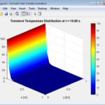
The model calculates a Heskestad flame height and a solid-flame emissive power. Numerical integration of rectangular view factors gives the incident radiant heat flux versus distance. A transient one-dimensional conduction solution then follows the outer skin, insulation, inner skin and cell node through the fire and the observation period. The cell temperature may peak after the heat-release rate has fallen. Press play to see heat penetration across the selected wall at successive times.
The barrier comparison includes its position, height, thickness and thermal properties. The wall must span the complete facing lengths and remain intact. It blocks direct rays but absorbs heat and emits radiation from its rear face; an ideal cold shield would overstate its benefit. The separation chart compares both configurations against the entered cell threshold. A spacing equal to the 0.5 m search floor indicates that the crossing lies below the searched range. It does not recommend installing containers at that distance.
NFPA 855 spacing is a separate design constraint. The calculator displays the familiar 3 ft group-spacing benchmark, while the 2026 edition's large-scale fire-test context and UL 9540A sixth edition require attention to representative installation conditions. A calculated radiant exposure cannot replace accepted test evidence or authorize a reduced separation.
This tool does not evaluate vent jets, direct flame contact, wind, hot-gas transport, gas explosions, debris, enclosure openings, structural fire resistance or propagation inside the source container. Constant effective material properties also omit concrete spalling and insulation degradation. Installation work belongs to a qualified person. Use the adopted standard, manufacturer instructions and project-specific fire engineering assessment, and check against the standard in force.
How it is calculated
The imposed heat-release history is a pixel digitization of the chemical HRR in FM Global's full-scale LFP rack test (2019, Fig. 6-15, attached PDF p. 68). Delayed copies are summed for the chosen rack count and scaled in power and local duration. Each rack is evaluated at : the duration multiplier never changes the entered physical ignition interval . This produces a container fire scenario, not a measured container-wide burn. Original test time, including the ignition delay, is retained.
Heskestad gives the mean flame extension with in kW and in m. The effective four-sided solid-flame envelope extends from grade to . Its uniform emissive power is ; all prescribed radiative power is assigned to the four vertical faces. Only the facing face is visible to the aligned neighbour.
For a differential receiver, . The width integral is evaluated analytically and the height integral by midpoint strips, automatically refined when height/separation is large. For a full-length barrier at fraction of the gap, rays below source height are blocked. The largest received flux over sampled receiver heights drives the wall column. Its location may change with time.
The barrier is a 1D concrete slab with finite-difference nodes at both faces. The neighbour comprises two lumped steel skins, finite-volume insulation cells and a nearest-cell thermal-capacitance node coupled through the entered conductance. Backward Euler advances . Interface conductances use half-cell thermal resistances. Newton iterations solve the nonlinear boundary losses; ambient convection is included. The barrier's hot rear face radiates through its own rectangular view factor onto the neighbour. Both scenarios continue through the post-fire observation period.
Radiation is evaluated on a separate event timeline containing every delayed fire-history breakpoint, every crossing of a radiation-power lookup node, and additional samples no farther apart than the radiation-event step. Reported flux maxima use this timeline, independently of the thermal grid. Exact integrals of the piecewise-linear incident flux provide interval-mean thermal forcing, preserving short-pulse energy. Barrier rear temperatures are interpolated from the conduction solution onto the radiation timeline before reradiation is added.
The first cell-threshold crossing is interpolated in time. The spacing search includes the selected gap and logarithmically spaced seed distances. It then solves additional barrier-maximum candidates and brackets the last threshold crossing in each scenario. PCHIP proposes new distances; the reported spacing is the first actually solved below-threshold endpoint of the final bracket, whose width is bounded by the spacing tolerance. A 0.5 m result means every resolved search temperature is below threshold, including the selected gap. A blank spacing means the search range or six refinement rounds are insufficient; a blank threshold time means no crossing during observation.
Assumptions
Parallel, equal-length, aligned containers; upright, buoyancy-dominated fire without wind or flame impingement. The opaque, intact barrier spans at least the entire facing length of both containers, has no penetrations, starts at grade and occupies the entered position. Its thickness enters heat diffusion and front/rear surface distances; its centre plane defines the geometric shadow.
Time-varying peak exposure is applied to one thermal column. For the barrier, this also applies the hottest local rear-face temperature uniformly over its emitting rectangle. The sum of separate maxima for direct and rear-face radiation is conservative with respect to the chosen geometry. Lateral spreading, reflection between surfaces and mutual thermal feedback are omitted. Atmospheric transmission is unity; smoke attenuation is not credited.
Material properties are constant effective values. Illustrative stainless-steel, mineral-wool and concrete properties follow Martelletto et al. (2021), Table 2; insulation conductivity should be replaced by its hot-condition value. The cell heat capacity, coupling and 150 °C default threshold are scenario inputs, not a universal LFP ignition model. Cell self-heating and chemical reactions begin outside this passive thermal model; temperatures shown after a threshold crossing are hypothetical.
Where it applies
This is a radiation and passive-heating exposure calculation, not evidence that a BESS installation will avoid fire propagation. Door or vent jets, wind-tilted flames, hot gases, burning debris, enclosure failure, cable paths, internal propagation, gas accumulation and deflagration require separate assessment. A wall can block radiation while failing to control these other routes. Check the actual tested enclosure, state of charge, cell chemistry, vent arrangement and barrier configuration.
NFPA 855 2026 edition and UL 9540A 6th edition (March 13, 2026) are the comparison basis, reviewed November 2, 2026. The displayed 3 ft group-spacing benchmark is not a universal clearance for a container holding hundreds of kWh or MWh. The open NFPA committee record is development material, not the final normative text. Follow the adopted final edition, installation instructions, HMA and accepted installation-level large-scale fire-test evidence; check against the standard in force. The calculated distance never authorizes reduced spacing. UL's public guidance describes the edition-6 post-deflagration test with intentionally ignited vent gases.
The public HRR source is rack-scale. Rack-to-container scaling, ignition synchronization and power/duration multipliers are explicit extrapolations; they do not capture ventilation limitation, oxygen availability or container-specific test behaviour. The digitized history integrates to about 3.98 GJ per rack, approximately 4% above the report's independently stated 3.81 GJ. Neither the history nor the equations are normalized to match that total. Raster resolution and overlapping traces limit fidelity; some instantaneous peaks are unresolved. The separately reported 2540 kW rack peak bounds the radiation lookup. Replace the source curve with representative open or licensed test data through the builder for project work.
Defaults use 12 through-thickness cells, a maximum 120 s thermal step, 61 radiation-power samples, 17 receiver heights, 13 initial logarithmic separation samples, a 0.01 m crossing tolerance and a maximum 60 s radiation-event interval. The event and adaptive solves raised runtime above approximately 3 s with denser initial grids; these defaults retain the complete heat-transfer model. Interval means preserve incident pulse energy, but backward Euler can smooth the temperature response and shift threshold times by roughly a thermal step. Refine the advanced controls for marginal cases. Adaptive maxima are checked to approximately 0.01 K; search results remain numerical estimates over the entered range. Separation and wall-profile pictures use PCHIP interpolation between solved samples; radiation histories use linear lookup interpolation. Automated checks cover doubled layer meshes, halved thermal steps, both peak-flux outputs, refined radiation integration, open-gap and barrier-spacing convergence, ignition-delay invariance, and energy balances. Extend observation when temperatures are still rising. Concrete moisture, spalling, degradation and temperature-dependent properties are outside the model.
References
- FM Global, Ditch and Zeng, Development of Sprinkler Protection Guidance for Lithium Ion Based Energy Storage Systems (2019), pp. 49–50; https://www.fm.com/-/media/Files/FM-Global/Research-Technical-Reports/Development_of_Sprinkler_Protection_Guidance_for_Lithium_Ion_BasedEnergy_Storage_Systems.pdf
- Heskestad, Fire Plumes, Flame Height, and Air Entrainment, SFPE Handbook of Fire Protection Engineering, 5th ed. (2016), DOI: 10.1007/978-1-4939-2565-0_13. Solid-flame radiation framework: SFPE Handbook, 5th ed., DOI: 10.1007/978-1-4939-2565-0.
- Smith and Hoehler, Imaging Through Fire Using Narrow-Spectrum Illumination, NIST manuscript, flame-height example on PDF p. 11; https://tsapps.nist.gov/publication/get_pdf.cfm?pub_id=925024
- Howell, A Catalog of Radiation Heat Transfer Configuration Factors, B-3, parallel rectangle; https://www.thermalradiation.net/sectionb/B-3.html
- Martelletto, Doretti and Mancin, Numerical simulation of latent and sensible concrete thermal energy storage system (2021), Table 2, DOI: 10.18462/iir.PCM.2021.2081; https://www.research.unipd.it/retrieve/267daaaf-0eb4-4de8-9649-d53b1e9f44d7/IIR_PCM2021_ID2081.pdf
- NFPA 855, Standard for the Installation of Stationary Energy Storage Systems, 2026 edition; https://www.nfpa.org/codes-and-standards/nfpa-855-standard-development/855
- NFPA 855 2026-cycle public committee record (development material); https://docinfofiles.nfpa.org/files/AboutTheCodes/855/855_A2025_ESS_AAA_SD_MeetingAgenda_0824.pdf
- UL 9540A, 6th ed. (2026); UL Solutions, Understanding UL 9540A, NFPA 855 and Large-Scale Fire Testing for Battery Energy Storage Systems; https://www.ul.com/thecodeauthority/knowledge/understanding-UL-9540A-NFPA-855
- Carslaw and Jaeger, Conduction of Heat in Solids, 2nd ed., Oxford (1959), constant-flux semi-infinite solid; https://global.oup.com/academic/product/conduction-of-heat-in-solids-9780198533689
Inputs
| Input | Symbol | Unit | Default |
|---|---|---|---|
| Container face separation | gap | m | 2.5 |
| Facing container length | fire_w | m | 6.06 |
| Container depth | fire_b | m | 2.44 |
| Container height | box_h | m | 2.59 |
| Burning rack equivalents | rack_n | 8 | |
| Delay between rack ignitions Zero starts all rack histories together. | rack_lag | s | 0 |
| Heat-release multiplier Scales the digitized FM Global LFP rack curve. | hrr_scale | 1 | |
| Fire duration multiplier | time_scale | 1 | |
| Radiative fraction | chi_rad | 0.35 | |
| Initial temperature | ambient_t | °C | 25 |
| Each steel skin thickness | skin_t | mm | 1.5 |
| Insulation thickness | ins_t | mm | 10 |
| Effective insulation conductivity Use the hot-condition value for the actual panel. | ins_k | W/(m*K) | 0.05 |
| Insulation volumetric heat capacity | ins_cv | J/(m^3*K) | 154500 |
| Nearest-cell areal heat capacity Use only the cell mass thermally coupled to this wall area. | cell_cap | J/(m^2*K) | 20000 |
| Inner wall to cell conductance Represents the air gap, radiation and mounting contacts. | cell_link | W/(m^2*K) | 8 |
| Cell propagation threshold Replace with the cell-specific threshold from testing. | prop_t | °C | 150 |
| Neighbour absorptivity and emissivity | surface_eps | 0.9 | |
| Ambient convection coefficient | h_conv | W/(m^2*K) | 10 |
| Barrier height | bar_h | m | 4 |
| Barrier thickness | bar_t | mm | 150 |
| Barrier conductivity | bar_k | W/(m*K) | 1.77 |
| Barrier volumetric heat capacity | bar_cv | J/(m^3*K) | 1455586 |
| Barrier absorptivity and emissivity | bar_eps | 0.9 | |
| Barrier position in gap Fraction measured from the burning container to the wall centre. | bar_pos | 0.5 | |
| Post-fire observation | cool_time | s | 7200 |
| Maximum time step | time_step | s | 120 |
| Cells through insulation and barrier | mesh_n | 12 | |
| Minimum radiation strips | quad_n | 24 | |
| Receiving wall height samples | height_n | 17 | |
| Heat-release interpolation points | q_samples | 61 | |
| Initial separation samples | sweep_n | 13 | |
| Largest separation searched | search_max | m | 15 |
| Exposure time | t_show | s | 5100 |
| Wall profile shown | view_case | Open gap | |
| Peak-radiation sampling interval Fire breakpoints and delayed events are always included. | event_step | s | 60 |
| Separation search tolerance | search_tol | m | 0.01 |
Results
With the default inputs above, the calc gives:
| Result | Value |
|---|---|
| Open-gap threshold spacing | 3.18 m |
| Barrier threshold spacing, bounded search | 0.5 m |
| Peak cells, open gap | 166 °C |
| Peak cells, with barrier | 45.2 °C |
| Time to cell threshold, open gap | 6,252 s |
| Peak incident radiation, open gap | 25.85 kW/m² |
| Peak incident radiation, with barrier | 2.51 kW/m² |
| NFPA group-spacing benchmark | 0.914 m |
| Open-gap exposure criterion | Open gap reaches cell threshold |
| Barrier exposure criterion | Barrier below search floor |
It also shows: Time to cell threshold, barrier; blank if not reached, s.
Checked against sources
Each case below was calculated by this calc and agrees with the value from its source (within the tolerance where one is shown).
NIST 800 kW square burner
Source: Smith and Hoehler, Imaging Through Fire Using Narrow-Spectrum Illumination, NIST author manuscript, PDF p. 11. Published rounded Heskestad result for an 800 kW, 1 m square burner.
Inputs: the default inputs above.
| Result | Source | This calc |
|---|---|---|
| NIST flame-height benchmark | 2.25 ± 0.01 m | 2.256 m |
Howell differential element to parallel square
Source: Howell, A Catalog of Radiation Heat Transfer Configuration Factors, B-3 (Hottel 1931; Hamilton and Morgan 1952), https://www.thermalradiation.net/sectionb/B-3.html. Four corner-rectangle analytical factors with a=b=c=1 give 4 atan(1/sqrt(2))/(pi sqrt(2)) = 0.55412642398. Independent closed-form benchmark for the strip quadrature.
Inputs: the default inputs above.
| Result | Source | This calc |
|---|---|---|
| Parallel square view-factor benchmark | 0.5541 | 0.5543 |
FM Global full-rack measured peak
Source: FM Global (2019), PDF p. 67, measured LFP full-rack peak. This verifies source-data transfer, not the container scaling or propagation model.
Inputs: Burning rack equivalents = 1; the others as above.
| Result | Source | This calc |
|---|---|---|
| Synchronous upper-bound heat release | 2,540 kW | 2,540 kW |
Semi-infinite constant-flux slab
Source: Carslaw and Jaeger, Conduction of Heat in Solids, 2nd ed., Oxford (1959), semi-infinite solid with constant surface flux. Closed form T_surface = 300 + 2 q sqrt(alpha t/pi)/k; q=1000 W/m², k=1 W/(m K), volumetric heat capacity=10^6 J/(m³ K), t=1000 s gives 335.682482 K. The separate 1 m slab benchmark uses 80 cells and 10 s steps; the insulated rear is over 30 penetration depths away. The numerical surface rise is about 1.2% below the semi-infinite analytical rise at this benchmark resolution; tolerance is 0.5 K.
Inputs: the default inputs above.
| Result | Source | This calc |
|---|---|---|
| Constant-flux slab surface benchmark | 335.7 ± 0.5 | 335.3 |
Related Resources
Related courses

IEC Electrical Schematics and Industrial Control Panels

Basic Electrical Controls & Diagram Reading




Responses