

ANSI-C Code Generation and Real-Time Simulation Validation of a Three-Phase 6-Pulse Thyristor Converter Using PLECS Coder

Author: Waqas Javaid
Abstract
The increasing adoption of real-time simulation platforms in power electronics and power system applications has created a growing demand for efficient plant models that accurately represent physical systems while maintaining computational efficiency. This paper presents the modeling, discretization, code generation, and validation of a three-phase 6-pulse thyristor converter using the PLECS Coder environment. The study focuses on generating ANSI-C code from an electrical subsystem and comparing the generated code performance against the original native PLECS implementation. A controlled rectifier employing six silicon-controlled rectifiers (SCRs) is modeled and regulated through a current control loop integrated with a phase-locked loop (PLL) synchronization mechanism. Different discretization step sizes are investigated to evaluate their influence on simulation accuracy. Results demonstrate that a discretization step size of 1×10⁻⁴ s provides excellent agreement between the generated-code implementation and the original continuous simulation model, whereas larger step sizes introduce significant deviations in current and voltage responses. The study confirms the effectiveness of PLECS Coder for generating real-time executable plant models suitable for hardware-in-the-loop (HIL) applications, rapid control prototyping, and digital twin development. The findings emphasize the importance of selecting appropriate discretization parameters to achieve a balance between computational efficiency and simulation fidelity.
I. Introduction
Power electronic converters are fundamental components in modern industrial systems, renewable energy installations, electric transportation platforms, and high-power motor drives. Among various converter topologies, the three-phase 6-pulse thyristor converter remains widely used due to its robustness, controllability, and suitability for medium- and high-power applications [1].
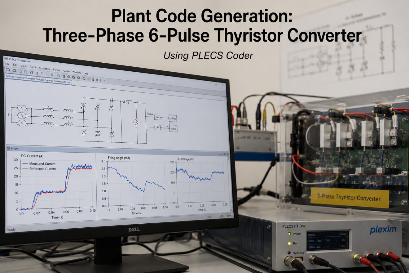
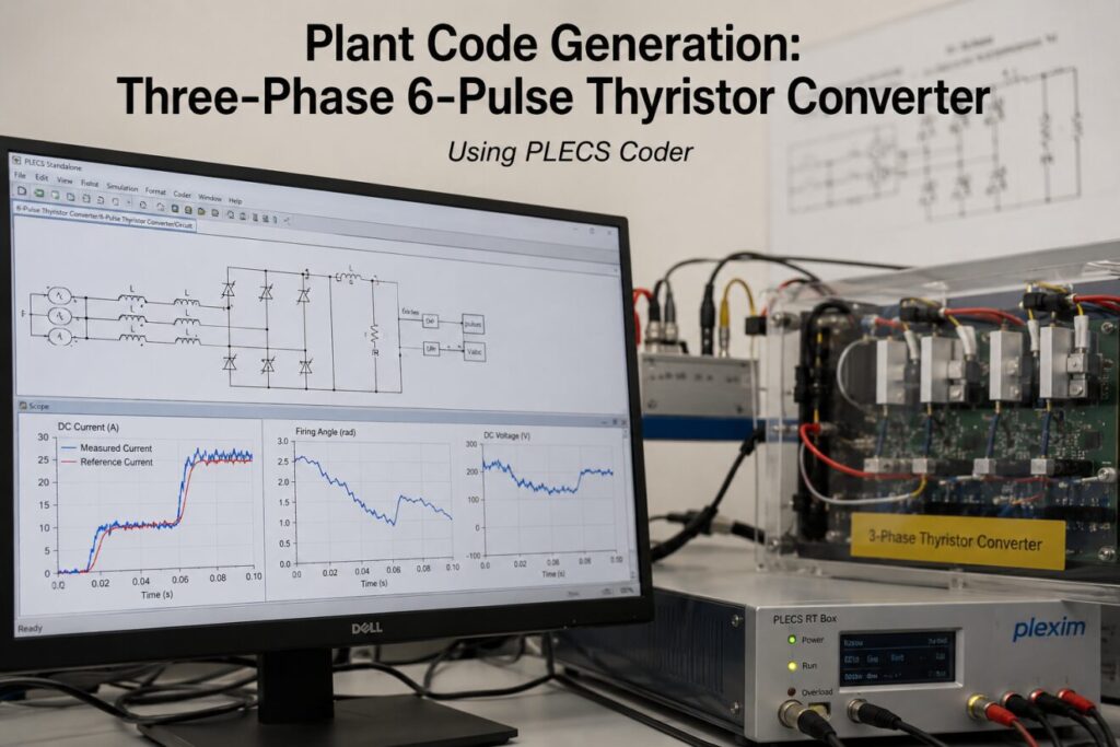
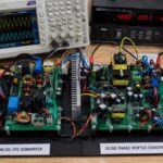
Figure 1: PLECS-based real-time simulation and ANSI-C code generation framework for a three-phase 6-pulse thyristor converter.
Figure 1 presents a realistic representation of the development and validation environment used for the three-phase 6-pulse thyristor converter investigated in this study. The image depicts a PLECS-based modeling workstation displaying the SCR rectifier circuit schematic along with key simulation outputs, including DC current tracking, firing angle variation, and DC voltage characteristics. The setup also includes a real-time simulation platform representing the deployment of automatically generated ANSI-C code for hardware-in-the-loop (HIL) and real-time testing applications. This development framework demonstrates the integration of power electronic converter modeling, control system implementation, code generation, and real-time execution, which are essential steps in validating high-fidelity plant models for industrial power electronics applications.
Traditionally, converter systems are analyzed using detailed simulation tools that solve circuit equations continuously or with adaptive numerical integration methods. Although such approaches provide high accuracy, they often require significant computational resources and may not be suitable for real-time execution environments. Real-time simulators, such as Hardware-in-the-Loop (HIL) platforms, require computationally efficient plant models capable of executing within fixed time intervals while maintaining acceptable accuracy [2].
To address these challenges, automatic code generation techniques have gained substantial importance. Modern simulation environments such as PLECS provide code generation capabilities that transform electrical and physical system models into optimized ANSI-C code. Generated code can then be deployed on embedded processors, real-time simulators, or custom computational platforms [3].
This paper investigates the code generation workflow for a three-phase 6-pulse thyristor converter using PLECS Coder. The electrical subsystem is discretized and converted into ANSI-C code, after which its behavior is compared against the original native PLECS simulation. Particular attention is given to the influence of discretization step size on simulation accuracy.
The objectives of this study are:
- To model a three-phase 6-pulse SCR converter in PLECS.
- To generate ANSI-C code for the electrical subsystem.
- To evaluate simulation accuracy under different discretization step sizes.
- To compare generated-code results with baseline native simulations.
- To assess the suitability of generated models for real-time applications.
II. System Description
The investigated system consists of a three-phase 6-pulse controlled rectifier supplied from a balanced three-phase AC source. The converter employs six thyristors arranged in a bridge configuration to convert AC power into a controllable DC output voltage [4].
The converter includes:
- Three-phase AC source
- Source inductances
- Six SCR devices
- DC-side smoothing inductor
- Resistive load
- Current control system
- Phase-Locked Loop (PLL)
- Pulse generation circuit
The input line voltage is set to 120 V while source inductances of 0.001 H are included to represent practical line impedance. On the DC side, a smoothing inductance of 0.02 H and a resistive load of 1 Ω are used to reduce current ripple and stabilize system operation.
The converter firing pulses are generated through a synchronized control mechanism. A PLL extracts phase information from the three-phase voltage source, allowing precise control of thyristor firing angles. The firing angle α is adjusted dynamically by the current controller to regulate the DC current according to a predefined reference signal.
The implemented control strategy provides closed-loop current regulation while maintaining synchronization with the supply frequency.
III. Mathematical Model
The average output voltage of a three-phase fully controlled thyristor bridge can be approximated by [5]
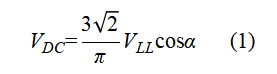
Where:
- V_DC= average DC output voltage (V)
- VLL= RMS line-to-line input voltage (V)
- α = thyristor firing angle (rad)
Equation (1) indicates that the output voltage can be regulated by adjusting the firing angle. Increasing the firing angle reduces the average DC voltage and consequently decreases the load current.
The DC-side current dynamics can be represented by [4][5]

Where:
- L = DC-side inductance (H)
- R = load resistance (Ω)
- i_DC = DC output current (A)
- V_DC= average DC output voltage (V)
The inductor stores energy and smooths the current waveform, thereby reducing current ripple generated by the converter switching process.
IV. PLECS Model Development
The converter model was developed using PLECS Standalone. The electrical subsystem contains the three-phase source, line inductances, SCR bridge, DC inductor, and resistive load.
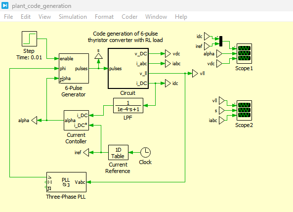
Figure 2: Code generation of 6-pulse thyristor converter with RL load Model in PLECS Simulation
Figure 2 presents the code generation model of the three-phase 6-pulse thyristor converter with an RL load developed in PLECS Simulation. The model consists of a three-phase AC source, source-side inductances, a six-thyristor bridge rectifier, and a DC-side RL load. The converter is controlled through a closed-loop current control system that adjusts the thyristor firing angle according to the reference current demand. The subsystem containing the power circuit is configured as an atomic subsystem to enable automatic ANSI-C code generation using PLECS Coder. This model serves as the foundation for validating the accuracy of generated code against the native PLECS simulation environment and demonstrates the workflow required for real-time simulation applications.
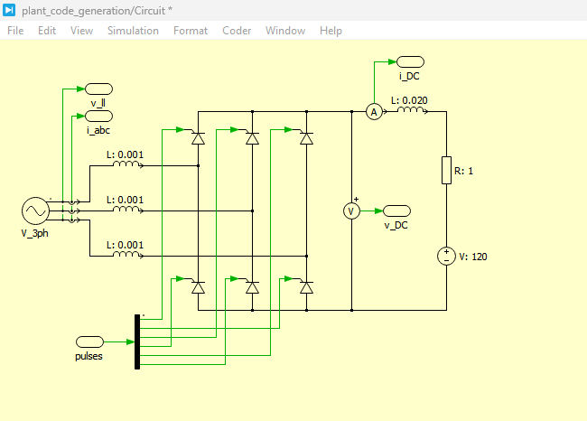
Figure 3: Plant Code generation Circuit in PLECS Simulation
You can download the Project files here: Download files now. (You must be logged in).
Figure 3 illustrates the plant code generation circuit implemented in PLECS Simulation. In this configuration, the electrical subsystem is executed using automatically generated ANSI-C code rather than native PLECS electrical components. The generated code represents the complete converter plant dynamics, including switching behavior, source inductances, and load characteristics. This approach enables efficient execution of the power electronic model in real-time environments such as Hardware-in-the-Loop (HIL) systems and RT Box platforms. The figure highlights the integration of the control algorithm, phase-locked loop (PLL), pulse generation block, and generated plant model, allowing direct comparison between standard simulation and code-generated execution modes.
A hierarchical subsystem named “Circuit” was created to encapsulate the entire electrical network. This subsystem was later designated as an atomic unit to enable code generation.
The control section includes several functional blocks:
A. Current Reference Generator
A current reference profile was implemented to evaluate dynamic performance. Initially, the reference current was set to zero amperes. At 10 ms, the reference increased gradually to 10 A over a period of 20 ms. At 60 ms, the reference was further increased to 25 A.
B. Current Controller
The controller continuously compares the measured DC current with the desired reference current. The resulting error signal is processed to determine the appropriate firing angle for the SCR bridge.
C. Phase-Locked Loop
A three-phase PLL synchronizes the controller with the AC source voltage. Accurate synchronization is essential because firing pulses must be generated at precise phase angles relative to the supply waveform [6].
D. Pulse Generation Unit
The pulse generator receives the calculated firing angle and phase information from the PLL. Six synchronized gate signals are generated to trigger the thyristors according to the required conduction sequence.
V. Code Generation Procedure
One of the primary objectives of this work was to evaluate the code generation capability of PLECS Coder.
The process begins by enabling the “Code Generation” option within the execution settings of the Circuit subsystem. Activating this feature automatically configures the subsystem as an atomic model, ensuring that the entire electrical network is treated as a single computational unit during code generation [7].
After enabling code generation, the subsystem becomes available within the Coder Options configuration menu. Several code generation parameters can then be adjusted, including:
- Discretization step size
- Code optimization options
- Output directory
- Numerical solver settings
PLECS Coder generates two primary files:
- Header file (.h)
- Source implementation file (.c)
These files contain ANSI-C representations of the electrical system and can be integrated directly into real-time simulation frameworks or embedded applications.
The generated code follows a standardized application programming interface (API), facilitating deployment on hardware-in-the-loop platforms and digital control systems.
VI. Discretization Analysis
Discretization is a critical step in converting continuous-time electrical systems into executable real-time models.
A discrete model approximates the behavior of the original system at specific sampling intervals. While larger sampling periods reduce computational burden, they may introduce numerical inaccuracies and degrade simulation fidelity [8].
Two discretization step sizes were investigated:
A. Step Size of 1×10⁻³ s
The first experiment employed a discretization interval of 1 ms.
After generating ANSI-C code and executing the model in CodeGen mode, noticeable deviations from the baseline simulation were observed. Significant discrepancies appeared in:
- DC current response
- Firing angle behavior
- Output voltage waveform
The generated-code simulation failed to accurately reproduce the transient behavior of the original model.
These deviations occur because the converter switching events and current dynamics evolve more rapidly than the selected sampling interval can accurately capture.
B. Step Size of 1×10⁻⁴ s
The discretization interval was subsequently reduced to 100 μs.
Following code regeneration and simulation, a substantial improvement in accuracy was observed. The generated-code response closely matched the baseline simulation throughout both transient and steady-state operating conditions.
The reduced sampling interval enabled more accurate representation of:
- Thyristor switching events
- Current dynamics
- Voltage variations
- Control system responses
Consequently, the generated-code model achieved near-identical performance to the original PLECS implementation.
VII. Simulation Results
Simulation studies were conducted to compare the native PLECS model and generated-code implementation.
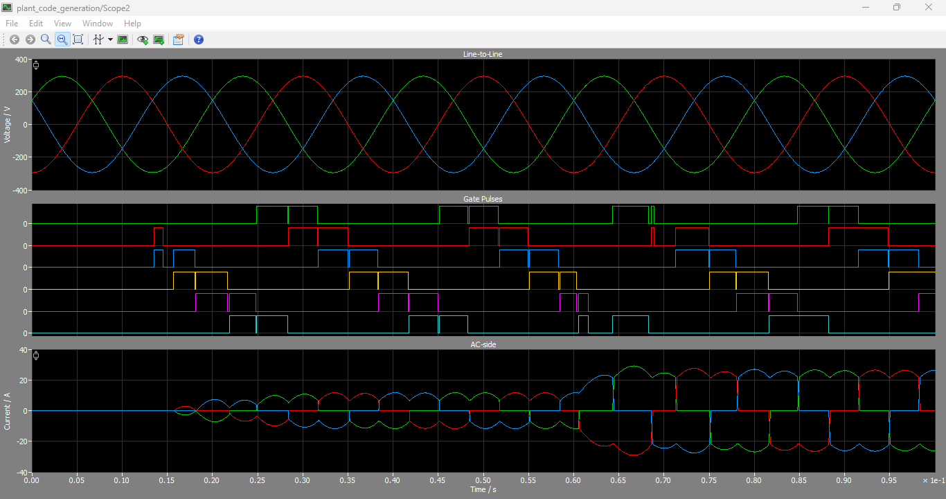
Figure 4: AC Side Line to Line three phase voltages, Gate pulses and AC currents graphs generated in PLECS Simulation
You can download the Project files here: Download files now. (You must be logged in).
Figure 4 shows the AC-side electrical characteristics of the three-phase 6-pulse thyristor converter, including line-to-line voltages, gate pulses, and three-phase input currents generated in PLECS Simulation. The line-to-line voltage waveforms exhibit balanced three-phase sinusoidal behavior, providing the input power source for the converter. The gate pulse signals indicate the firing sequence of the six thyristors, synchronized with the AC supply through the PLL-based control system. The three-phase input currents demonstrate the converter’s interaction with the AC source and exhibit the characteristic non-sinusoidal waveform associated with controlled rectifier operation. These results confirm proper synchronization between the firing circuit and supply voltages while illustrating the current distortion typically produced by line-commutated converters.
The following variables were monitored:
- DC current
- Reference current
- Firing angle
- DC voltage
A. DC Current Response
Initially, the DC current remained near zero because the reference signal was zero amperes.
At 10 ms, the reference current began increasing toward 10 A. The controller responded by reducing the firing angle and increasing converter output voltage.
At 60 ms, the current reference increased to 25 A, producing another transient response. The generated-code model with a discretization step size of 1×10⁻⁴ s accurately tracked these reference changes.
The measured current waveform exhibited a low-frequency ripple component characteristic of six-pulse rectifier operation [9].
B. Firing Angle Response
The firing angle varied dynamically according to load requirements.
When current demand increased, the controller reduced the firing angle to increase converter output voltage. Conversely, when current demand decreased, the firing angle increased.
Comparison of simulation traces showed excellent agreement between the native model and generated-code implementation for the 100 μs discretization interval.
C. DC Voltage Characteristics
The DC output voltage varied according to firing angle adjustments.
The generated-code simulation accurately reproduced the voltage waveform observed in the baseline model. Minor deviations were present but remained within acceptable limits for real-time simulation applications.
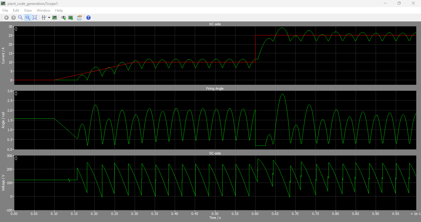
Figure 5: DC Side Currents, Firing angle and DC side Voltage output graphs generated by PLECS Simulation
You can download the Project files here: Download files now. (You must be logged in).
Figure 5 presents the DC-side performance of the converter, including the output current, firing angle, and DC output voltage waveforms obtained from PLECS Simulation. The DC current waveform follows the reference current profile generated by the controller, demonstrating effective current regulation during transient and steady-state operating conditions. The firing angle waveform varies dynamically as the controller adjusts the SCR triggering instants to maintain the desired output current. Simultaneously, the DC output voltage changes according to the firing angle variations, reflecting the controllable nature of the thyristor rectifier. The results verify the successful operation of the closed-loop control system and demonstrate the capability of the generated-code model to accurately reproduce converter dynamics and load responses.
D. Accuracy Assessment
Visual comparison of simulation traces revealed that the 100 μs discretization interval provided strong correlation with the baseline simulation.
The 1 ms discretization interval produced significant errors and therefore cannot be considered suitable for accurate real-time representation of the converter.
VIII. Real-Time Simulation Implications
Real-time simulation requires all computations to be completed within a fixed execution interval. Therefore, simulation fidelity must be balanced against computational efficiency.
Generated ANSI-C code offers several advantages:
- Faster execution
- Reduced computational overhead
- Hardware portability
- HIL compatibility
- Embedded deployment capability
However, selecting an excessively large discretization interval can compromise model accuracy. The results of this study demonstrate that careful tuning of the sampling interval is necessary to maintain acceptable fidelity [10].
The generated-code approach enables deployment of converter models onto real-time simulators such as RT Box systems, facilitating controller validation and system testing without requiring physical hardware.
IX. Discussion
The findings of this work demonstrate the practicality of automatic code generation for power electronic systems.
The generated-code implementation successfully reproduced the behavior of the native PLECS model when an appropriate discretization interval was selected.
Several important observations emerged:
- Code generation significantly improves model portability.
- Real-time execution becomes feasible through discretization.
- Sampling interval selection strongly influences simulation accuracy.
- A 100 μs discretization interval provides excellent performance for the investigated converter.
- Generated ANSI-C code can serve as a foundation for HIL and rapid prototyping applications.
The study further highlights the importance of validating generated-code models against baseline simulations before deployment in real-time environments.
X. Conclusion
This paper presented the modeling, code generation, and validation of a three-phase 6-pulse thyristor converter using PLECS Coder. The converter was implemented using native PLECS components and subsequently transformed into ANSI-C code through the PLECS code generation framework.
Comparative simulations demonstrated that discretization plays a crucial role in determining model accuracy. A discretization step size of 1×10⁻³ s produced significant deviations from the baseline simulation, whereas a step size of 1×10⁻⁴ s yielded excellent agreement between generated-code and native-model results.
The generated ANSI-C implementation successfully reproduced converter dynamics, current regulation behavior, firing-angle control, and voltage responses. These findings confirm the suitability of PLECS Coder for developing real-time plant models for hardware-in-the-loop testing, rapid control prototyping, and embedded simulation applications.
Future work may investigate smaller discretization intervals, advanced numerical integration techniques, and deployment of the generated code on real-time simulation hardware platforms.
References
[1] N. Mohan, T. M. Undeland, and W. P. Robbins, Power Electronics: Converters, Applications, and Design, 3rd ed. Hoboken, NJ, USA: Wiley, 2003.
[2] M. E. Elbuluk and M. Kankam, “Real-time simulation of power electronic systems,” IEEE Transactions on Industry Applications, vol. 37, no. 5, pp. 1458–1464, 2001.
[3] Plexim GmbH, PLECS User Manual, Zurich, Switzerland, 2023.
[4] M. H. Rashid, Power Electronics Handbook, 4th ed. Oxford, U.K.: Butterworth-Heinemann, 2018.
[5] B. K. Bose, Modern Power Electronics and AC Drives. Upper Saddle River, NJ, USA: Prentice Hall, 2002.
[6] R. Teodorescu, M. Liserre, and P. Rodriguez, Grid Converters for Photovoltaic and Wind Power Systems. Hoboken, NJ, USA: Wiley, 2011.
[7] Plexim GmbH, “Plant Code Generation: Three-Phase 6-Pulse Thyristor Converter,” PLECS Demo Model Documentation, Version 4.5.1, 2023.
[8] K. J. Åström and B. Wittenmark, Computer-Controlled Systems: Theory and Design, 3rd ed. Upper Saddle River, NJ, USA: Prentice Hall, 1997.
[9] P. C. Sen, Principles of Electric Machines and Power Electronics, 3rd ed. Hoboken, NJ, USA: Wiley, 2013.
[10] A. Monti, F. Ponci, S. D’Arco, and A. Benigni, “Real-time modeling and simulation of power electronic systems,” IEEE Industrial Electronics Magazine, vol. 8, no. 2, pp. 24–38, 2014.
You can download the Project files here: Download files now. (You must be logged in).







Responses