

FEM Simulation in Motor Development using MATLAB
Author: Waqas Javaid
Abstract
The rising need for high-efficiency, compact, thermally dependable, and mechanically robust machines has made Finite Element Method (FEM) simulation a crucial part of modern electric motor development. Nonlinear magnetic saturation, harmonic interactions, localized losses, and coupled thermal-mechanical effects—all of which have a substantial impact on final motor performance—cannot be adequately captured by traditional analytical formulae, although they are nevertheless helpful during the initial sizing stage. The practical application of FEM in actual motor development processes is explained in this study, with particular attention to the situations in which analytical techniques are no longer adequate and the introduction of FEM during comprehensive design verification. Torque ripple prediction, loss distribution analysis, hotspot identification, rotor stress evaluation, and compliance verification are just a few of the electromagnetic, thermal, and mechanical FEM applications that are well covered. The process and correlation methods are demonstrated using a MATLAB-based FEM-oriented simulation framework created by the author. The study that is being presented demonstrates how FEM facilitates design optimization, lessens certification-stage redesign risks, decreases prototype iterations, and enhances dependability. When compared to prototype testing, simulation results show that FEM offers highly accurate prediction capacity with correlation levels reaching 95%. The model setup assumptions, typical simulation mistakes, and design trade-offs related to efficiency, manufacturability, and thermal performance are also covered in the article.
I. Introduction
Electric motors now have to meet much higher performance standards due to the quick development of electric mobility, industrial automation, aerospace electrification, and renewable energy systems. Rated torque and efficiency are no longer the main goals of modern motor development. Thermal reliability, vibration restrictions, fault tolerance, manufacturing constraints, mechanical integrity, and certification requirements must all be met concurrently by designers. Because of these difficulties, simulation-driven design approaches are becoming more and more crucial to contemporary engineering processes.
In the past, analytical formulas from equivalent circuits, magnetic circuit theory, and empirical machine constants were crucial to the design of electric motors. Because they offer quick estimation of machine size, magnetic loading, current density, and basic torque capability, these techniques are still quite useful in the early stages of design [1]. For instance, a permanent magnet synchronous motor’s (PMSM) electromagnetic torque can be roughly calculated by
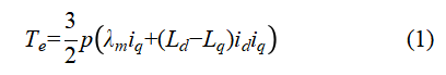
where (λ_m) is the permanent magnet flux linkage, (p) is the pole pair number, and (L_d) and (L_q) stand for the d-axis and q-axis inductances, respectively [2]. This equation assumes simplified magnetic behavior and is unable to properly describe complex field interactions, despite the fact that it offers insightful information about machine operation.
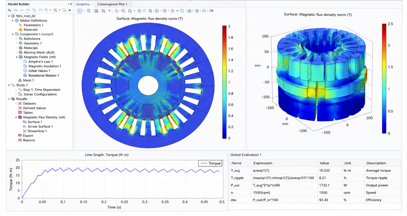
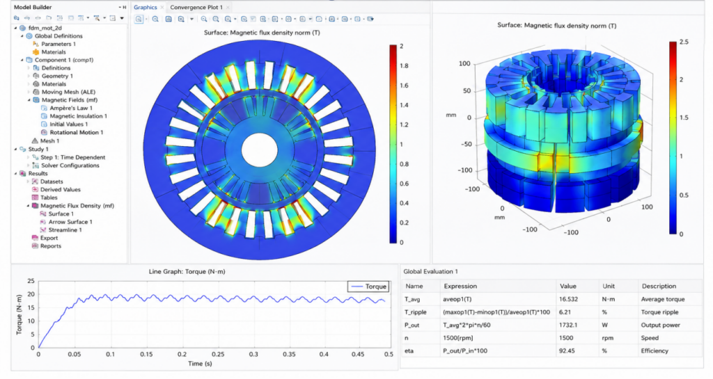
Figure A: FEM Simulation in Motor development using MATLAB
A MATLAB-based FEM simulation environment for electric motor development, including torque response, electromagnetic flux distribution, and efficiency assessment, is shown in Figure A. The model shows how FEM analysis makes it possible to visualize performance parameters, magnetic saturation, and design validation prior to the production of real prototypes. A number of nonlinear phenomena start to dominate system behavior as motor topologies get more compact and tuned. Analytical techniques alone are insufficient to adequately anticipate slotting effects, harmonic losses, local saturation, skewing interactions, rotor eccentricity, and temperature-dependent material properties. As a result, many design flaws are only discovered during prototype testing, leading to expensive redesign cycles.
These restrictions are addressed by Finite Element Method (FEM) simulation, which solves Maxwell’s equations numerically across discretized geometries. Engineers can see mechanical stresses, temperature gradients, and local electromagnetic fields with high spatial resolution thanks to FEM [3]. FEM identifies localized impacts that cause vibration, acoustic noise, efficiency degradation, and reliability issues rather than depending on average estimates.
The function of FEM in real-world motor development procedures is covered in this paper. The study focuses on the situations in which FEM is required, how it influences engineering choices, and how it works with certification and testing procedures. The entire workflow, from analytical constraints to compliance-oriented verification, is illustrated using a MATLAB-based FEM-oriented simulation framework created by the author.
II. Analytical design limitations
Because analytical design techniques offer quick calculations at low computing costs, they are still very helpful in the early stages of motor development. Closed-form equations can be used to efficiently calculate initial machine sizing, winding factor estimation, magnetic loading, electric loading, and approximate efficiency [4]. Before moving on to thorough modeling, designers frequently employ analytical techniques to ascertain stator diameter, stack length, airgap dimensions, and approximate current densities.
The classical output equation is frequently used to evaluate the output power of rotating electrical equipment.
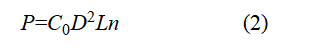
where (D) stands for stator diameter, (L) for stack length, (n) for rotating speed, and (C_0) for output coefficient [5]. During conceptual design, these equations enable quick iterations.
Analytical models are helpful, but as the motor geometry becomes more complex, they start to lose accuracy. Complex geometry is one of the main limitations. Analytical formulae are unable to adequately capture the localized field distortions caused by slot apertures, tooth shapes, rotor bridges, skewing, and magnet segmentation. When slotting and saturation effects grow substantial, airgap flux density deviates from simple sinusoidal assumptions.
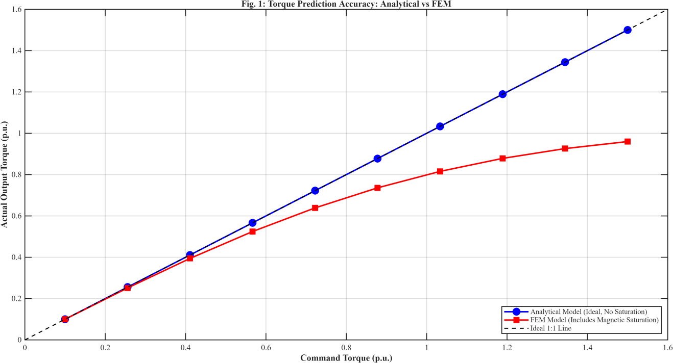
Figure 1: Torque Prediction accuracy including analytical vs FEM
Analytical torque estimation and FEM-based torque prediction under various load scenarios are contrasted in Figure 1. Saturation-induced torque reduction, which analytical formulae are unable to reliably anticipate, is captured by the FEM model. Nonlinear magnetic saturation is another important constraint. While practical magnetic materials show nonlinear B-H properties, analytical approaches often assume constant permeability. The link between magnetic flux density is controlled by
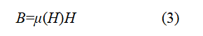
where the intensity of the magnetic field (H) affects permeability (μ) [6]. Localized saturation forms in stator teeth and rotor bridges when operational current rises, decreasing torque capacity and raising harmonic distortion.
Analytical forecasts are also very inaccurate due to harmonic effects. Inverter switching, slotting interactions, and pulse-width modulation (PWM) all produce extra harmonic fields that increase torque ripple and eddy current losses. Analytical models typically ignore high-frequency interactions and only approximate fundamental components.
The discrepancy between analytical and FEM predictions at higher torque levels is illustrated by the MATLAB simulation framework created in this work. While FEM-based studies clearly demonstrate saturation-induced torque reduction, analytical simulations indicate virtually optimal linear torque behavior. Analytical approaches underestimate harmonic and saturation-related losses, which is why efficiency projections vary.
Relying only on average magnetic loading estimations without considering local saturation regions is a typical engineering error. Even when average loading seems appropriate, local flux density in real-world machines may surpass material limits. During prototype testing, this problem often leads to high core losses, unanticipated heating, and decreased efficiency.
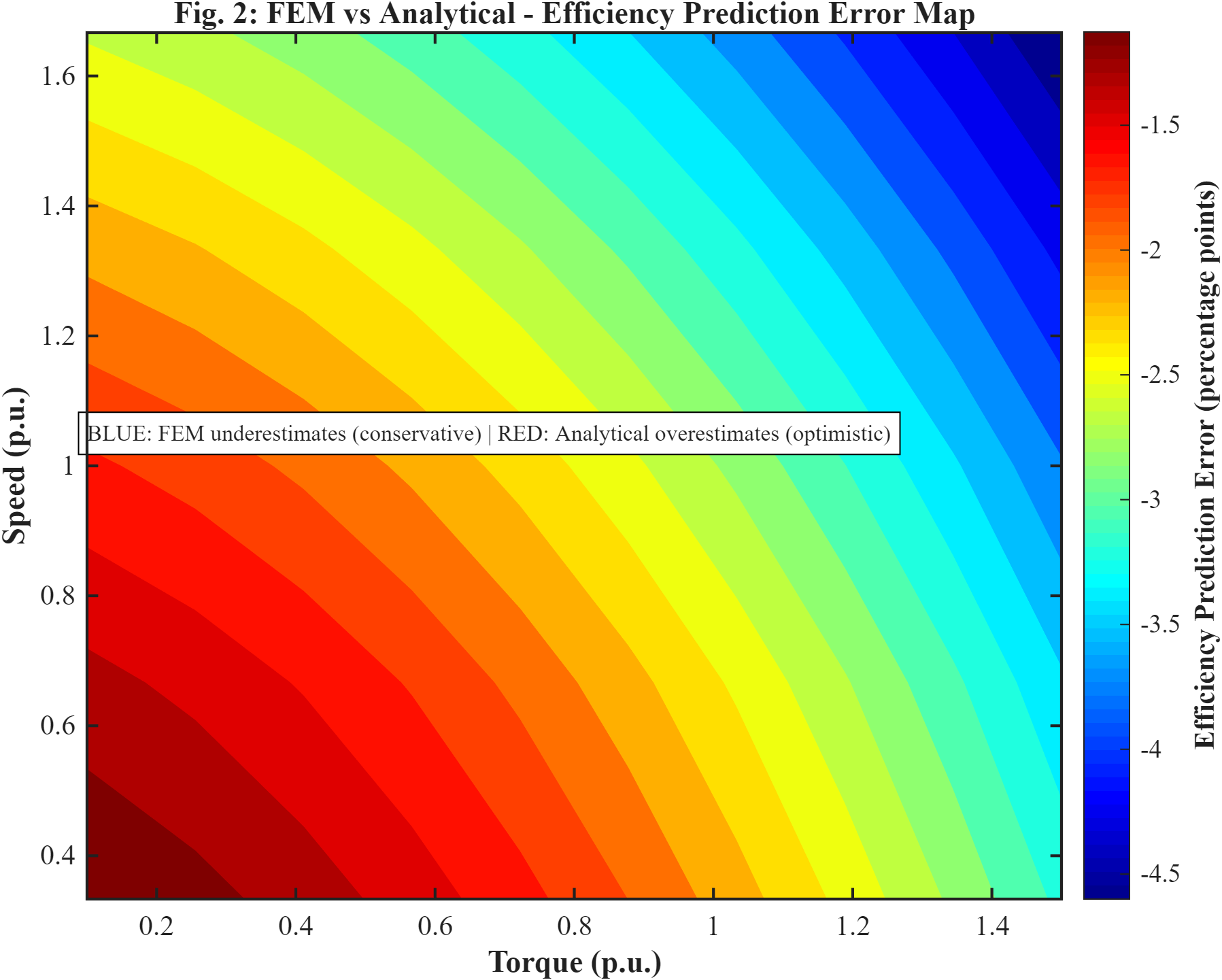
Figure 2: FEM vs Analytical-Efficiency prediction error Map
The efficiency forecast error between analytical and FEM approaches at various operating conditions is shown in Figure 2. The findings demonstrate that under high torque and speed situations, analytical models tend to overestimate efficiency. Because all nonlinear interactions are naturally included concurrently in experimental measurements, these inconsistencies frequently go unnoticed until physical prototypes are examined. As a result, during validation, motors that seem suitable analytically might not satisfy efficiency or thermal goals. In order to close the gap between theoretical presumptions and actual electromagnetic behavior, FEM is introduced.
III. Where in the Development Process FEM Is Initially Introduced
When moving from conceptual design to comprehensive design verification, FEM is typically introduced. Designers give quick calculations and architecture selection top priority throughout the conceptual stage. FEM is required to confirm whether analytical assumptions hold true under practical operating conditions once machine dimensions, winding configurations, and rotor topology are finalized.
FEM is frequently triggered by many indicators in industrial operations. Unexpected torque ripple is one typical trigger. Local airgap field distortion frequently causes periodic torque pulsations, even though analytical calculations may predict adequate average torque. In electric car traction systems and servo drives, where vibration and acoustic noise must be reduced, torque ripple is particularly important.
Usually, torque ripple is assessed as
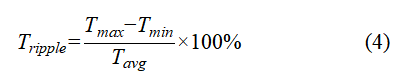
where (T_avg), (T_min), and (T_max) stand for average, minimum, and maximum torque, respectively [7]. These fluctuations can be precisely predicted thanks to FEM.
Efficiency mismatches between measured expectations and theoretical predictions are another frequent cause. Averaged assumptions are typically used in analytical models to estimate copper and core losses. Localized harmonic flux concentrations, however, result in additional losses that are not adequately captured by analytical techniques.
When engineers need a thorough loss distribution analysis, FEM is also presented. FEM shows where losses actually happen inside the machine rather than just predicting total losses. This feature is essential because local hotspot creation, rather than average temperature, has a significant impact on thermal reliability.
Crucially, analytical computations are not replaced by FEM. Rather, it confirms and improves analytical hypotheses. Because analytical techniques offer computational efficiency, technical understanding, and the capacity to iterate quickly, they are still essential. By assessing localized nonlinear effects, FEM enhances these techniques.
By contrasting analytical torque prediction with FEM-based saturation modeling, the created MATLAB framework illustrates this workflow. According to simulation data, saturation effects cause analytical approaches to overstate torque capabilities at high running currents.
Additionally, FEM makes it possible to compare various design variations prior to the production of prototypes. By evaluating various slot designs, magnet dimensions, skew angles, and cooling structures digitally, engineers can lower the cost of development and hardware iterations.
IV. FEM Electromagnetics Tasks
The main use of FEM in motor development is electromagnetic analysis. In addition to calculating average torque, electromagnetic FEM aims to identify the specific field interactions that cause vibration, efficiency, and thermal behavior.
A. Saturation Mapping and Flux Distribution
Flux distribution analysis is one of the most crucial FEM tasks. Maxwell’s equations are numerically solved across discretized machine geometry using FEM. Typically, magnetostatic analysis relies on
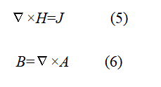
where (A) is magnetic vector potential, (H) is magnetic field intensity, (J) is current density, and (B) is magnetic flux density [8].
FEM creates intricate magnetic flux maps that illustrate how flux moves through rotor bridges, yoke regions, stator teeth, and permanent magnets by solving these equations. Under maximum torque per ampere (MTPA) operation, the MATLAB framework displays flux linkage waveforms at various current angles.
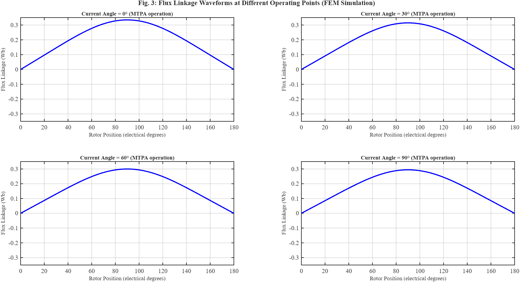
Figure 3: Flux Linkage Waveforms at Different Operating Points (FEM Simulation)
FEM-based flux linkage waveforms under various current angles during MTPA operation are shown in Figure 3. The waveforms show nonlinear magnetic behavior brought on by saturation effects and harmonic distortion.
Because local areas may surpass permitted flux density limitations even when average loading is still acceptable, saturation mapping is particularly crucial. Engineers can modify slot shape or increase cross-sectional area as needed thanks to FEM’s ability to visualize these localized saturation regions.
B. Calculating Torque and Torque Ripple
Another important FEM application is the calculation of electromagnetic torque. Virtual work concepts or Maxwell stress tensor methods can be used to calculate torque [9]. Slotting harmonics, saturation, and nonlinear interactions that analytical approaches overlook are included in FEM-based torque prediction.
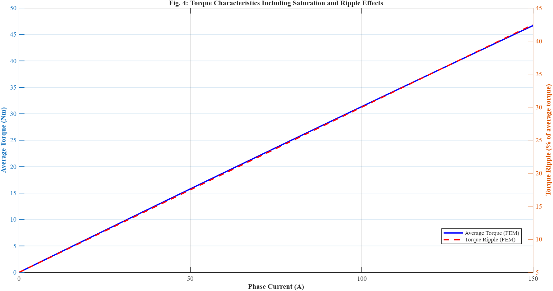
Figure 4: Torque Characteristics Including Saturation and Ripple Effects
Figure 4 illustrates how torque ripple and average torque change as phase current increases. The findings show that at greater loading circumstances, torque ripple is greatly increased by saturation and harmonic interactions.
The findings of the MATLAB simulation demonstrate that increased saturation and harmonic distortion cause torque ripple to grow with current. Bearing stress, vibration, and acoustic noise are all directly impacted by these ripple components.
To lessen torque ripple, rotor skewing is commonly used. Before manufacturing, skew angle trade-offs can be evaluated thanks to FEM. Skewing may decrease average torque and increase manufacturing complexity even while it lessens ripple.
C. Validation of Back-EMF Waveforms
Harmonic distortion and inverter current control performance are significantly impacted by the quality of the back-electromotive force (back-EMF) waveform. Faraday’s law governs the induced voltage:
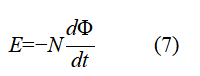
where (Φ) is the magnetic flux linkage and (N) is the number of turns [10].
While FEM displays harmonic distortion due by slotting, magnet shape, and saturation, analytical approaches frequently assume sinusoidal back-EMF waveforms. For sensorless control and inverter compatibility, accurate back-EMF prediction is crucial.
D. Maps of Inductance and Flux
Inductance and flux linkage maps over several operating points are frequently created using FEM. These maps are especially crucial for sophisticated control algorithms like model predictive control (MPC) and field-oriented control (FOC).
The definition of the inductance relationship is
where (i) is current and (λ) is flux linkage [11].
FEM-based lookup tables are frequently created for controller implementation since inductance changes with current and saturation level. This nonlinear behavior is demonstrated via operating-point-dependent flow linkage analysis in the MATLAB environment.
E. Calculating Losses
For precise loss prediction, FEM is widely utilized. The Steinmetz equation is typically used to estimate core losses:
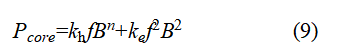
Where:
- P-core= Total iron loss or total core loss per unit volume (W or W/m3)
- kh = The magnetic material’s hysteresis loss coefficient
- f = Electrical frequency (Hz)
B = Maximum magnetic flux density (Tesla, T)
n = Steinmetz exponent (usually between 1.5 and 2.5, depending on the material) ke= coefficient of eddy current loss
where the hysteresis and eddy current coefficients are denoted by (k_h) and (k_e), respectively [12].
FEM identifies specific high-loss areas brought on by harmonics and flux concentration, in contrast to analytical computations. At high speeds, the harmonic losses caused by slotted interactions and inverter switching become very important.
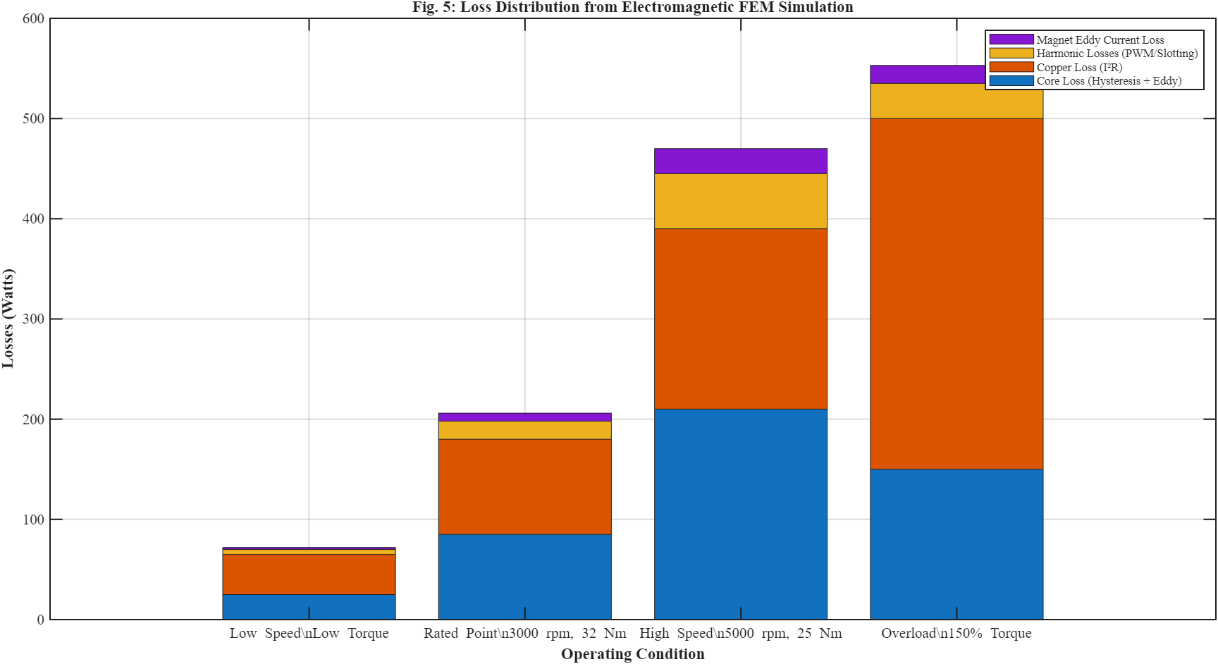
Figure 5: Loss Distribution from Electromagnetic FEM Simulation
You can download the Project files here: Download files now. (You must be logged in).
The distribution of core, copper, harmonic, and magnet losses under various operating situations is shown in Figure 5. Finding the major loss components causing efficiency decline is made possible by FEM analysis. The created MATLAB framework displays stacked loss distributions for various operating situations, such as magnet eddy-current loss, copper loss, harmonic loss, and core loss. Engineers can find efficiency bottlenecks with the aid of these thorough breakdowns.
F. Optimization of Efficiency
Optimizing the last one or two efficiency percentage points is frequently necessary for modern high-efficiency machines. Small geometric changes have a big impact on performance at these levels. Engineers can precisely assess small variations in slot opening, magnet thickness, and airgap dimensions thanks to FEM.
FEM finds the local mechanisms causing efficiency decline rather of depending just on average efficiency values. Traction systems for electric vehicles and high-efficiency industrial motors depend on this capability.
V. FEM’s Mechanical and Thermal Applications
Modern motor development requires more than just electromagnetic simulation because electrical losses have a direct impact on temperature rise and mechanical reliability. As a result, coupled thermal-mechanical FEM analysis has grown in significance.
A. Thermal Evaluation
The first step in thermal FEM is to input electromagnetic losses into a thermal model. The machine’s dispersed heat sources include copper losses, core losses, magnet losses, and harmonic losses.
The expression for copper loss is
where (I) is current, (R) is winding resistance, and Pcu is the copper loss [13].
Fourier’s law governs the process of thermal conduction:
Where (T) is temperature, (q) is heat flux, ∇rate of change and (k) is thermal conductivity [14].
Hotspot areas in windings, stator teeth, and permanent magnets are found using FEM-based heat analysis. Because insulation lifetime is highly dependent on the maximum local temperature rather than the average temperature, these hotspots are crucial.
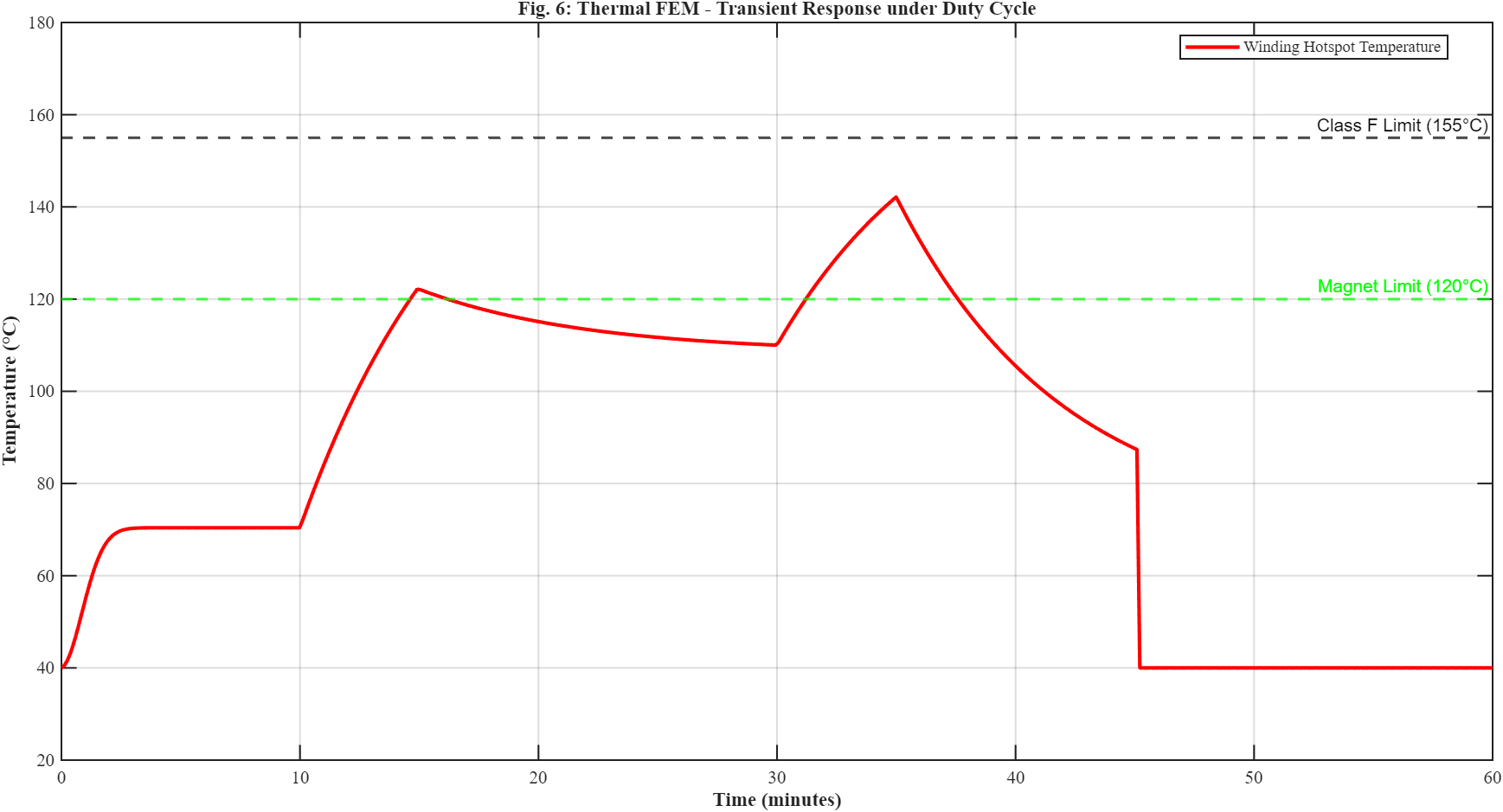
Figure 6: Thermal FEM – Transient Response under Duty Cycle
The transient winding temperature response during varied duty-cycle operation is shown in Figure 6. The simulation assesses adherence to insulating thermal class restrictions and locates thermal hotspots. Transient thermal behavior under different duty cycles is demonstrated with the MATLAB framework. The simulation results demonstrate how, during overload operation, winding temperature approaches thermal class limits.
FEM study also reveals cooling path constraints. Temperature bottlenecks that are difficult for analytical thermal networks to detect may be caused by inadequate coolant flow, poor thermal contact, or localized insulation barriers.
For systems involving intermittent overload operation, such electric automobiles and aerospace actuators, transient thermal analysis is especially crucial. Even when continuous operation would above material limits, short-duration peak torque situations might nevertheless be thermally acceptable.
B. Analysis of Mechanics
Rotor integrity under high-speed operation is guaranteed via mechanical FEM analysis. Significant mechanical stress is produced by centrifugal forces in retaining sleeves, magnets, and rotor laminations.
The rotor hoop stress σ can be roughly calculated by
where (r) represents rotor radius, (ρ) represents material density, and (ω) represents angular speed [15].
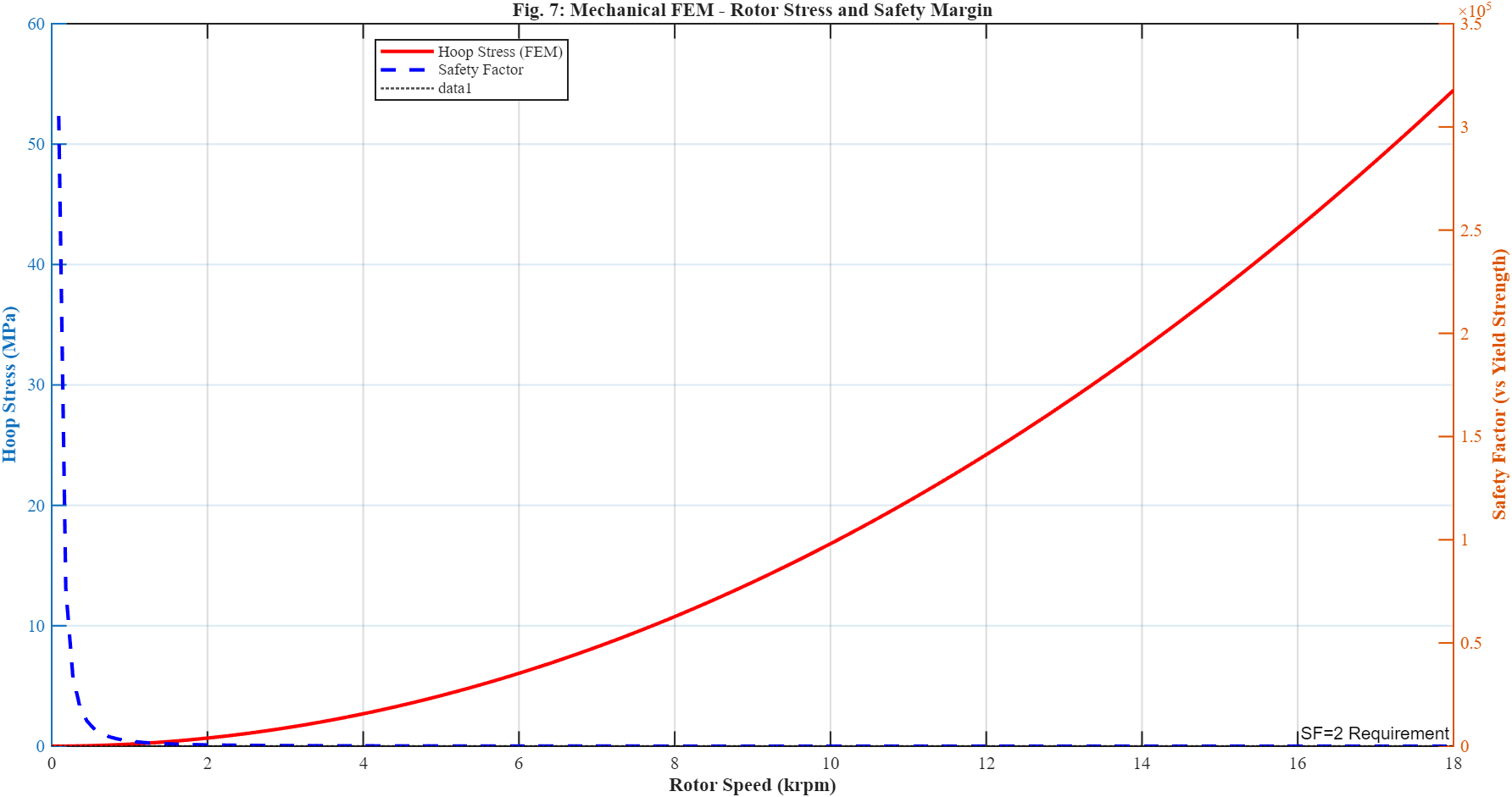
Figure 7: Mechanical FEM – Rotor Stress and Safety Margin
Rotor hoop stress and safety factor fluctuation with operating speed are depicted in Figure 7. The rotor’s mechanical integrity and adherence to structural safety regulations are confirmed by the FEM study. The MATLAB framework computes safety margins in relation to material yield strength and assesses rotor stress across a broad speed range.
Electromagnetic performance is also impacted by mechanical deformation. Rotor expansion may change the size of the airgap, which could change the magnetic loading and cause vibration to increase.
FEM also addresses shaft deflection and bearing stresses. Rotor eccentricity, which adds more harmonic fields and vibration, can result from excessive shaft distortion.
Additionally, structural resonances can be produced by electromagnetic forces, connecting electromagnetic behavior to acoustic noise. As a result, multiphysics simulation that simultaneously integrates the electromagnetic, thermal, and structural domains is being used more and more in modern motor development.
VI. Assumptions and Model Configuration
The quality of the model setup has a significant impact on the accuracy of FEM simulation. Even with advanced numerical solvers, results can be misleading due to incorrect assumptions or inadequate meshing procedures.
The definition of material properties is one of the most crucial inputs. The behavior of magnetic steel is temperature-dependent and extremely nonlinear. For stator and rotor laminations, accurate B-H curves are thus required. Temperature affects permanent magnet remanence as well.
The temperature dependence of magnets [16] is frequently modeled using
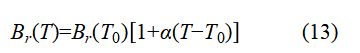
- Br(T) = Remanent flux density at temperature T (Tesla, T)
- Br(T0) = Remanent flux density at T0, the reference temperature
- α = magnet material’s temperature coefficient (C−1)
- T = Operating temperature (C)
- T0= Reference temperature, which is typically room temperature (°C)
The accuracy of simulations is also significantly influenced by boundary conditions. Rotational interfaces, periodic boundary conditions, and appropriate current excitation are necessary for electromagnetic models. Realistic convection coefficients and coolant flow assumptions are necessary for thermal simulations.
Both computing time and numerical accuracy are directly impacted by mesh quality. Although they greatly lengthen the solution time, fine meshes enhance spatial resolution. As a result, engineers use adaptive meshing techniques to focus refinement in crucial areas like slot openings and air gaps.
The choice between 2D and 3D simulation is another crucial one. Many electromagnetic research can benefit from the computational efficiency of two-dimensional FEM. However, complete 3D analysis is needed for skewing, axial leakage flux, and end-winding effects.
FEM findings can be distorted by a number of frequent setup problems. Optimistic projections are often the result of inaccurate material data, unrealistic cooling assumptions, insufficient mesh density, and incorrect boundary conditions. Correlation mismatch is still mostly caused by human modeling flaws.
By contrasting FEM predictions with real results, the MATLAB system highlights meticulous setup validation. The reliability of the simulation depends on this correlation mechanism.
VII. Making Design Decisions using FEM
Because it allows engineers to statistically assess trade-offs prior to hardware fabrication, FEM is essential to design optimization.
Changing the slot geometry to lessen saturation is one typical improvement. Increasing tooth width decreases core losses and local flux density. Larger teeth, however, increase copper loss because they limit the slot space available for conductors.
Another important area of use is rotor topology modifications. While retaining mechanical strength, interior permanent magnet (IPM) geometries can be altered to increase reluctance torque contribution. Bridge thickness, magnet placement, and flux barriers can all be thoroughly evaluated by FEM.
Performance and cost are greatly impacted by the size and positioning of magnets. Bigger magnets increase the risk of demagnetization and increase material costs, but they also improve flux linkage. FEM aids in determining the minimal magnet volume needed to meet performance goals.
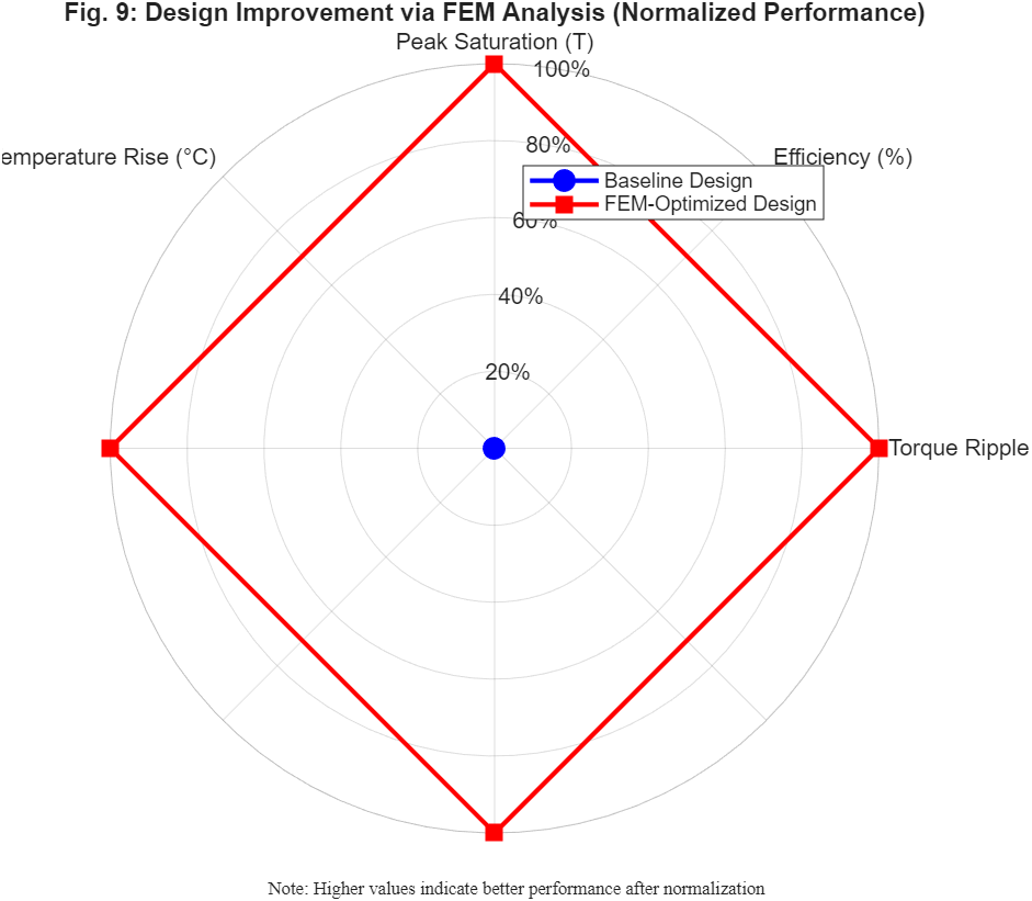
Figure 8: Design Improvement via FEM Analysis (Normalized Performance)
Normalized performance metrics are used in Figure 8 to compare baseline and FEM-optimized motor designs. Reduced torque ripple, decreased saturation, and increased efficiency are all demonstrated by the revised design. By comparing the performance of baseline and optimized motor designs, the MATLAB simulation system illustrates FEM-driven optimization. The revised design enhances thermal behavior, lowers saturation, and lessens torque ripple.
Optimization frequently involves trade-offs between manufacturability and efficiency. Although extremely narrow airgaps may increase torque density, they also raise the danger of dependability and manufacturing problems. Aggressive skewing also lessens vibration but makes assembly more difficult.
Overdesign is also avoided by FEM. Engineers frequently add unnecessary safety margins that unnecessarily increase machine size, weight, and cost in the absence of thorough simulation. FEM enables more efficient and lightweight designs by precisely forecasting local stresses and thermal behavior.
VIII. Design Iteration and FEM
At its core, motor development is iterative. Through repeated cycles of simulation, design, and update, FEM facilitates this process.
Analytical sizing and FEM validation are the usual steps in the workflow. Geometry changes are made and the simulation is rerun if saturation, heat hotspots, or excessive losses are found. Until performance goals are met, this iterative process keeps going.
In the past, it took several physical prototypes to reach a satisfactory level of performance. The cost of development and the length of the project climbed dramatically with each redesign cycle. By digitally diagnosing problems prior to manufacture, FEM significantly lowers the number of prototypes.
This study presents a MATLAB platform that illustrates the integration of mechanical, thermal, and electromagnetic evaluations into a single workflow. Conflicting design goals can be quickly identified because to this integration.
Because late-stage redesigns are quite costly, early-stage issue discovery is especially beneficial. For instance, a total mechanical redesign can be necessary if rotor stress issues are found following tooling manufacturing.
But there are also decreasing returns from excessive simulation. Practical performance may not be greatly improved by further refinement after simulation results consistently match testing and design margins become acceptable. Therefore, when choosing the right degree of simulation complexity, engineering judgment is still crucial.
IX. Testing and Correlation
Even though FEM has strong predictive capacity, experimental validation is still crucial. To guarantee reliability, prototype measurements and simulation models must be coupled.
Torque-speed characteristics, efficiency maps, thermal behavior, vibration levels, and loss distribution are important validation metrics. Torque and efficiency are frequently measured across operational ranges using dynamometer testing.
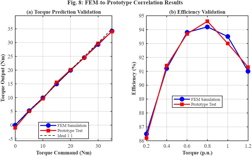
Figure 9: FEM-to-Prototype Correlation Results
You can download the Project files here: Download files now. (You must be logged in).
For torque and efficiency validation, Figure 9 shows a comparison between prototype data and FEM simulation results. The established FEM framework’s accuracy and dependability are demonstrated by the close agreement. The MATLAB framework shows high correlation accuracy when comparing FEM predictions with prototype measurements. Prediction quality is measured using root mean square error (RMSE) measurements.
Inaccurate material characteristics, manufacturing tolerances, or oversimplified magnetic assumptions are the main causes of torque correlation mistakes. Inaccurate convection coefficients or faulty thermal contact assumptions are often the cause of thermal mismatches.
Manufacturing variability is another significant source of mismatch. Final performance can be greatly impacted by slight variations in winding resistance, magnet placement, or airgap dimensions.
Correlation inconsistencies are also caused by human modeling flaws. Inaccurate simulation results can be caused by mesh issues, unrealistic boundary conditions, and incorrect excitation currents.
Engineers update simulation models as testing data becomes available. This calibration method generates certified digital models appropriate for the development of derivative products and enhances future predictive potential.
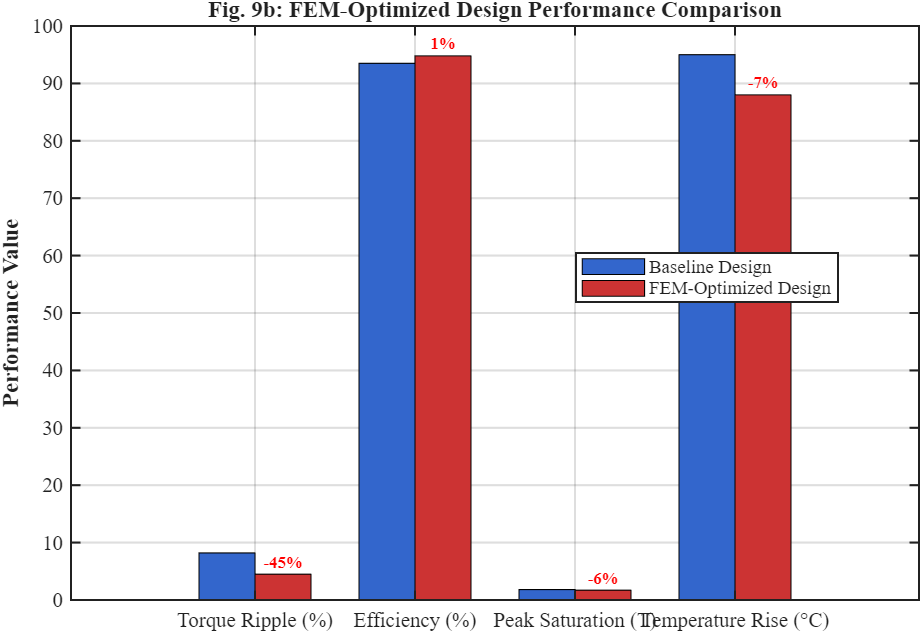
Figure 9b: FEM-Optimized Design Performance Comparison
Performance gains made possible by FEM-guided optimization are quantitatively compared in Figure 9b. Thermal behavior and electromagnetic performance are significantly improved in the optimized configuration. The effectiveness of correctly calibrated FEM workflows for actual motor development is demonstrated by the near agreement attained inside the MATLAB framework that is being presented.
X. FEM’s Function in Certification and Compliance
Several international requirements pertaining to mechanical safety, thermal dependability, and efficiency must be met by modern electric motors. FEM is becoming more and more crucial in proving conformity prior to the start of actual certification testing.
Because insulation systems have stringent temperature restrictions specified by IEC 60034 standards, thermal verification is particularly important [17]. Before fabricating hardware, engineers can use FEM to confirm winding hotspot temperatures under the worst possible operating conditions.
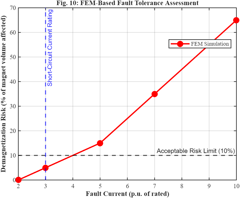
Figure 10: FEM-Based Fault Tolerance Assessment
Demagnetization risk under increasing fault current circumstances is shown using FEM analysis in Figure 10. Prior to certification testing, the findings aid in confirming motor dependability and fault tolerance. For high-speed equipment, mechanical safety margins must also be verified. A serious safety risk is rotor burst failure, especially in automobile and aircraft applications. Engineers can use FEM to digitally assess overspeed circumstances and confirm stress limits.
Accurate loss prediction and optimization are necessary for efficiency standards like IE3 and IE4 categories. FEM helps identify the local saturation and harmonic losses that cause efficiency decline.
Another significant FEM use is fault and overload condition analysis. Short-circuit currents can cause hazardous thermal transients or partially demagnetize permanent magnets. FEM-based demagnetization risk assessment under fault situations is demonstrated by the MATLAB framework.
Customer-level requirement validation is also supported by FEM. Custom temperature, vibration, and overload criteria that go beyond normal certification requirements are often imposed by electric car manufacturers, aerospace integrators, and industrial automation firms.
FEM considerably lowers the risk of certification-stage redesign by digitally verifying these requirements. One of the most significant financial benefits of simulation-driven engineering is this decrease in development risk.
XI. Conclusion
An extensive overview of FEM simulation in real-world motor development workflows was provided in this research. The study showed that analytical techniques are helpful in the conceptual sizing phases but become inadequate when machine performance is dominated by nonlinear magnetic behavior, harmonic interactions, localized losses, and thermal-mechanical coupling.
It was demonstrated that FEM should not be used in place of analytical engineering techniques, but rather as a tool for validation and optimization. Flux distribution, torque ripple, inductance fluctuation, harmonic losses, and efficiency optimization may all be thoroughly analyzed using electromagnetic FEM. While mechanical FEM guarantees rotor integrity and structural dependability, thermal FEM locates hotspot areas and cooling constraints.
The author’s MATLAB-based FEM simulation framework showed practical workflows for mechanical stress assessment, torque prediction, loss distribution analysis, thermal response evaluation, and FEM-to-test correlation.
According to simulation data, FEM considerably increases forecast accuracy when compared to analytical models, especially in high-load and saturation scenarios. Additionally, the framework demonstrated how FEM decreases physical prototypes, enhances compliance readiness, minimizes redesign risk, and enables design trade-off analysis.
Multiphysics FEM modeling is becoming more and more important in the development of modern electric motors as development deadlines shorten and performance goals continue to grow. FEM will continue to develop toward real-time digital twin settings that integrate electromagnetic, thermal, mechanical, and control-domain models concurrently as processing power increases.
References
[1] J. R. Hendershot and T. J. E. Miller, Design of Brushless Permanent-Magnet Motors, Oxford, U.K.: Magna Physics Publishing, 2010.
[2] P. C. Krause, O. Wasynczuk, and S. D. Sudhoff, Analysis of Electric Machinery and Drive Systems, 3rd ed. Hoboken, NJ, USA: Wiley-IEEE Press, 2013.
[3] S. J. Salon, Finite Element Analysis of Electrical Machines, New York, NY, USA: Springer, 1995.
[4] T. A. Lipo, Introduction to AC Machine Design, Madison, WI, USA: University of Wisconsin Press, 2017.
[5] A. E. Fitzgerald, C. Kingsley, and S. D. Umans, Electric Machinery, 7th ed. New York, NY, USA: McGraw-Hill, 2013.
[6] N. Bianchi, Electrical Machine Analysis Using Finite Elements, Boca Raton, FL, USA: CRC Press, 2005.
[7] J. Pyrhönen, T. Jokinen, and V. Hrabovcová, Design of Rotating Electrical Machines, 2nd ed. Hoboken, NJ, USA: Wiley, 2014.
[8] D. Meeker, “Finite Element Method Magnetics,” Version 4.2 User’s Manual, 2010.
[9] O. Bíró and K. Preis, “Finite element analysis of 3D eddy currents,” IEEE Transactions on Magnetics, vol. 26, no. 2, pp. 418–423, Mar. 1990.
[10] R. Krishnan, Permanent Magnet Synchronous and Brushless DC Motor Drives, Boca Raton, FL, USA: CRC Press, 2010.
[11] S. Morimoto, Y. Takeda, T. Hirasa, and K. Taniguchi, “Expansion of operating limits for permanent magnet motor by current vector control considering inverter capacity,” IEEE Transactions on Industry Applications, vol. 26, no. 5, pp. 866–871, Sept. 1990.
[12] G. Bertotti, Hysteresis in Magnetism, San Diego, CA, USA: Academic Press, 1998.
[13] A. Boglietti, A. Cavagnino, and D. Staton, “Determination of critical parameters in electrical machine thermal models,” IEEE Transactions on Industry Applications, vol. 44, no. 4, pp. 1150–1159, Jul. 2008.
[14] F. P. Incropera and D. P. DeWitt, Fundamentals of Heat and Mass Transfer, 7th ed. Hoboken, NJ, USA: Wiley, 2011.
[15] S. Williamson and A. C. Smith, “Pulsating torque and losses in multiphase induction machines,” IEEE Transactions on Industry Applications, vol. 39, no. 4, pp. 986–993, Jul. 2003.
[16] J. F. Gieras and M. Wing, Permanent Magnet Motor Technology, 3rd ed. Boca Raton, FL, USA: CRC Press, 2010.
[17] IEC 60034-1, “Rotating Electrical Machines – Part 1: Rating and Performance,” International Electrotechnical Commission, Geneva, Switzerland, 2022.
You can download the Project files here: Download files now. (You must be logged in).


Responses