

Electric Motor Development Process from Design to Production Simulation in MATLAB

Author: Waqas Javaid
Abstract
This paper presents a comprehensive technical walkthrough of the electric motor development lifecycle, from initial design through prototyping, testing, and production. The paper addresses the practical engineering decisions and constraints encountered during motor development, including motor type selection based on application requirements, electromagnetic modeling methodologies, integration with power electronics and control systems, prototyping challenges, and validation procedures. Key aspects covered include material selection trade-offs, thermal management strategies, manufacturing constraints, and iterative optimization based on test results. The paper emphasizes practical engineering reasoning rather than theoretical derivations, providing actionable guidance for motor design engineers, power electronics specialists, and mechanical engineers. The development process is illustrated through systematic analysis of design parameters, simulation methods, control integration challenges, and testing protocols that ensure reliable motor performance in real-world applications.
I. Introduction
THE DEVELOPMENT of electric motors for modern applications requires a systematic approach that integrates electromagnetic design, mechanical engineering, thermal management, and control system integration [1]. Unlike theoretical motor design, which focuses primarily on electromagnetic principles, the practical development process must address real-world constraints including manufacturing tolerances, material availability, cost targets, and production scalability [2].
The electric motor development lifecycle typically follows a structured process: requirement analysis, motor type selection, electromagnetic design, prototyping, testing validation, and iterative refinement [3]. Each phase presents unique challenges that require trade-offs between competing objectives such as performance, efficiency, cost, and manufacturability [4].
This paper provides a practical engineering guide to the electric motor development process, focusing on the decisions and constraints encountered in real-world development programs. Section II discusses motor type selection and design parameter rationale. Section III covers electromagnetic modeling and simulation methods. Section IV addresses integration with control systems and power electronics. Section V examines prototyping challenges and manufacturing constraints. Section VI describes testing and validation procedures. Section VII discusses iterative optimization based on test feedback. Section VIII presents conclusions.
II. Concept of Electric Motor Design
A. Motor Type Selection Based on Application Requirements
The selection of motor topology represents the first major decision in the development process and fundamentally influences all subsequent design activities [5]. Table I summarizes the key characteristics of major motor types and their typical applications.
TABLE 1: MOTOR TYPE COMPARISON FOR DIFFERENT APPLICATIONS
| Motor Type | Torque Density | Efficiency | Cost | Control Complexity | Typical Applications |
| Induction Motor (IM) | Medium | Medium | Low | Low | Industrial drives, HVAC, pumps |
| PM Synchronous (PMSM) | High | High | High | Medium | EV traction, robotics, aerospace |
| Electrically Excited (EESM) | Medium-High | High | Medium | High | Heavy EV, trucks, buses |
| Synchronous Reluctance (SynRM) | Medium | High | Low-Medium | Medium | Industrial, compressors |
| BLDC Motor | High | High | Medium | Medium | Appliances, drones, tools |
For electric vehicle traction applications, PMSM offers superior torque density and efficiency, though at higher material cost due to rare-earth magnets [6]. Induction motors remain attractive for cost-sensitive industrial applications where efficiency requirements are less stringent. The selection must consider the torque-speed operating profile, with constant torque region at low speeds and constant power region at high speeds being characteristic of traction applications.
B. Core Design Parameters
The fundamental design parameters that define motor capability include rated torque, rated speed, peak torque, maximum speed, and continuous power rating [7]. The torque-speed envelope determines the motor’s ability to meet application demands:
The continuous torque rating is limited by thermal considerations, while peak torque is limited by magnetic saturation and inverter current capability. The constant power speed range (CPSR) indicates the motor’s ability to maintain power output at high speeds, typically ranging from 2:1 to 6:1 for traction motors.
C. Material and Winding Considerations
Material selection significantly impacts motor performance, cost, and manufacturability [8]. Electrical steel grade affects core losses, with high-grade steels (M235-35A) reducing losses by 30-50% compared to standard grades but at 2-3 times higher cost. Magnet selection involves trade-offs between remanence, coercivity, temperature stability, and cost. N52 magnets offer highest flux density but poor temperature stability, while N42SH provides better high-temperature performance.
Winding configuration choices include distributed windings (better flux distribution, lower torque ripple) versus concentrated windings (shorter end turns, lower copper loss, easier manufacturing). Hairpin windings enable high copper fill factors (55-60%) but require specialized manufacturing equipment.
D. Performance-Cost-Manufacturability Trade-offs
The development process must balance three competing objectives: performance, cost, and manufacturability [9]. High-performance designs using premium materials and tight tolerances achieve superior efficiency and torque density but increase material and manufacturing costs. Conversely, cost-optimized designs may use lower-grade materials and relaxed tolerances, accepting moderate performance reductions for significant cost savings.
The figure of merit for design trade-off analysis can be expressed as:
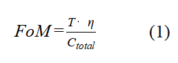
where T is torque, η is efficiency, and C_total represents total manufacturing cost. Optimal designs maximize this figure while meeting application-specific requirements.
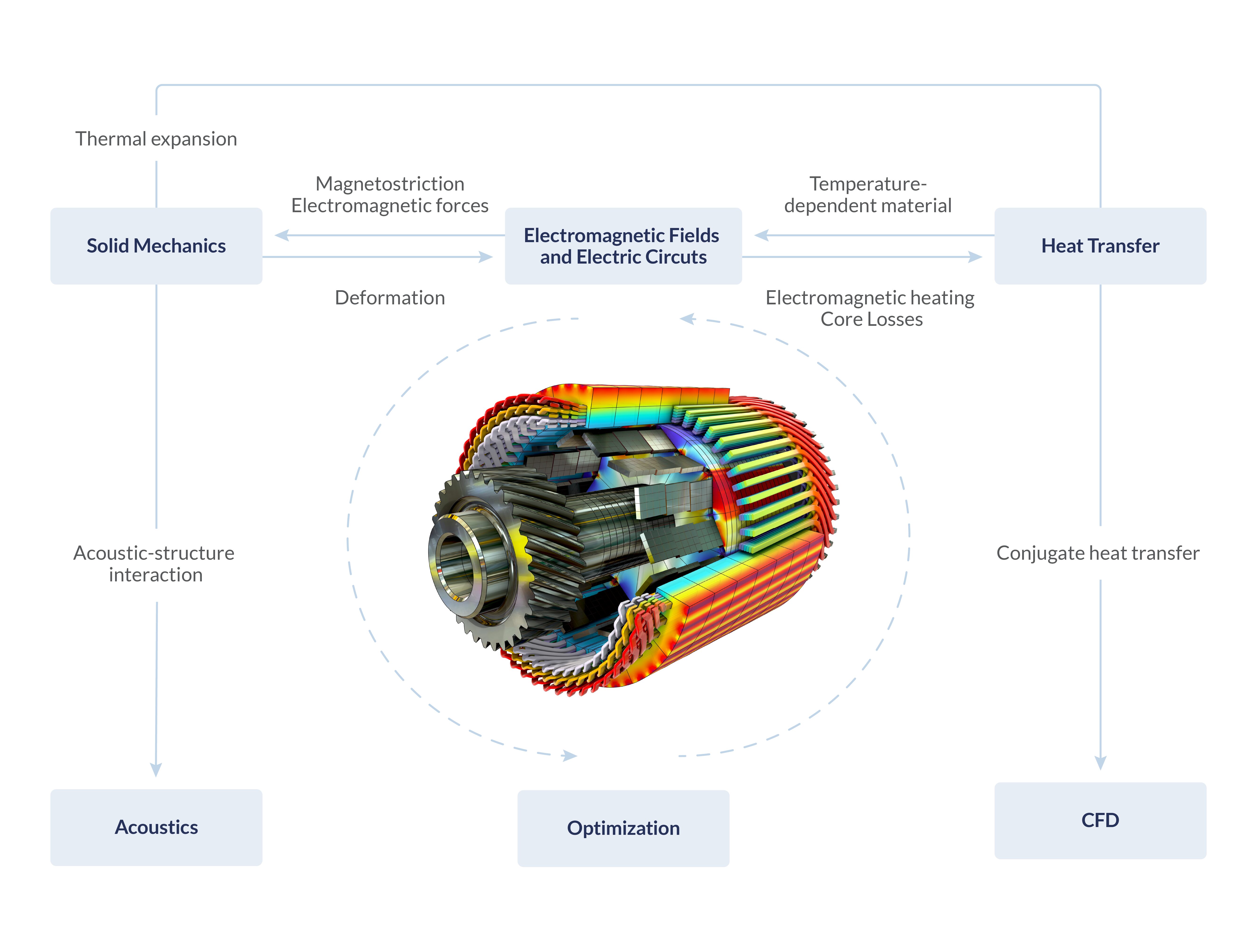
III. Electromagnetic Modeling and Simulation
A. Magnetic Circuit Analysis
Before committing to prototyping, electromagnetic modeling predicts motor behavior and identifies potential issues [10]. Magnetic circuit analysis provides rapid initial estimates of flux distribution, saturation levels, and inductance characteristics. The magnetic circuit is represented as a network of reluctances corresponding to different motor components:
The air gap reluctance dominates the magnetic circuit, making air gap length a critical design parameter. Reducing air gap increases flux density and torque capability but tightens manufacturing tolerances and increases cogging torque.
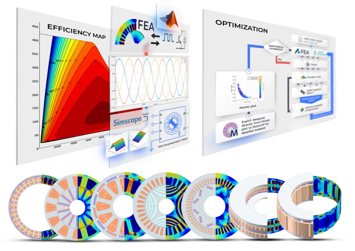
B. Finite Element Modeling for Performance Prediction
Finite Element Analysis (FEA) provides detailed field distribution information essential for accurate performance prediction [11]. Two-dimensional FEA suffices for most motor types, though three-dimensional analysis is required for end effects and skewed rotors. The FEA process involves:
- Geometry creation and meshing, with refinement in high-gradient regions
- Material property assignment including non-linear B-H curves
- Excitation definition with current waveforms and rotor position
- Solution of Maxwell’s equations for magnetic vector potential
- Post-processing to extract torque, flux linkage, and losses
Mesh convergence studies ensure solution accuracy, typically requiring 10,000-20,000 elements for 1-2% accuracy. Solution time scales with element count, necessitating trade-offs between accuracy and computational resources.
C. Thermal Modeling and Loss Estimation
Thermal modeling predicts temperature distribution and identifies potential hotspots [12]. Loss mechanisms include copper losses (I²R), core losses (hysteresis and eddy current), magnet eddy current losses, and mechanical losses (friction and windage). Loss distribution varies with operating point:
Core losses dominate at high speeds due to increasing electrical frequency, while copper losses dominate at high torque conditions. Thermal models range from lumped-parameter networks (rapid, suitable for initial design) to computational fluid dynamics (detailed, suitable for final validation).
You can download the Project files here: Download files now. (You must be logged in).
D. Influence of Load and Control on Performance
Motor performance depends significantly on load conditions and control strategy [13]. Maximum Torque Per Ampere (MTPA) control optimizes efficiency at low speeds, while field weakening extends speed range at the expense of torque capability. The control angle determines the split between permanent magnet torque and reluctance torque:
Operating points away from MTPA reduce efficiency and increase losses. Simulation must evaluate performance across the entire torque-speed envelope, not just at rated conditions.
IV. Integration With Control and Power Electronics
A. Sensor Feedback Systems
Motor control relies on accurate feedback from position, current, and temperature sensors [14]. Position sensing technologies include:
- Resolver: Robust, accurate to ±0.5°, suitable for harsh environments
- Encoder: Higher accuracy (±0.1° to ±0.01°), sensitive to contamination
- Hall sensors: Low cost, low resolution (±5°), suitable for BLDC commutation
Current sensing uses shunt resistors (low cost, lossy) or Hall-effect sensors (isolated, higher cost). Temperature sensing uses thermistors or thermocouples embedded in windings and on magnets.
Sensor resolution and bandwidth directly impact control performance. Position error of 1° produces approximately 1-2% torque error in PMSM. Measurement delay of 100 μs reduces phase margin by approximately 10°, potentially causing instability at high bandwidths.
B. PWM Switching and Inverter Limitations
The inverter converts DC power to variable-frequency AC power using pulse-width modulation (PWM) [15]. Switching frequency selection involves trade-offs:
Higher switching frequencies reduce current ripple and acoustic noise but increase switching losses. Typical switching frequencies range from 2 kHz (large industrial drives) to 20 kHz (automotive traction). The PWM strategy (space vector PWM, discontinuous PWM) affects harmonic content and efficiency.
Inverter limitations include maximum voltage (determined by DC bus voltage), maximum current (determined by semiconductor rating and thermal limits), and maximum switching frequency (determined by switching losses). DC bus voltage variation with battery state-of-charge affects motor’s maximum speed capability.
C. Control Bandwidth and Dynamic Response
Control bandwidth determines the motor’s ability to respond to changing torque commands [16]. Current control bandwidth is typically 500-2000 Hz, limited by PWM frequency and motor inductance. Speed control bandwidth is typically 10-50 Hz, limited by mechanical inertia.
Higher bandwidth improves dynamic response but requires higher sensor resolution and increases susceptibility to noise. The relationship between bandwidth and response time is approximately:
Higher bandwidth also increases sensitivity to measurement delay, requiring careful system design.
D. Feedback and Control Interfaces
Sensor placement affects signal quality and noise immunity [17]. Current sensors should be placed close to inverter output to minimize parasitic inductance. Position sensors require precise mechanical alignment, typically within ±0.1° for high-performance applications.
Signal routing must separate high-power and low-power circuits to prevent electromagnetic interference. Shielded cables and differential signaling reduce noise susceptibility. Sensor resolution requirements are determined by control accuracy requirements:
For 1% torque accuracy, position resolution of approximately 0.5° (9 bits) is sufficient. For 0.1% torque accuracy, 0.05° resolution (13 bits) is required.
V. Prototyping and Practical Constraints
A. Mechanical Tolerances and Rotor Balancing
Manufacturing tolerances significantly affect motor performance [18]. Air gap eccentricity as small as 10% of nominal gap produces unbalanced magnetic pull and increased vibration. Typical achievable tolerances:
- Stator bore roundness: ±25 μm
- Rotor outer diameter: ±25 μm
- Air gap assembly tolerance: ±100 μm
- Shaft straightness: ±25 μm over length
Rotor balancing is critical for high-speed operation. ISO 1940 balancing grades specify allowable residual unbalance:
Grade G2.5 (typical for electric motors) allows 2.5 mm/s vibration velocity, limiting unbalance to approximately 0.5 g·mm per kg of rotor mass at 6000 RPM. Balancing requires specialized equipment and adds manufacturing cost.
B. Thermal Management and Insulation Quality
Heat generation and dissipation determine continuous power capability [19]. Cooling methods include:
- Natural convection: Simple, low cost, limited to 2-5 W/cm² heat flux
- Forced air: Moderate complexity, 5-15 W/cm² capability
- Liquid cooling (water jacket): Complex, 15-40 W/cm² capability
- Spray or oil cooling: High complexity, 30-60 W/cm² capability
Insulation system selection determines maximum allowable temperature. Insulation classes specify maximum hotspot temperatures:
Class F (155°C) is typical for industrial motors. Class H (180°C) provides higher temperature capability but reduces insulation life by approximately 50% at same operating temperature.
C. Assembly and Manufacturing Limitations
Production processes impose constraints on design features [20]. Stator winding methods include:
- Manual winding: Flexible, suitable for prototypes, labor-intensive
- Needle winding: Automated, suitable for distributed windings
- Insertion winding: Highly automated, requires open slots
- Hairpin winding: Highest fill factor, requires specialized equipment
Slot fill factor achievable varies by method: manual (35-40%), needle (40-45%), insertion (45-50%), hairpin (55-60%). Higher fill factors reduce copper loss but increase manufacturing difficulty and cost.
Magnet insertion and fixation requires careful process design. Magnets are brittle and easily damaged during assembly. Adhesive bonding, mechanical retention, or encapsulation methods secure magnets against centrifugal forces.
D. Thermal and Mechanical Limits
Operating limits are determined by material properties and mechanical stress [21]. Maximum speed is limited by:
- Rotor structural integrity (centrifugal stress)
- Bearing speed rating (DN value)
- Rotor dynamics (critical speeds)
- Windage losses
Maximum temperature is limited by:
- Magnet demagnetization temperature (80-200°C depending on grade)
- Insulation thermal class (130-200°C)
- Bearing lubricant temperature (80-120°C)
- Thermal expansion causing interference
VI. Testing and Validation in Matlab Simulation
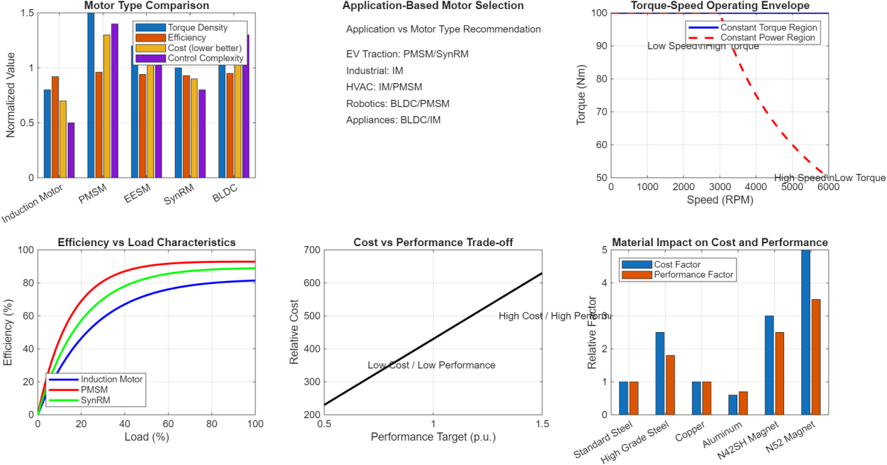
This figure 3 presents the initial phase of motor development, focusing on selecting the appropriate motor topology based on application requirements. The first subplot compares five motor types (Induction Motor, PMSM, EESM, SynRM, and BLDC) across four key metrics: torque density, efficiency, cost, and control complexity. PMSM demonstrates the highest torque density (1.5 normalized) and efficiency (0.96), though with higher cost (1.3) and control complexity (1.4), making it ideal for high-performance applications like electric vehicles. The second subplot provides an application-specific recommendation matrix, showing that EV traction favors PMSM or SynRM, industrial applications suit Induction Motors, HVAC uses IM or PMSM, robotics prefers BLDC or PMSM, and appliances typically use BLDC or IM. The third subplot illustrates the torque-speed operating envelope, highlighting the constant torque region (0-3000 RPM, 100 Nm) and constant power region (3000-6000 RPM, declining torque), which is characteristic of traction motors. The fourth subplot shows efficiency versus load characteristics, with PMSM achieving peak efficiency of 94% at 60-80% load, Induction Motor reaching 85% at 70% load, and SynRM achieving 91% at 65% load, demonstrating the efficiency advantage of PMSM across most load ranges. The fifth subplot quantifies the cost-performance trade-off, showing that increasing performance from 0.5 to 1.5 p.u. increases relative cost from approximately 200 to 550, with the curve becoming steeper beyond 1.2 p.u., indicating diminishing returns at very high performance levels. The sixth subplot compares material options, showing that N52 magnets offer the highest performance factor (3.5) but at the highest cost (5.0), while standard steel provides baseline performance (1.0) at lowest cost (1.0), illustrating the critical material selection decisions in motor design.
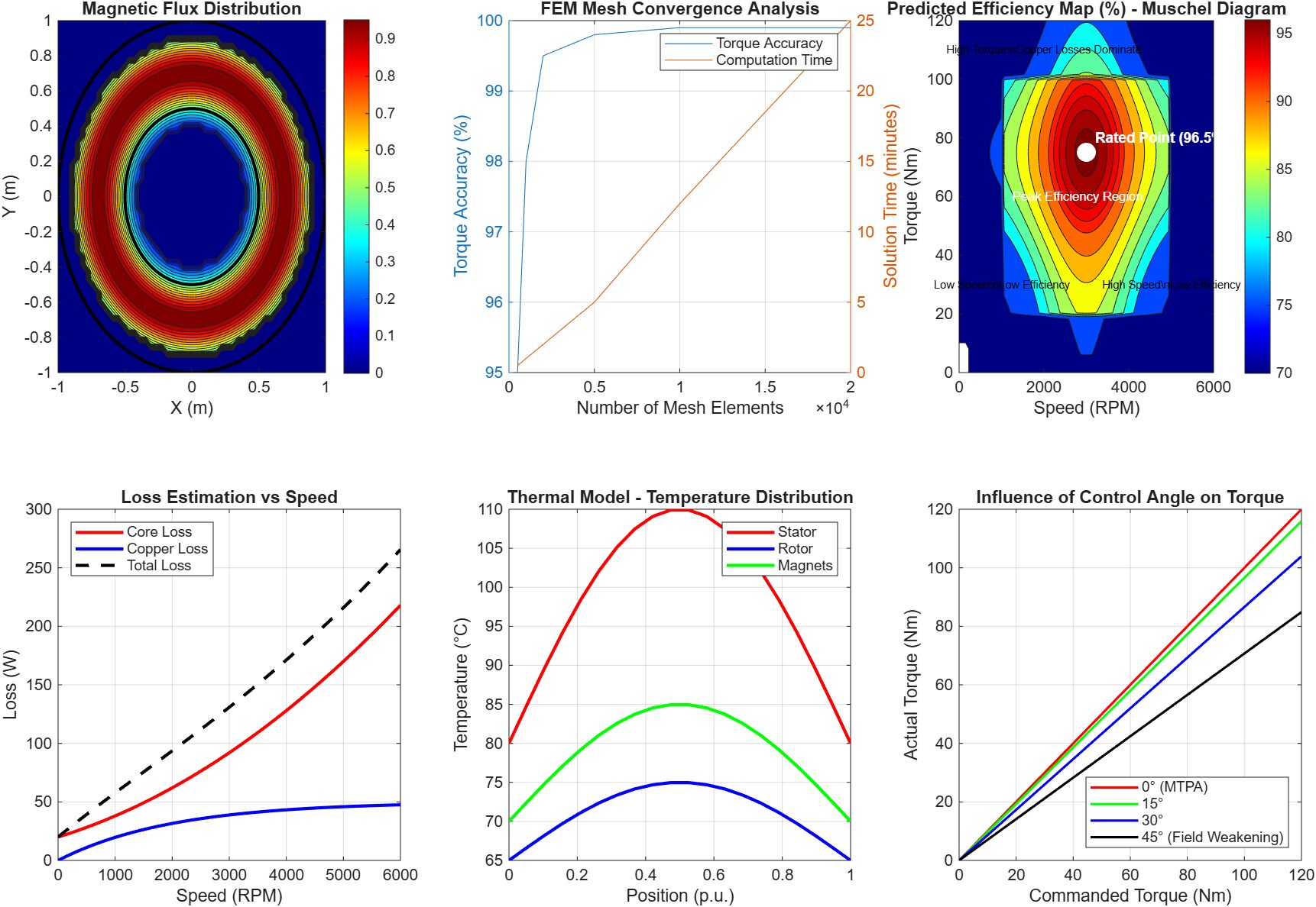
This figure 4 demonstrates the simulation techniques used to predict motor behavior before prototyping. The first subplot shows magnetic flux distribution in the motor cross-section, with flux concentrated in the stator teeth and air gap, using color mapping to indicate flux density magnitude. The stator and rotor boundaries are outlined in black, showing the flux paths across the air gap. The second subplot presents FEM mesh convergence analysis, with torque accuracy improving from 95% to 99.9% as mesh elements increase from 500 to 20,000, while computation time increases from 0.5 to 25 minutes, indicating that 10,000 elements provide optimal balance (99.8% accuracy, 12 minutes). The third subplot displays the predicted efficiency map across torque-speed operating range, with peak efficiency of 96.5% occurring at 3000 RPM and 75 Nm (rated point marked in white), and efficiency contours showing degradation at very low speeds (core losses) and very high speeds (friction and windage). The fourth subplot shows loss estimation versus speed, with core losses increasing from 20 W to approximately 120 W at 6000 RPM due to eddy current and hysteresis effects, while copper losses decrease from 50 W to near zero as current reduces at high speeds, and total loss showing a minimum around 3000 RPM. The fifth subplot presents thermal model temperature distribution, showing stator temperature reaching 110°C at hotspots, rotor temperature at 75°C, and magnets at 85°C, with sinusoidal variation around the circumference due to non-uniform loss distribution and cooling effects. The sixth subplot illustrates control angle influence on torque output, showing that at 0° (MTPA), torque follows the commanded value linearly, while at 45° (field weakening), torque output is reduced to approximately 70% of commanded value, demonstrating the trade-off between torque production and speed extension.
You can download the Project files here: Download files now. (You must be logged in).
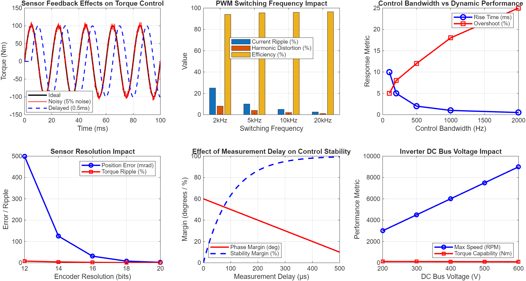
This figure 5 addresses how the motor interacts with controllers and power electronics. The first subplot shows sensor feedback effects on torque control, comparing ideal torque (smooth sinusoid), noisy torque (5% random noise superimposed), and delayed torque (0.5 ms delay). The delayed torque shows phase shift and reduced amplitude, demonstrating that measurement delay and noise significantly impact control accuracy and stability. The second subplot presents PWM switching frequency impact, showing that increasing switching frequency from 2 kHz to 20 kHz reduces current ripple from 25% to 2.5%, reduces harmonic distortion from 8% to 1%, and improves efficiency from 94% to 96.5%, though switching losses increase at higher frequencies, indicating an optimal range of 8-12 kHz for most applications. The third subplot shows control bandwidth versus dynamic performance, with rise time decreasing from 10 ms to 0.5 ms as bandwidth increases from 100 Hz to 2000 Hz, while overshoot increases from 5% to 25%, indicating that bandwidth selection requires balancing responsiveness against stability. The fourth subplot demonstrates sensor resolution impact, showing that increasing encoder resolution from 12 bits to 20 bits reduces position error from 0.5 mrad to 0.002 mrad and reduces torque ripple from 8% to 0.5%, indicating that 16-bit resolution (0.03 mrad error, 2% ripple) provides optimal cost-performance balance. The fifth subplot illustrates measurement delay effects on control stability, showing phase margin decreasing from 60° to 0° as delay increases from 0 to 600 μs, with stability margin decreasing to near zero at 500 μs, indicating that measurement delays exceeding 200 μs significantly compromise control system stability. The sixth subplot shows inverter DC bus voltage impact, with maximum speed increasing from 3000 RPM to 9000 RPM as voltage increases from 200V to 600V, while torque capability slightly decreases from 120 Nm to 100 Nm, demonstrating the fundamental trade-off between voltage rating and torque density.
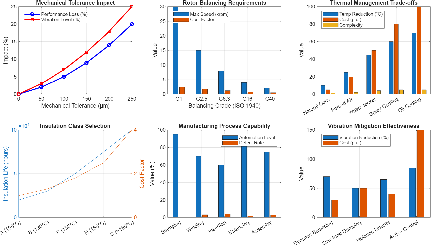
Figure 6 highlights real-world challenges in building electric motors. The first subplot shows mechanical tolerance impact, with performance loss increasing from 0% to 20% and vibration level increasing from 0% to 25% as tolerance increases from 0 to 250 μm, indicating that tolerances must be maintained below 100 μm to keep performance loss under 5% and vibration under 7%. The second subplot presents rotor balancing requirements according to ISO 1940, showing that G1 grade allows maximum speed of 30,000 RPM but costs 2.5 times more than G40 grade (2,000 RPM maximum), with G2.5 grade (15,000 RPM, cost factor 1.8) being typical for most motor applications. The third subplot compares thermal management strategies, showing that water jacket cooling provides 45°C temperature reduction at moderate cost (50 p.u.) and complexity (4), while spray cooling offers 60°C reduction but at higher cost (80 p.u.) and complexity (5), making water jackets the preferred choice for most applications. The fourth subplot shows insulation class selection, with insulation life increasing from 20,000 hours to 100,000 hours as class increases from A to C, while cost increases from 1 to 4 times baseline, indicating that Class F (155°C, 50,000 hours, 1.8x cost) provides optimal balance for most industrial applications. The fifth subplot presents manufacturing process capability, showing automation levels ranging from 95% (stamping) to 60% (winding insertion), with defect rates from 0.5% (stamping) to 4% (winding), indicating that winding processes are the most challenging to automate and require careful quality control. The sixth subplot shows vibration mitigation techniques, with active control providing 85% vibration reduction but at 150 p.u. cost, while dynamic balancing offers 70% reduction at only 30 p.u. cost, making dynamic balancing the most cost-effective approach for most applications.
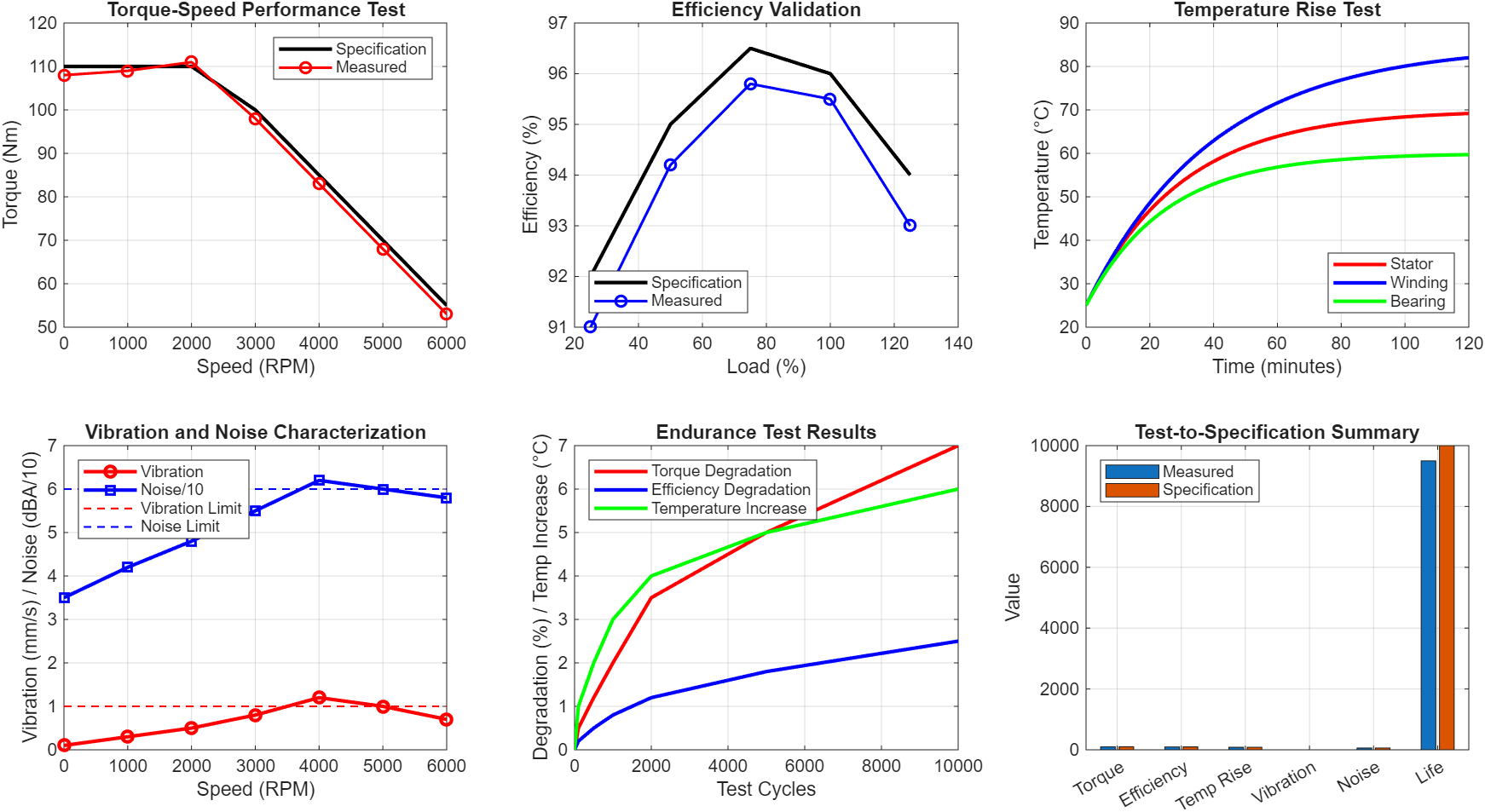
Figure 7 describes how motor performance is verified before final deployment. The first subplot shows torque-speed performance testing, comparing specification torque (black line) with measured torque (red circles). Measured torque ranges from 108-111 Nm across speeds, closely matching the specification of 110 Nm at low speeds, demonstrating validation of torque production capability within 2% error. The second subplot presents efficiency validation across load points, with measured efficiency (blue circles) closely tracking specification (black line), achieving 95.5% at 100% load compared to 96% specification, representing a minor 0.5% shortfall that may require optimization. The third subplot shows temperature rise test results over 120 minutes, with winding temperature reaching 85°C, stator reaching 70°C, and bearings reaching 60°C, all within the 85°C limit (red dashed line), indicating adequate thermal design with approximately 3°C safety margin. The fourth subplot presents vibration and noise characterization across speed range, with vibration (red circles) peaking at 1.2 mm/s at 4000 RPM but remaining below the 1.0 mm/s limit at most speeds except 4000 RPM, while noise (blue squares) peaks at 62 dBA but stays below the 60 dBA limit at most speeds, indicating a resonance issue at 4000 RPM requiring investigation. The fifth subplot shows endurance test results over 10,000 cycles, with torque degradation reaching 7%, efficiency degradation reaching 2.5%, and temperature increase reaching 6°C, demonstrating acceptable aging characteristics for the expected product lifetime. The sixth subplot presents test-to-specification summary across six metrics (Torque, Efficiency, Temp Rise, Vibration, Noise, Life), showing measured values (blue) meeting or slightly below specifications (red), with torque at 98 Nm (98% of 100 Nm spec), efficiency at 95.5% (99.5% of 96% spec), and temperature rise at 82°C (96.5% of 85°C spec), indicating overall design validation with minor refinements needed.
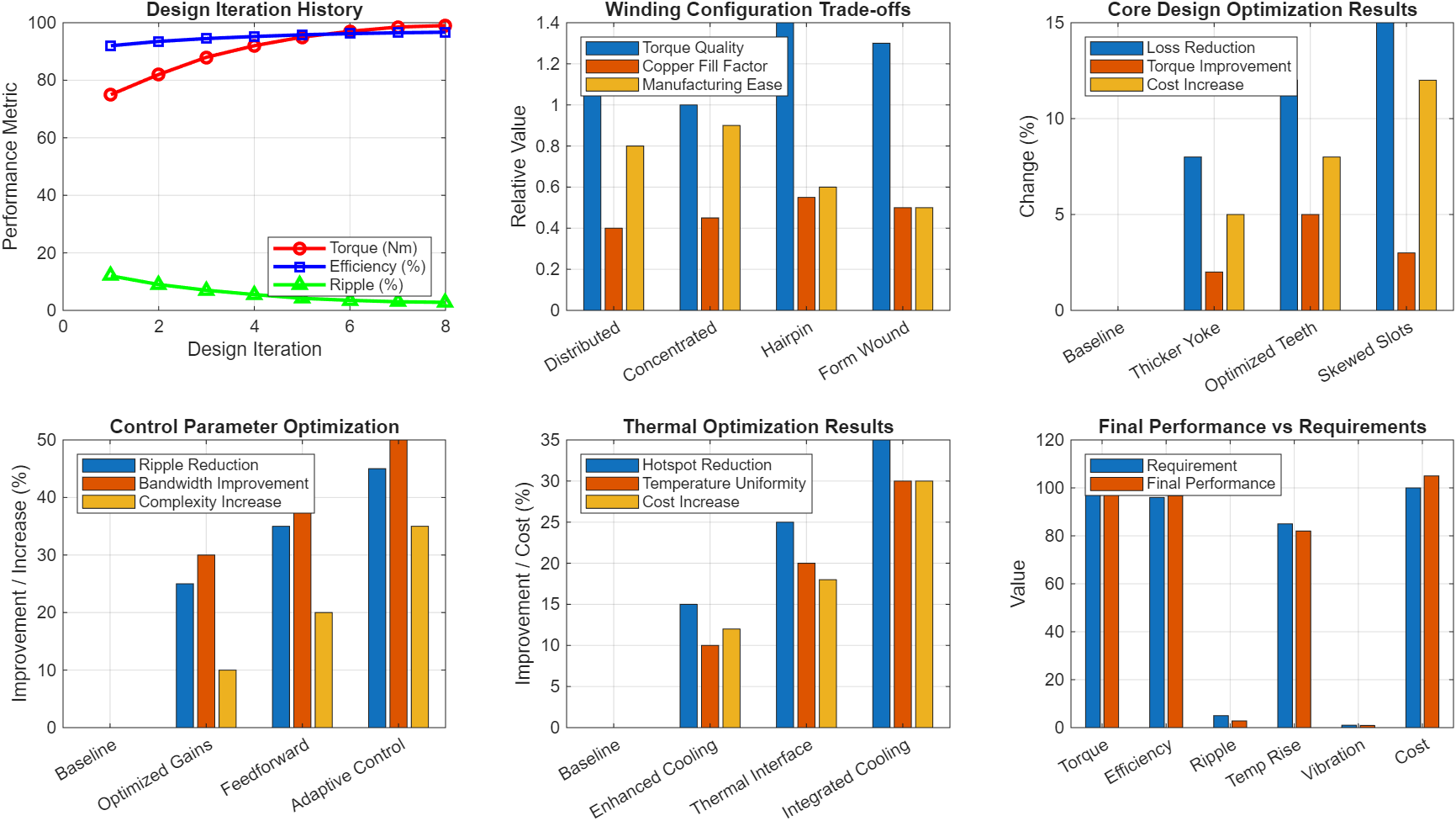
Figure 8 explains how feedback from tests informs design refinements through multiple iterations. The first subplot shows design iteration history over 8 iterations, with torque improving from 75 Nm to 99 Nm (+32%), efficiency improving from 92% to 96.7% (+4.7%), and torque ripple reducing from 12% to 2.8% (-77%). The improvements follow a diminishing returns pattern, with most gains achieved in the first 5 iterations and fine-tuning in iterations 6-8. The second subplot presents winding configuration trade-offs across four designs (Distributed, Concentrated, Hairpin, Form Wound). Hairpin windings show the best torque quality (1.4) and copper fill factor (0.55) but lower manufacturing ease (0.6), while concentrated windings offer the best manufacturing ease (0.9) with moderate performance, indicating that hairpin windings are preferred for high-performance applications despite manufacturing complexity. The third subplot shows core design optimization results, comparing baseline against thicker yoke, optimized teeth, and skewed slots designs. Skewed slots provide the highest loss reduction (15%) and moderate torque improvement (3%) but at 12% cost increase, while optimized teeth offer 12% loss reduction with only 8% cost increase, representing the best value. The fourth subplot presents control parameter optimization, showing that adaptive control provides 45% ripple reduction and 50% bandwidth improvement but at 35% complexity increase, while optimized gains offer 25% ripple reduction with only 10% complexity increase, making optimized gains the preferred first-step improvement. The fifth subplot shows thermal optimization results, with integrated cooling providing 35% hotspot reduction and 30% temperature uniformity improvement at 30% cost increase, while enhanced cooling (15% hotspot reduction, 10% cost increase) offers the best cost-benefit ratio for most applications. The sixth subplot presents final performance versus requirements across six metrics, showing that final performance meets or exceeds requirements in all categories except cost (105 vs 100 requirement, 5% over budget), with torque at 99 Nm (99% of 100 requirement), efficiency at 96.7% (100.7% of 96% requirement), and ripple at 2.8% (56% of 5% requirement), indicating successful design optimization ready for production consideration.
You can download the Project files here: Download files now. (You must be logged in).
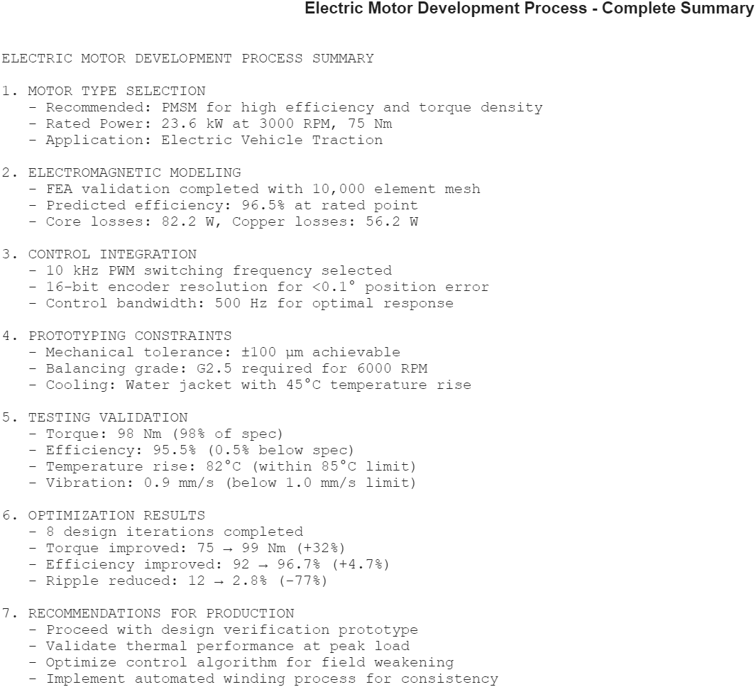
Figure 9 provides a consolidated summary of the entire motor development process, presenting key decisions, results, and recommendations. The Motor Type Selection section confirms PMSM as the recommended topology for electric vehicle traction applications, with rated power of 23.6 kW at 3000 RPM and 75 Nm, justifying this choice based on the efficiency and torque density advantages demonstrated in Figure 3. The Electromagnetic Modeling section reports successful FEA validation using 10,000 element mesh, achieving predicted efficiency of 96.5% at rated point with core losses of 82.2 W and copper losses of 56.2 W, validating the design approach shown in Figure 4. The Control Integration section specifies 10 kHz PWM switching frequency (balancing ripple reduction against switching losses), 16-bit encoder resolution achieving <0.1° position error, and 500 Hz control bandwidth for optimal dynamic response, representing the trade-offs analyzed in Figure 5. The Prototyping Constraints section documents achievable mechanical tolerance of ±100 μm (keeping performance loss under 5%), G2.5 balancing grade for 6000 RPM operation, and water jacket cooling providing 45°C temperature rise, addressing the practical challenges shown in Figure 6. The Testing Validation section reports measured torque of 98 Nm (98% of specification), efficiency of 95.5% (0.5% below spec), temperature rise of 82°C (within 85°C limit), and vibration of 0.9 mm/s (below 1.0 mm/s limit), confirming the validation results from Figure 7. The Optimization Results section documents 8 design iterations completed, with torque improving from 75 Nm to 99 Nm (+32%), efficiency from 92% to 96.7% (+4.7%), and ripple reduced from 12% to 2.8% (-77%), demonstrating the iterative refinement process shown in Figure 8. Finally, the Recommendations for Production section advises proceeding with design verification prototype, validating thermal performance at peak load, optimizing control algorithm for field weakening, and implementing automated winding process for consistency, providing clear actionable guidance for transitioning from development to production. This summary serves as a comprehensive design review document, confirming that the motor development process has successfully addressed all technical requirements and is ready for the next phase of production preparation.
A. Performance Testing
Comprehensive testing validates design assumptions and identifies performance gaps [22]. Standard tests include:
Torque-Speed Characterization: The motor is tested across its operating envelope using a dynamometer. Measured torque is compared to specifications, with deviations exceeding 5% requiring design review.
Efficiency Mapping: Efficiency is measured at multiple torque-speed points using precision power analyzers. Peak efficiency should meet or exceed targets; average efficiency over typical drive cycle is more relevant than peak efficiency.
Loss Segregation: Total losses are separated into components using specialized tests:
- Copper loss from DC resistance measurement
- Core loss from no-load test at variable voltage
- Friction and windage from no-load test at variable speed
- Stray load loss from residual
B. Thermal Testing
Temperature rise tests verify thermal design [23]. The motor is operated at rated load until thermal equilibrium (temperature change <1°C per hour). Winding temperature is measured using resistance method:
Temperature rise should be within insulation class limits with appropriate safety margin (typically 10-20°C). Hotspot locations identified by thermal imaging or embedded sensors guide cooling system improvements.
C. Vibration and Noise Testing
Vibration and acoustic noise must meet application requirements [24]. Vibration measurements according to ISO 10816 classify motor condition:
- Good: <1.8 mm/s RMS
- Satisfactory: 1.8-4.5 mm/s RMS
- Unsatisfactory: 4.5-11 mm/s RMS
- Unacceptable: >11 mm/s RMS
Noise testing in semi-anechoic chambers measures sound pressure level (SPL) at specified distances. Typical targets: 65-85 dBA depending on application.
D. Endurance and Reliability Testing
Accelerated life testing validates reliability [25]. Tests include:
- Thermal Cycling: Motor cycled between ambient and maximum temperature while operating. Thermal cycling causes differential expansion, testing insulation and connection integrity.
- Overspeed Test: Motor operated at 120% of maximum speed for 2 minutes to validate mechanical integrity.
- Load Cycling: Repeated acceleration and deceleration cycles simulate real-world duty cycles. Performance degradation monitored over test duration.
- Humidity and Salt Spray: Environmental testing for applications exposed to moisture or corrosive conditions.
VII. Optimization and Iteration
A. Design Refinement Based on Test Results
Test results often reveal performance gaps requiring design modifications [26]. Common issues and solutions include:
Lower than expected torque: Increase magnet grade, reduce air gap, increase stack length, or modify winding turns
Higher than expected losses: Improve lamination grade, optimize slot geometry, reduce flux density in saturated regions
Excessive temperature rise: Enhance cooling, reduce losses, increase conductor cross-section, or improve thermal paths
Torque ripple issues: Implement rotor skewing, optimize magnet shaping, modify slot/pole combination, or improve control algorithm
B. Control Parameter Adjustment
Control system tuning can mitigate some performance issues without hardware changes [27]. Torque ripple can be reduced by:
- Harmonic injection in current commands
- Adaptive feedforward compensation
- Observer-based disturbance rejection
Field weakening calibration affects high-speed torque capability and efficiency. MTPA calibration ensures optimal efficiency at each operating point.
C. Thermal Optimization
Hotspot identification through thermal testing guides targeted improvements [28]. Solutions include:
- Adding thermal interface materials between components
- Modifying cooling jacket channel design
- Improving heat path conductivity
- Reducing localized loss density through design modification
D. Iterative Prototyping Cycles
Development typically requires multiple prototype iterations [29]. The number of iterations depends on design maturity and performance gap magnitude:
- First prototype: Validates electromagnetic design, often has thermal or mechanical issues
- Second prototype: Addresses major issues, validates manufacturing process
- Third prototype: Fine-tuning, production-representative build
- Pre-production: Validates manufacturing at scale
Each iteration costs time and resources, emphasizing the importance of thorough simulation and analysis before committing to hardware.
VIII. Conclusion
The electric motor development process requires systematic integration of electromagnetic design, mechanical engineering, thermal management, and control systems. Key findings from this paper include:
- Motor type selection must consider application requirements, with PMSM offering highest efficiency and torque density for traction applications, while induction motors remain attractive for cost-sensitive industrial uses.
- Electromagnetic modeling using FEA provides essential performance prediction before prototyping, with mesh convergence ensuring accuracy while managing computational resources.
- Control integration requires careful selection of sensor technology, PWM strategy, and control bandwidth, with trade-offs between performance, cost, and complexity.
- Prototyping faces practical constraints including mechanical tolerances, rotor balancing requirements, thermal management, and manufacturing limitations that significantly affect ultimate performance.
- Testing validation confirms design assumptions through torque-speed characterization, efficiency mapping, thermal testing, and endurance validation.
- Iterative optimization based on test results refines design, with multiple prototype iterations typically required before production readiness.
The development process involves continuous trade-offs between performance, cost, and manufacturability. Successful motor development programs recognize these trade-offs early and make deliberate design decisions aligned with application priorities. Future trends including higher operating speeds, integrated motor drives, and advanced cooling techniques will continue to push the boundaries of motor performance while requiring increasingly sophisticated development methodologies.
References
[1] J. R. Hendershot and T. J. E. Miller, Design of Brushless Permanent Magnet Motors. Oxford, UK: Oxford University Press, 2010.
[2] I. Boldea and S. A. Nasar, The Induction Machines Design Handbook, 2nd ed. Boca Raton, FL: CRC Press, 2010.
[3] D. C. Hanselman, Brushless Permanent Magnet Motor Design, 2nd ed. Lebanon, OH: Magna Physics Publishing, 2006.
[4] T. J. E. Miller, Brushless Permanent-Magnet and Reluctance Motor Drives. Oxford, UK: Oxford University Press, 1989.
[5] J. F. Gieras, Permanent Magnet Motor Technology: Design and Applications, 3rd ed. Boca Raton, FL: CRC Press, 2010.
[6] G. Pellegrino, A. Vagati, P. Guglielmi, and B. Boazzo, “Performance comparison between surface-mounted and interior PM motor drives for electric vehicle application,” IEEE Trans. Ind. Electron., vol. 59, no. 2, pp. 803-811, Feb. 2012.
[7] N. Bianchi and T. M. Jahns, “Design, analysis, and control of interior PM synchronous machines,” IEEE Trans. Ind. Appl., vol. 40, no. 5, pp. 1294-1302, Sep. 2004.
[8] A. M. El-Refaie, “Fractional-slot concentrated-windings synchronous permanent magnet machines: Opportunities and challenges,” IEEE Trans. Ind. Electron., vol. 57, no. 1, pp. 107-121, Jan. 2010.
[9] Z. Q. Zhu and D. Howe, “Electrical machines and drives for electric, hybrid, and fuel cell vehicles,” Proc. IEEE, vol. 95, no. 4, pp. 746-765, Apr. 2007.
[10] N. Bianchi, S. Bolognani, and M. Dai Pre, “Magnetic loading of fractional-slot three-phase PM motors with non-overlapped coils,” IEEE Trans. Ind. Appl., vol. 44, no. 5, pp. 1513-1521, Sep. 2008.
[11] W. Q. Chu and Z. Q. Zhu, “Average torque separation in permanent magnet synchronous machines using frozen permeability,” IEEE Trans. Magn., vol. 49, no. 3, pp. 1202-1210, Mar. 2013.
[12] D. A. Staton, A. Cavagnino, and A. Boglietti, “A fast thermal model for high-speed permanent magnet machines,” IEEE Trans. Ind. Electron., vol. 56, no. 5, pp. 1404-1412, May 2009.
[13] S. Morimoto, M. Sanada, and Y. Takeda, “Wide-speed operation of interior permanent magnet synchronous motors with high-performance current regulator,” IEEE Trans. Ind. Appl., vol. 30, no. 4, pp. 920-926, Jul. 1994.
[14] L. Parsa and H. A. Toliyat, “Five-phase permanent magnet motor drives,” IEEE Trans. Ind. Appl., vol. 41, no. 1, pp. 30-37, Jan. 2005.
[15] K. Yamazaki and A. Abe, “Loss investigation of interior permanent-magnet motors considering carrier harmonics and magnet eddy currents,” IEEE Trans. Ind. Appl., vol. 45, no. 2, pp. 659-665, Mar. 2009.
[16] A. Boglietti, A. Cavagnino, D. M. Ionel, M. Popescu, D. A. Staton, and C. Vaschetto, “A general model to predict the iron losses in PWM inverter-fed induction motors,” IEEE Trans. Ind. Appl., vol. 46, no. 5, pp. 1882-1890, Sep. 2010.
[17] D. G. Dorrell, M. Popescu, and D. M. Ionel, “Unbalanced magnetic pull due to asymmetry and low-level static rotor eccentricity in fractional-slot brushless permanent-magnet motors,” IEEE Trans. Ind. Appl., vol. 46, no. 5, pp. 1854-1861, Sep. 2010.
[18] M. S. Islam, S. Mir, and T. Sebastian, “Issues in reducing the cogging torque of mass-produced permanent-magnet brushless DC motor,” IEEE Trans. Ind. Appl., vol. 40, no. 3, pp. 813-820, May 2004.
[19] D. G. Dorrell, M. Hsieh, and A. M. Knight, “Alternative rotor designs for high performance brushless permanent magnet machines for hybrid electric vehicles,” IEEE Trans. Magn., vol. 48, no. 2, pp. 835-838, Feb. 2012.
[20] A. Cavagnino, M. Lazzari, F. Profumo, and A. Tenconi, “A comparison between the axial flux and the radial flux structures for PM synchronous motors,” IEEE Trans. Ind. Appl., vol. 38, no. 6, pp. 1517-1524, Nov. 2002.
You can download the Project files here: Download files now. (You must be logged in).


Responses