

PMSM Motor Design Tool
PMSM motor design tool with winding layout synthesis, back-EMF, torque, losses, and animated rotating field stator diagram.

PMSM Motor Design & Winding Synthesis
Permanent Magnet Synchronous Machines (PMSM) are widely used in EV traction, robotics, machine tools, and aerospace drives due to high torque density, high efficiency, and dynamic performance.
#### Key Design Principles
- Winding Layout & Winding Factor:
Using the star of slot EMFs, the fundamental winding factor is synthesized:
- Air-Gap Flux Density:
With surface permanent magnets of remanence and thickness :
- Flux per Pole & Flux Linkage:
- Back-EMF & Electromagnetic Torque:
How it is calculated
Calculation and visualisation
- A three-phase winding layout and its working winding factor are obtained from the slot-EMF-star winding library.
- The analytical air-gap amplitude uses a uniform effective gap, surface-magnet remanence, and a sinusoidal pole-arc coefficient. Pole flux, phase linkage, open-circuit RMS back-EMF and ideal torque follow from that amplitude.
- The existing calculation named
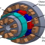
solve_pmsm_femis not finite-element analysis. It constructs a prescribed first- and third-harmonic flux-density waveform, applies a heuristic slot-permeance factor and solves a 60-point periodic smoothing system. Its peak and the resulting torque ratio are estimates, not validated FEM predictions. The existing output and plot labels containing “FEM” refer to this legacy approximation only. - The new full-width rotating cross-section is a visual aid: colour represents normalized synthetic intensity and dark contours are level sets of an invented angular/radial pattern, not magnetic flux lines. Slot and rotor outlines illustrate the geometry. Press ▶ on electrical angle to animate. Neither the colours nor the contours represent a magnetic solution or flux density in tesla.
Assumptions
- Surface-mounted permanent magnets, a three-phase winding, sinusoidal operation and ; iron saturation, leakage, magnet temperature and armature reaction are not solved.
- The new coloured field pattern is deliberately schematic; its spatial decay, ripple and colour scale are selected for appearance, not derived from Maxwell's equations. The stator slots shown there are schematic, not to-scale conductor geometry.
- The existing circumferential smoothing approximation is not FEM and has no validated accuracy for slotting, flux-density peaks or torque corrections.
- Copper geometry, winding resistance and core-loss estimates elsewhere in the tool are approximate sizing assumptions.
- The separate hairpin cross-section and optional magenta/cyan flux paths are schematic illustrations, not computed field lines or quantitative maps.
Where it applies
Valid for 3-phase surface permanent magnet machines with concentrated (FSCW) or distributed stator windings under sinusoidal current excitation.
References
- J. R. Hendershot and T. J. E. Miller, 'Design of Brushless Permanent-Magnet Motors', Magna Physics, 1994.
- N. Bianchi and S. Bolognani, 'Design techniques for reducing the cogging torque in surface-mounted PM motors', IEEE Trans. Ind. Appl., 2002.
- Z. Q. Zhu and D. Howe, 'Instantaneous magnetic field distribution in brushless permanent magnet machines', IEEE Trans. Magn., 1993.
Inputs
| Input | Symbol | Unit | Default |
|---|---|---|---|
| Stator slots (Q) Total number of stator slots. | Q | 48 | |
| Pole pairs (p) Number of rotor magnetic pole pairs (2p poles). E.g. Q=48, p=4 gives an 8-pole motor. | p | 4 | |
| Winding type Stator winding topology. | w_type | Double layer (overlapping) | |
| Coil pitch (y slots) Coil span in slot count for double-layer windings (y=6 full pitch, y=5 chorded 5/6). | y | 6 | |
| Stator bore diameter Inner bore diameter of the stator at the airgap. | D_si | mm | 120 |
| Active stack length Axial length of the stator core stack. | L_stk | mm | 110 |
| Air-gap clearance Mechanical radial clearance between stator bore and rotor surface. | g | mm | 1 |
| Stator slot width (bs) Width of the parallel-sided stator slot. | b_s | mm | 3.8 |
| Magnet thickness Radial thickness of surface permanent magnets. | h_m | mm | 3.5 |
| Magnet remanence (Br) Remanent magnetic flux density of magnets (e.g. 1.25 T for NdFeB). | B_r | T | 1.25 |
| Pole embrace (alpha_p) Ratio of magnet pole arc to pole pitch. | alpha_p | 0.8 | |
| Hairpin layers per slot (Ns) Number of hairpin conductors radially stacked in each slot (typically 6, 8, or 10). | N_s | 8 | |
| Rated phase current RMS phase current supplied by the inverter. | I_rms | A | 200 |
| Rated speed Rated mechanical rotational speed. | n_rpm | rpm | 3000 |
| Electrical angle (wt) Electrical angle of phase currents. Press ▶ to animate turning field! | wt | deg | 0 |
| Show rotating magnetic B field Show schematic rotating flux paths and radial flux direction (outward at N, inward at S). This is not a solved FEM field map. | show_B | true | |
| Show schematic flux lines Display illustrative closed flux loops from rotor north poles, through the air gap and stator yoke, to adjacent south poles, returning through the rotor. These are not field-solver streamlines or a flux-density map. | show_flux_lines | false | |
| Temperature unit Choose whether temperatures are specified in Celsius (�C) or Kelvin (K). | T_scale | Celsius (�C) | |
| Stator winding temperature Operating temperature of the stator hairpin copper winding (typically 65 �C to 150 �C for automotive EV). | T_winding | 80 | |
| Rotor magnet temperature Operating temperature of the rotor permanent magnets (typically 40 �C to 120 �C for NdFeB). | T_magnet | 60 | |
| Parallel paths (a) Number of parallel winding branches per phase (a=1 for series, a=2 for two parallel paths). | a_paths | 2 | |
| Inverter DC-link voltage DC supply voltage of the traction inverter (e.g. 800V). | V_dc | V | 800 |
Results
With the default inputs above, the calc gives:
| Result | Value |
|---|---|
| Electromagnetic Torque | 192.68 N·m |
| Mechanical Power | 60,533.4 W |
| Phase Back-EMF (RMS) | 100.9 V |
| Fundamental Winding Factor | 0.9659 |
| Torque Constant (RMS) | 0.963 N·m/A |
| Electrical Frequency | 200 Hz |
| Overall Motor Efficiency | 95.3 % |
| Peak Air-gap Flux Density | 1.11 T |
| FEM Corrected Torque | 154.88 N·m |
| FEM Slotted Flux Density | 0.89 T |
| Torque slotting reduction (FEM) | -19.617 % |
| Stator Tooth Width | 4.054 mm |
| Volumetric Power Density | 17.872 kW/L |
| Volumetric Torque Density | 56.889 N·m/L |
| Specific Power (Active) | 2.352 kW/kg |
| Specific Torque (Active) | 7.485 N·m/kg |
| Effective Remanence (at T_mag) | 1.195 T |
| Stator Phase Resistance | 0.01675 Ω |
| DC Copper Losses | 2,010.1 W |
| AC Copper Losses | 285.88 W |
| Total Copper Losses | 2,295.98 W |
| Stator Iron Losses | 178.3 W |
| Rotor Iron Losses | 1.66 W |
| Magnet Eddy Losses | 0.01 W |
| Total Iron & Magnet Losses | 180 W |
| Friction & Windage Losses | 489.3 W |
| Total Motor Losses | 2,965.2 W |
| Inverter Voltage Utilization | 30.9 % |
| Max Inverter Phase Voltage | 326.6 V |
Checked against sources
Each case below was calculated by this calc and agrees with the value from its source (within the tolerance where one is shown).
12-slot 10-pole concentrated winding factor
Source: Fractional-slot concentrated winding theory: for Q=12, p=5, coil pitch y=1, fundamental winding factor kw = sin(pi/12) / (1 * sin(pi/12)) * ... = 0.965926 (Bianchi & Bolognani, IEEE Trans. IA 2006).
Inputs: Stator slots (Q) = 12; Pole pairs (p) = 5; Winding type = Concentrated (alternate teeth); the others as above.
| Result | Source | This calc |
|---|---|---|
| Fundamental Winding Factor | 0.9659 ± 0.001 | 0.9659 |
Related Resources
Related articles

Related courses

Induction motor simulation using RMXPRT tool of ANSYS MAXWELL
1
Original price was: 50 €.12 €Current price is: 12 €.

IEC Electrical Schematics and Industrial Control Panels
5
Original price was: 42 €.21 €Current price is: 21 €.

Basic Electrical Controls & Diagram Reading
7
Original price was: 32 €.18 €Current price is: 18 €.









Responses