

Modeling Lithium-Ion Battery Chargers with only Resistor and RC packed using PLECS

Author: Waqas Javaid
Abstract
Lithium-ion batteries have become the preferred energy storage technology for electric vehicles, renewable energy storage systems, portable electronics, and industrial applications due to their high energy density, long cycle life, and low maintenance requirements. Accurate battery modeling is essential when designing charging systems, battery management systems, and power electronic converters. Simulation tools such as PLECS provide an efficient environment for evaluating charging strategies and analyzing the interaction between batteries and power converters before hardware implementation.
This article presents the modeling of lithium-ion battery chargers in PLECS® using electrical battery models suitable for system-level simulations. The discussion focuses on resistor-capacitor (RC) based battery models and resistor-only battery models. Furthermore, the implementation of battery pack models, converter modeling techniques, and Constant Current–Constant Voltage (CCCV) charging strategies are discussed. The advantages and limitations of each modeling approach are also highlighted.
1. Introduction
Lithium-ion batteries are widely used in modern electrical and electronic systems because of their excellent performance characteristics. During the design phase of battery-powered systems, simulation plays a vital role in evaluating charger performance, control algorithms, converter efficiency, and battery behavior under various operating conditions.
In many simplified simulations, batteries are represented as ideal voltage sources. Although this approach reduces model complexity, it fails to capture the nonlinear voltage-current characteristics of lithium-ion cells. In practical operation, battery terminal voltage changes continuously with the State of Charge (SOC), charging current, temperature, and internal electrochemical processes [1].
To achieve realistic simulation results, battery models must accurately represent the electrical behavior of the battery while maintaining acceptable simulation speed. Circuit-based battery models offer a suitable compromise between accuracy and computational efficiency. These models can be integrated directly with power electronic converters and control systems within the PLECS simulation environment.
2. Lithium-Ion Battery Modeling Approaches
Battery models can generally be classified into electrochemical models, mathematical models, and electrical circuit-based models [2].
Electrochemical models are highly detailed and are based on physical and chemical processes occurring inside the battery cell. These models provide excellent accuracy but require solving large sets of differential equations, resulting in long simulation times.
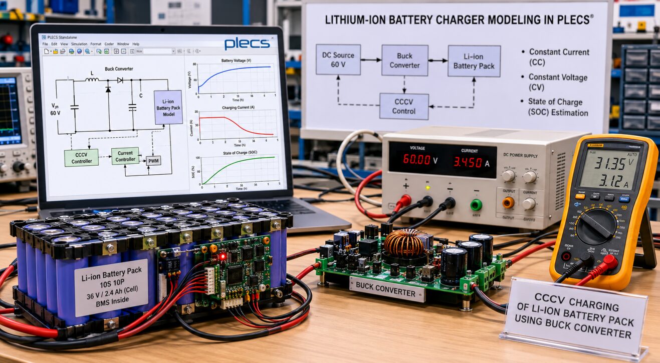
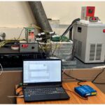
Figure 1: Experimental Setup and Simulation Framework for Lithium-Ion Battery Charger Modeling
Figure 1 illustrates a lithium-ion battery charging system comprising a 10S10P battery pack, a buck DC-DC converter, battery management and monitoring circuitry, and a DC power supply. The charging process follows a Constant Current–Constant Voltage (CCCV) profile, where battery voltage, charging current, and state of charge (SOC) are continuously monitored throughout the charging cycle. The setup represents the practical implementation of the battery charger model developed in PLECS and demonstrates the interaction between the power converter, battery pack, and control system.
Mathematical models use empirical relationships derived from experimental data. Such models are useful for estimating battery capacity and runtime but are often insufficient for analyzing the electrical interaction between batteries and power converters.
Electrical circuit-based models represent battery behavior using controlled voltage sources, resistors, and capacitors. These models provide realistic voltage-current characteristics while maintaining relatively fast simulation speed. Consequently, they are widely used in power electronics and battery charger development [2].
3. RC-Based Lithium-Ion Battery Model
The RC-based model represents the battery using an open-circuit voltage source together with internal resistive and capacitive elements. The model is capable of reproducing both steady-state and transient battery behavior.
The open-circuit voltage varies with battery SOC, while the internal resistances and capacitances represent electrochemical phenomena occurring within the cell. A series resistance models the instantaneous voltage drop observed when the load current changes. Additional RC networks reproduce both fast and slow transient responses associated with diffusion effects and electrode dynamics [3].
In practical battery operation, a sudden increase in load current produces an immediate voltage drop followed by gradual voltage recovery. The RC branches effectively capture this behavior and improve simulation accuracy.
The parameters of the RC model are typically obtained through laboratory testing and parameter identification procedures. Experimental data are collected across the entire SOC range, and mathematical functions are fitted to represent the variation of internal resistance, capacitance, and open-circuit voltage [4].
One significant advantage of the RC model is its ability to reproduce dynamic battery behavior accurately. However, parameter extraction can be time-consuming and often requires specialized equipment. Furthermore, the presence of multiple RC branches increases model complexity and may slow simulation performance, especially when large battery packs are considered.
4- Resistor-Only Lithium-Ion Battery Model
An alternative approach is the resistor-only battery model. This model eliminates the RC branches and instead focuses on reproducing the nonlinear voltage-SOC relationship using parameters commonly available in battery datasheets [5].
The resistor-only model provides a practical solution when detailed experimental battery data are unavailable. Since fewer parameters are required, implementation becomes significantly easier. The model is particularly suitable for system-level studies where overall charging behavior is more important than short-term transient dynamics.
The open-circuit voltage during discharge can be expressed as follows [6]:
Equation (1)

where:
- (V_OC) = Open-circuit battery voltage (V)
- (E_0) = Battery constant voltage (V)
- (K) = Polarization voltage constant (V)
- (Q) = Battery capacity (Ah)
- (i_t) = Extracted battery charge (Ah)
- (i^*) = Filtered battery current (A)
- (A) = Exponential zone voltage amplitude (V)
- (B) = Exponential zone time constant inverse (Ah(^-1))
This equation enables the model to reproduce the nonlinear discharge characteristics observed in lithium-ion batteries while maintaining a relatively simple structure.
Compared with the RC-based model, the resistor-only model offers significantly faster simulation speed. However, it does not accurately capture transient voltage responses associated with sudden current changes. Therefore, the selection of the model depends on the objectives of the simulation study.
You can download the Project files here: Download files now. (You must be logged in).
5. Battery Pack Modeling
Individual battery cells are typically connected in series and parallel combinations to achieve the required voltage and capacity ratings. Simulating hundreds of cells individually can result in excessive computational burden.
To improve simulation efficiency, an equivalent battery pack model can be developed by scaling the electrical characteristics of a single cell. The pack voltage is determined by the number of series-connected cells, while the overall capacity depends on the number of parallel branches [6].
This approach assumes that all cells operate under identical conditions and remain balanced throughout charging and discharging. Although cell-to-cell variations are neglected, the model provides sufficient accuracy for converter design and charging algorithm development.
6. Buck Converter Modeling in PLECS
Battery chargers commonly employ DC-DC converters to regulate charging current and voltage. In this work, a buck converter is used to step down the input voltage and charge the lithium-ion battery pack.
For long-duration charging simulations, an averaged converter model can be employed instead of a fully switched converter. Averaged models eliminate switching transitions and significantly reduce simulation time while preserving the overall dynamic behavior of the converter.
The inductor current dynamics of the buck converter can be represented by the following equation [7]:
Equation (2)
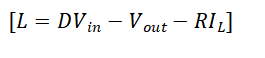
where:
- (L) = Inductance (H)
- (I_L) = Inductor current (A)
- (D) = Converter duty cycle
- (V_in) = Input voltage (V)
- (V_out) = Output voltage (V)
- (R) = Inductor series resistance (Ω)
This equation forms the basis of the averaged buck converter model implemented in PLECS. Controlled current sources and voltage measurements are used to reproduce converter behavior without explicitly modeling semiconductor switching actions.
The primary advantage of averaged models is their ability to simulate several hours of charging operation within seconds of computation time. However, switching losses, electromagnetic interference, and detailed converter waveforms cannot be analyzed using this approach.
7. Constant Current–Constant Voltage Charging Strategy
The Constant Current–Constant Voltage (CCCV) charging method is widely used for lithium-ion batteries because it provides a balance between charging speed, safety, and battery life.
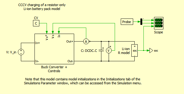
Figure 2: Constant Current–Constant Voltage (CCCV) charging of a resistor Li-ion battery circuit developed in PLECS
Figure 2 illustrates the Constant Current–Constant Voltage (CCCV) charging profile of a resistor-only lithium-ion battery model implemented in PLECS. During the initial stage of charging, the battery is charged at a constant current, resulting in a gradual increase in battery terminal voltage and state of charge (SOC). Once the battery voltage reaches the predefined charging limit, the controller transitions to constant-voltage mode, maintaining a fixed battery voltage while the charging current progressively decreases. This charging strategy ensures efficient energy transfer, prevents overcharging, and extends battery life. The resistor-only battery model accurately reproduces the overall voltage-current behavior of the lithium-ion battery while maintaining fast simulation speed, making it particularly suitable for system-level analysis and charger control development.
a) Model Parameter and code:
SimSetup = 1;
switch(SimSetup)
case 0
tsim = 3; % Simulated 1 second
SysConfig = 1; % Use fully switched buck converter with digital controls
case 1
tsim = 4.5*3600; % Simulated 4.5 hours
SysConfig = 2; % Use averaged model buck converter with continuous controls
end
V_in = 60; % DC input voltage
%% Battery Parameters
n_series = 10; % Number of series connected cells
n_parallel = 10; % Number of parallel branches
SOC_init = 0.5; % initial SOC
polarizingRshift = 0.10; % Shift polarizing R by 10%
cellNominalV = 2.9; % Voltage at end of nominal zone
cellFullChargeV = 3.3; % Voltage at full SOC
cellExponentialV = 3.05; % Voltage at end of exponential zone
cellRatedCapacity = 2.4; % Cell rated capacity
cellMaximumCapacity = 2.4; % Cell maximum capacity
cellNominalCapacity = 2.1; % Cell capacity at end of nominal zone
cellExponentialCapacity = 0.25; % Cell capacity at end of exponential zone
cellNominalDischargeI = 2.3; % Nominal discharge current for cell
cellInternalR = 6e-3; % Internal cell resistance
cellLPFTimeConstant = 30; % 30 second time constant for LPF for effect of current on voltage
%% Battery Pack controls
ConstI = 0.15*cellNominalDischargeI * n_parallel; % Target Constant charging current
ConstV = 0.95*cellFullChargeV * n_series; % Target Constant charging voltage
MAX_SOC = 0.99; % State of charge when battery charging is stopped
%% Buck Parameters:
DCDC.L = 1.5e-3; % [H] – Output inductances
DCDC.Lr= 0.01; % [Ohm] – Inductor resistance
DCDC.C = 800e-6; % [C] – Output capacitance
DCDC.fs = 15000; % [Hz] – Switching frequency
DCDC.Ts = 1/DCDC.fs; % [s] – Switching period
DCDC.Vamp = V_in; % [V] – Peak voltage amplitude
%% Current Controls
% Small time constants
CC.PWM = 0.5*DCDC.Ts; % [s] – PWM modulator small time constant
CC.Tcs = 1/(2*pi*(10*DCDC.fs)); % [s] – Current sensor small time constant
CC.f_samp = DCDC.fs; % [Hz] – Sampling frequency
CC.Tsp = 1/CC.f_samp; % [s] – Sampling small time constant
CC.Tpe = CC.PWM + CC.Tcs + CC.Tsp; % [s] – Equivalent small time constant
% Dominant time constants
CC.Tn=2*DCDC.L/(2*DCDC.Lr);
CC.Ti=2*CC.Tpe;
% Controller
CC.Kp=CC.Tn/CC.Ti;
CC.Ki=1/CC.Ti;
CC.Tp_current=2*sqrt(CC.Ti*CC.Tpe);
CC.K_aw=1/CC.Kp;
CC.upper=DCDC.Vamp;
CC.lower=0;
%% Voltage controller
VC.Tp_Vloop = CC.Tsp*2; %CC.Tp_current/2;
VC.Tsp=VC.Tp_Vloop;
VC.Ti_Vloop = 8/DCDC.C*VC.Tp_Vloop*VC.Tp_Vloop;
VC.Tn_Vloop = 4*VC.Tp_Vloop;
VC.Kp = VC.Tn_Vloop/VC.Ti_Vloop;
VC.Ki = 1/VC.Ti_Vloop;
VC.K_aw=1/VC.Kp;
VC.upper=ConstI;
VC.lower=0;
This PLECS model is configured to simulate the charging of a 10-series, 10-parallel lithium-ion battery pack using a buck converter operating under a Constant Current–Constant Voltage (CCCV) charging strategy. The parameter SimSetup selects either a detailed switched converter simulation (SimSetup = 0) for short-duration analysis or an averaged converter model (SimSetup = 1) for long-duration charging simulations of 4.5 hours with significantly reduced computation time. The battery pack is initialized at 50% state of charge (SOC) and is characterized using cell parameters such as full-charge voltage (3.3 V), nominal voltage (2.9 V), capacity (2.4 Ah), internal resistance (6 mΩ), and a low-pass filter time constant to capture current-dependent voltage behavior. The charging controller regulates the pack using a constant charging current of approximately 3.45 A until the battery reaches a voltage limit of 31.35 V, after which it transitions to constant-voltage operation and gradually reduces the charging current. Charging is terminated when the battery reaches 99% SOC. The buck converter is supplied from a 60 V DC source and consists of a 1.5 mH inductor, 800 µF output capacitor, and a switching frequency of 15 kHz. Separate PI controllers are designed for the current and voltage control loops, with gains calculated from the converter dynamics and sampling characteristics to ensure stable and accurate regulation of charging current and battery voltage throughout the charging process.
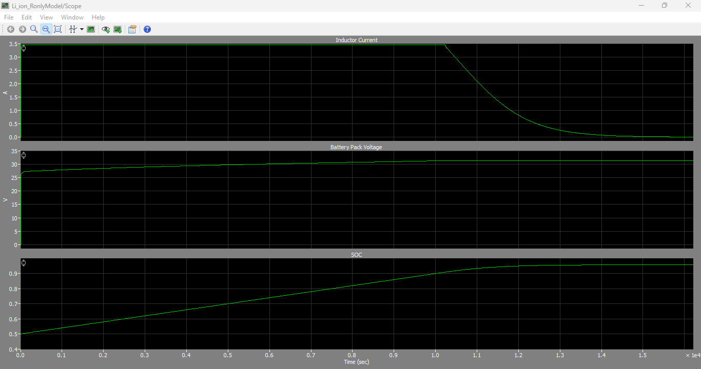
Figure 3: Inductor current, Battery pack voltage and SOC output graphs generated by Li-ion battery resistor only circuit in PLECS
You can download the Project files here: Download files now. (You must be logged in).
Figure 3 presents the simulated inductor current, battery pack voltage, and State of Charge (SOC) obtained from the resistor-only lithium-ion battery model developed in PLECS. The inductor current remains nearly constant during the constant-current charging phase, ensuring controlled energy transfer from the buck converter to the battery pack. Simultaneously, the battery pack voltage gradually increases as the battery stores energy and approaches its charging voltage limit. Once the constant-voltage stage is reached, the charging current begins to decrease while the battery voltage is maintained at the specified value. The SOC curve continuously increases throughout the charging process, indicating the accumulation of charge within the battery pack until the desired charge level is achieved. These results demonstrate the effectiveness of the CCCV charging algorithm and validate the ability of the resistor-only battery model to accurately represent the charging characteristics of a lithium-ion battery pack in system-level simulations.
During the initial stage of charging, the charger operates in constant-current mode. A fixed charging current is supplied to the battery while the terminal voltage gradually increases. Once the battery voltage reaches the specified charging limit, the charger transitions into constant-voltage mode. The battery voltage is maintained at a constant level while the charging current gradually decreases.
As the battery approaches full charge, the charging current becomes very small. At a predefined SOC or current threshold, the charging process is terminated to prevent overcharging and ensure battery safety.
The CCCV strategy can be implemented effectively in PLECS using either switched converter models or averaged converter models. The charging algorithm can be evaluated under different battery conditions and operating scenarios before hardware deployment.
8. Simulation Performance
Simulation speed is an important consideration when selecting battery and converter models. Fully switched converter models combined with detailed battery models provide high accuracy but often require long execution times.
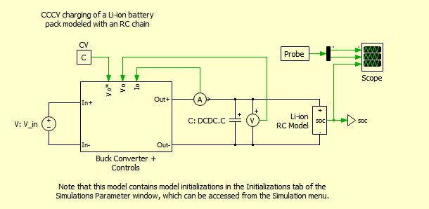
Figure 4: Constant Current–Constant Voltage (CCCV) charging of a Li-ion battery with RC circuit developed in PLECS
Figure 4 illustrates the CCCV charging behavior of a lithium-ion battery modeled using an RC-based equivalent circuit in PLECS. The RC network enables the model to capture both the steady-state and transient characteristics of the battery during charging. Initially, the battery is charged at a constant current, causing the terminal voltage and SOC to increase gradually. When the battery voltage reaches the specified charging limit, the controller switches to constant-voltage mode and the charging current decreases progressively until the desired SOC is achieved. The RC elements represent the electrochemical dynamics of the battery, allowing the model to reproduce the voltage transients and dynamic response that occur during charging more accurately than a resistor-only model.
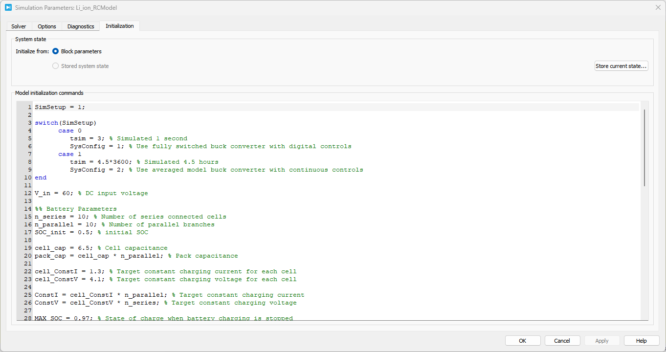
Figure 5: Block parameters defined for the Li-ion battery with RC model
You can download the Project files here: Download files now. (You must be logged in).
Figure 5 presents the parameter configuration of the RC-based lithium-ion battery model implemented in PLECS. The model consists of an open-circuit voltage source together with resistive and capacitive elements that represent the internal electrochemical behavior of the battery. Parameters such as battery capacity, internal resistance, RC branch resistances, RC branch capacitances, initial SOC, and voltage characteristics are defined within the model. These parameters are selected to emulate the dynamic charging and discharging performance of the battery and allow the simulation to accurately reproduce both transient and steady-state battery responses under different operating conditions.
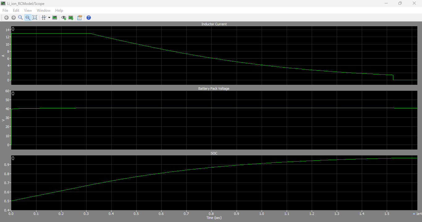
Figure 6: Inductor output current, Battery pack voltage and SOC output graphs generated by Li-ion battery with RC circuit in PLECS
Figure 6 shows the simulated inductor current, battery pack voltage, and State of Charge (SOC) obtained from the RC-based lithium-ion battery model during the charging process. The inductor current remains regulated during the constant-current charging stage and gradually decreases once the charger enters the constant-voltage region. The battery pack voltage increases steadily until reaching the prescribed charging voltage, after which it is maintained at a nearly constant level. Meanwhile, the SOC continuously rises as energy is stored within the battery pack. Due to the inclusion of RC networks, the model captures the dynamic voltage behavior and transient effects associated with internal battery processes, providing a more realistic representation of lithium-ion battery charging performance in comparison with simplified resistor-only models.
The RC-based battery model introduces additional dynamic states due to the RC networks, resulting in increased computational effort. In contrast, the resistor-only model requires fewer calculations and generally executes faster.
When averaged converter models are combined with continuous control systems, charging processes spanning several hours can be simulated within a fraction of a second. Such simulations are particularly useful for battery charger development, SOC estimation studies, and control algorithm verification.
9. Conclusion
Lithium-ion battery modeling is a critical aspect of charger design and power electronic system development. PLECS provides a flexible environment for implementing both detailed and simplified battery models depending on simulation requirements.
The RC-based battery model offers improved accuracy by capturing transient battery behavior and internal electrochemical dynamics. However, it requires extensive parameter identification and increases simulation complexity.
The resistor-only battery model provides a practical alternative when detailed battery data are unavailable. Although transient effects are neglected, the model accurately reproduces the overall voltage-current characteristics required for system-level studies.
Combined with averaged converter models and CCCV charging control, these battery models enable efficient evaluation of lithium-ion charging systems while maintaining realistic simulation behavior. The selection of the appropriate model ultimately depends on the balance between simulation accuracy and computational efficiency required by the application.
References
[1] L. Benini, G. Castelli, A. Macii, E. Macii, M. Poncino, and R. Scarsi, “Discrete-Time Battery Models for System-Level Low-Power Design,” IEEE Transactions on Very Large Scale Integration Systems, 2001.
[2] C. Min and G. Rincon-Mora, “Accurate Electrical Battery Model Capable of Predicting Runtime and I-V Performance,” IEEE Transactions on Energy Conversion, vol. 21, no. 2, pp. 504–511, 2006.
[3] H. Zhang and M.-Y. Chow, “Comprehensive Dynamic Battery Modeling for PHEV Applications,” IEEE Power and Energy Society General Meeting, 2010.
[4] L. Lam, P. Bauer, and E. Kelder, “A Practical Circuit-Based Model for Li-Ion Battery Cells in Electric Vehicle Applications,” IEEE INTELEC, 2011.
[5] O. Tremblay, L.-A. Dessaint, and A.-I. Dekkiche, “A Generic Battery Model for the Dynamic Simulation of Hybrid Electric Vehicles,” Vehicle Power and Propulsion Conference, 2007.
[6] O. Tremblay and L.-A. Dessaint, “Experimental Validation of a Battery Dynamic Model for EV Applications,” World Electric Vehicle Journal, 2009.
[7] Munadir Ahmed, “Modeling Lithium-Ion Battery Chargers in PLECS®,” Plexim Application Example, Version 02-16.
You can download the Project files here: Download files now. (You must be logged in).







Responses