

Real-Time Simulation and Implementation of a Grid-Connected Modular Multilevel Converter Using PLECS RT Box with Multi-Tasking Architecture
Author: Waqas Javaid
Abstract
This research presents the modeling, real-time implementation, and simulation analysis of a grid-connected Modular Multilevel Converter (MMC) using the PLECS RT Box platform developed by Plexim GmbH. The study focuses on the implementation of an open-loop controlled MMC system simulated under both single-tasking and multi-tasking execution modes. The converter is modeled using the PLECS environment and executed on the RT Box platform.
The MMC topology is composed of cascaded full-bridge submodules per arm, enabling scalable voltage synthesis and improved harmonic performance. The real-time simulation architecture is divided into multiple CPU-core tasks using Task Frame components, allowing computational distribution across processing units in RT Box 2 and RT Box 3 systems.
Two fundamental mathematical relationships governing the converter behavior are introduced and analyzed. The first equation describes the arm current dynamics, while the second defines the submodule capacitor voltage evolution. These equations are integrated into a real-time compatible discrete simulation framework. The results demonstrate that multi-tasking significantly reduces execution time and improves simulation fidelity by enabling smaller discretization steps.
Introduction
Power electronics systems have evolved significantly with the introduction of modular converter topologies, especially the Modular Multilevel Converter (MMC), which has become a key solution for medium and high-voltage applications such as HVDC transmission, renewable energy integration, and grid-tied inverter systems [1] [4].
Traditional two-level and three-level voltage source converters suffer from high switching losses and limited scalability. The MMC, however, provides superior voltage waveform quality, reduced harmonic distortion, and modular scalability due to its cascaded submodule structure. Each phase leg of the MMC consists of upper and lower arms, each containing multiple submodules with capacitors that contribute to voltage synthesis [3].
The increasing complexity of MMC systems necessitates advanced simulation tools capable of real-time execution. In this context, the PLECS environment combined with RT Box hardware provides a powerful solution for hardware-in-the-loop (HIL) and real-time validation. The simulation framework allows both offline and real-time execution with configurable task distribution across multiple CPU cores [5].
The present work focuses on a grid-connected MMC system implemented using PLECS and executed on RT Box. The study emphasizes multi-tasking execution to improve computational efficiency and reduce discretization time steps.
Modular Multilevel Converter Topology
The MMC consists of three-phase converter legs, where each phase contains an upper and lower arm. Each arm includes a series connection of identical submodules, typically full-bridge or half-bridge configurations. In this work, full-bridge submodules are used to provide enhanced control flexibility, including bipolar voltage output capability.
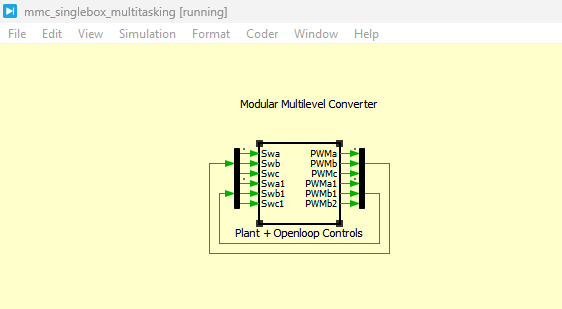
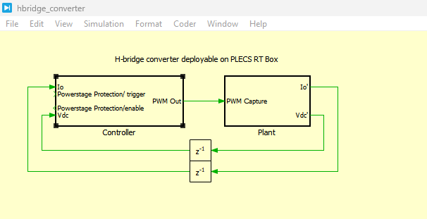
Figure 1: Top level schematic of MMC schematic model Plant + Openloop Controls in PLECS Simulation
Figure 1 illustrates the top-level schematic of the Modular Multilevel Converter (MMC) simulation model developed in the PLECS environment, consisting of the “Plant” subsystem and the “Open-loop Controls” block. The Plant subsystem represents the complete power stage of the MMC, including the three-phase converter structure, DC-link source, AC grid interface, and arm inductors. Each phase leg is constructed using upper and lower arms composed of cascaded full-bridge submodules, which collectively synthesize the required AC output voltage from the DC input. The physical behavior of the converter, including switching dynamics, energy storage in capacitors, and current flow through inductive elements, is captured within this Plant model to ensure realistic representation of the power electronic system.
The Open-loop Controls block is responsible for generating the gating signals required to operate the converter without feedback regulation. These signals are typically produced using predefined PWM modulation strategies and are routed to the corresponding switches of the MMC through digital signal interfaces. In this configuration, both the Plant and control systems operate within the same simulation framework, allowing synchronized execution of switching actions and electrical responses. The model is also structured to support real-time deployment on the RT Box platform, where the system can be executed in single-tasking or multi-tasking mode to evaluate computational performance and dynamic behavior under realistic operating conditions.
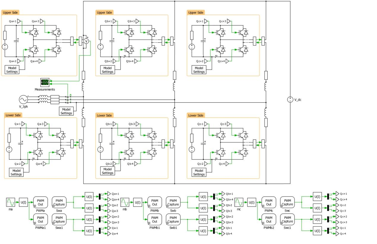
Figure 2: Schematic of the grid-connected MMC inverter developed in PLECS
You can download the Project files here: Download files now. (You must be logged in).
Figure 2 illustrates the detailed schematic of the grid-connected Modular Multilevel Converter (MMC) inverter developed in the PLECS simulation environment. The converter structure is composed of three-phase legs, where each phase consists of an upper and lower arm connected between the DC link and the AC grid. Each arm is built using a series connection of full-bridge submodules, each containing a DC-link capacitor and semiconductor switching devices. This modular structure allows the inverter to synthesize high-quality AC voltage waveforms by selectively inserting or bypassing submodules, thereby controlling the effective arm voltage. The DC side provides a constant voltage source, while the AC side is connected to the grid through arm inductors and line impedance, which help in limiting current ripple and improving dynamic stability.
In addition to the power circuit, the schematic also includes the PWM generation and signal routing mechanism used for switching control. The gating signals (Swa, Swb, Swc and their complementary signals) are generated through an open-loop modulation strategy and then applied to the corresponding submodules in each arm. Measurement blocks are integrated to capture key electrical variables such as capacitor voltages, arm currents, and grid-side currents, which are essential for performance evaluation. The model is configured for real-time execution using the PLECS environment on the RT Box platform, enabling both single-tasking and multi-tasking execution modes for computational efficiency and high-fidelity dynamic analysis.
Each submodule contains a DC-link capacitor, which acts as an energy storage element. The capacitor voltages collectively determine the arm voltage and ultimately the AC-side output voltage.
The total number of submodules per arm is configurable, and in this study, a default value of five submodules per arm is considered. The scalability of the system is achieved using implicit vectorization, where the number of submodules is defined through a parameter without modifying circuit wiring.
The MMC is connected between a DC source and an AC grid. The AC side includes grid impedance and inductance, which influence current dynamics and power transfer characteristics [6].
The converter operates under open-loop PWM control, where switching signals are generated externally and fed back into the system using digital I/O routing. This structure allows validation of converter dynamics without closed-loop regulation complexity.
Mathematical Modeling of the MMC System
The dynamic behavior of the MMC can be described using arm current equations and capacitor voltage evolution equations. In this work, two primary equations are considered to represent the system behavior.
3.1. Arm Current Dynamics
The arm current dynamics can be expressed as [1][2]:
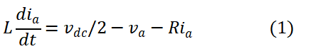
This equation represents the upper arm current dynamics of one phase.
Where:
- ia is the arm current of phase A
- Lis the equivalent arm inductance
- R is the equivalent arm resistance
- vdc is the total DC-link voltage
- vais the AC-side phase voltage contribution from the converter
The equation 1 describes how the arm current evolves based on the voltage difference between the DC bus and AC output, while accounting for inductive and resistive effects. The inductance LLL limits current ripple, while resistance RRR represents conduction and switching losses.
The term vdc/2 represents the voltage contribution of each arm in a split DC-link configuration. The subtraction of va reflects the modulation impact of switching states.
3.2. Submodule Capacitor Voltage Dynamics
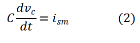
The capacitor voltage dynamics of each submodule are given by [3]:
Where:
- vc is the capacitor voltage of a submodule
- C is the submodule capacitance
- ism is the current flowing through the submodule
The equation 2 indicates that capacitor voltage variation is directly dependent on the current flowing through the submodule. Positive current charges the capacitor, increasing its voltage, while negative current discharges it.
In an MMC structure, maintaining balanced capacitor voltages across all submodules is critical for stable operation. Voltage imbalance may lead to unequal stress distribution and degraded converter performance.
You can download the Project files here: Download files now. (You must be logged in).
Real-Time Simulation Architecture
The system is implemented using the PLECS RT simulation environment integrated with RT Box hardware [7]. The RT Box platform enables deterministic execution of power electronics models with microsecond-level time steps.
The simulation can be executed in two modes:
4.1. Single-Tasking Mode
In single-tasking mode, the entire MMC model is executed on a single CPU core. This approach simplifies execution but increases computational load per cycle. The discretization step size is relatively larger, limiting simulation resolution. Single-tasking is primarily used for simpler real-time experiments or when hardware constraints exist, such as RT Box 1.
4.2. Multi-Tasking Mode
In multi-tasking mode, the MMC model is partitioned into multiple tasks distributed across CPU cores. Typically:
- Core 0: AC grid and interface dynamics
- Core 1: Upper arm submodules
- Core 2: Lower arm submodules
This partitioning significantly reduces execution time per task. Each core processes a smaller portion of the system, allowing a reduced global time step.
The Task Frame mechanism ensures that subsystem boundaries are properly defined, and coupling between tasks is achieved using controlled voltage and current sources.
A one-step delay element is introduced in feedback paths to prevent algebraic loops and ensure numerical stability in real-time execution.
PWM Generation and Open-Loop Control
The system operates under open-loop control, where PWM signals are externally generated and routed through digital I/O channels. The PWM signals are then captured and reinjected into the simulation environment.
This structure allows:
- Validation of switching behavior
- Verification of arm voltage synthesis
- Analysis of harmonic content
- Observation of real-time response without control feedback complexity
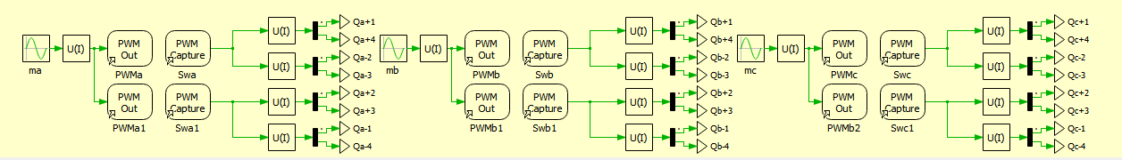
Figure 3: PWM generation strategy developed in PLECS simulation
Figure 3 illustrates the Pulse Width Modulation (PWM) generation strategy implemented in the PLECS simulation environment for controlling the switching behavior of the Modular Multilevel Converter (MMC). The PWM block is responsible for generating precise gate signals for each submodule in the upper and lower arms of the converter based on a predefined modulation reference. In this open-loop control configuration, the modulation signals are typically derived from sinusoidal reference waveforms compared against a high-frequency triangular carrier signal. The comparison process determines the switching states of the semiconductor devices, thereby controlling the insertion and bypassing of submodules to synthesize the desired output voltage waveform. This approach ensures that the converter produces a controlled AC voltage from the DC input while maintaining synchronization with the grid frequency.
In addition to signal generation, the PWM strategy includes signal routing and conditioning elements to ensure compatibility with the RT Box digital I/O interface. The generated PWM signals are distributed to different phases (Swa, Swb, Swc and their complementary signals), ensuring coordinated switching across all converter arms. Dead-time implementation and signal synchronization are also incorporated to avoid shoot-through conditions and ensure safe switching transitions. The PWM signals are then captured back into the simulation through feedback loop connections using digital capture blocks, allowing real-time validation of switching performance. Overall, this PWM strategy forms a critical part of the MMC control architecture, enabling stable and accurate modulation of the converter in both offline and real-time simulation modes using PLECS and RT Box.
The PWM strategy determines the switching state of each submodule, thereby controlling the insertion or bypassing of capacitors in the arm circuit. The modulation index plays a key role in defining output voltage magnitude and is directly related to converter performance.
Real-Time Execution and Performance Analysis
The use of multi-tasking significantly improves simulation performance by distributing computational load across multiple CPU cores [8]. According to system configuration, the execution time per step is reduced compared to single-tasking mode.
The reduction in computational load enables:
- Smaller discretization steps
- Improved waveform accuracy
- Higher switching resolution
- Better harmonic representation
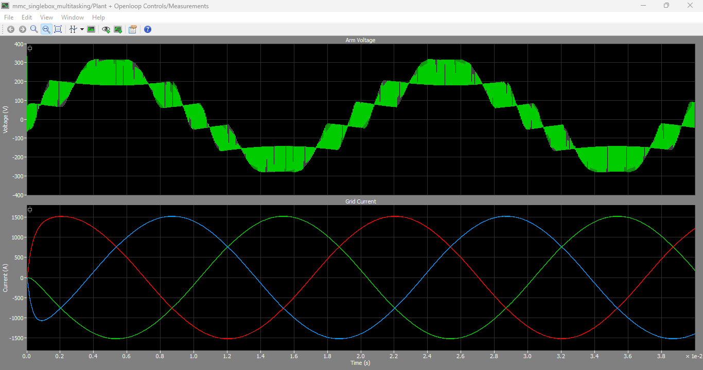
Figure 4: Real-time measurements obtained on the RT Box in multi-tasking mode including Arm voltage and Grid current output waveforms
You can download the Project files here: Download files now. (You must be logged in).
Figure 4 presents the real-time experimental results obtained from the PLECS RT Box during multi-tasking operation of the grid-connected Modular Multilevel Converter (MMC) system. The waveforms include the arm voltage and grid current responses, which are key indicators of converter performance and system stability. In multi-tasking mode, the computational load is distributed across multiple CPU cores, enabling reduced discretization time and improved temporal resolution of the simulation. As a result, the arm voltage waveform exhibits a well-defined stepped multilevel structure, reflecting the switching behavior of the MMC submodules. This staircase-like voltage profile confirms proper modulation and accurate execution of switching states under real-time constraints.
The grid current waveform shown in Figure 4 demonstrates smooth sinusoidal behavior, indicating effective energy transfer from the DC side to the AC grid with reduced harmonic distortion. The current response also reflects stable dynamic performance under open-loop control conditions, with minimal oscillations and good synchronization with the converter output voltage. The results validate the effectiveness of the multi-tasking implementation on the RT Box platform, where distributed processing enhances computational efficiency without compromising waveform accuracy. Overall, these real-time measurements confirm that the developed MMC model in PLECS is capable of achieving high-fidelity performance suitable for hardware-in-the-loop and advanced power electronics research applications.
In practical real-time operation, the RT Box system maintains synchronization between electrical variables and digital signals using external mode communication.
The measured arm voltages and grid currents demonstrate stable waveform behavior, confirming correct MMC operation under open-loop conditions.
Discussion
The results demonstrate that modular simulation of MMC systems using real-time platforms significantly enhances system analysis capabilities. The ability to distribute computation across multiple cores is essential for large-scale converter models, particularly when the number of submodules increases.
The main advantage of multi-tasking lies in its scalability. As the number of submodules increases, computational demand grows linearly, making single-core execution inefficient. Multi-core distribution resolves this limitation.
The use of controlled source coupling between subsystems ensures numerical stability while maintaining physical accuracy. However, introducing delays may slightly affect high-frequency dynamics, which must be considered during model design.
The open-loop control strategy simplifies system evaluation but does not address capacitor voltage balancing or closed-loop stability. Future improvements can include closed-loop control strategies such as nearest-level modulation or model predictive control.
Conclusion
This research presented a comprehensive real-time simulation study of a Modular Multilevel Converter implemented using PLECS and executed on RT Box hardware. The system was analyzed under both single-tasking and multi-tasking execution modes.
Two fundamental equations governing arm current and capacitor voltage dynamics were derived and explained in detail. The results confirm that multi-tasking execution significantly enhances computational efficiency and reduces simulation time while improving discretization resolution.
The proposed framework demonstrates strong potential for real-time validation of large-scale power electronic systems and provides a foundation for future development of advanced control strategies for MMC-based grid applications.
References
- Marquardt, R., & Lesnicar, A. (2003)“A New Modular Voltage Source Inverter Topology” IEEE Conference on Power Electronics Specialists Conference (PESC).
- Debnath, S., Qin, J., Bahrani, B., & Saeedifard, M. (2015)“Operation, Control, and Applications of the Modular Multilevel Converter: A Review” IEEE Transactions on Power Electronics, 30(1), 37–53 DOI: 10.1109/TPEL.2014.2309938
- Gowaid, I. A., et al. (2015)“Control of Modular Multilevel Converters for HVDC Applications” IEEE Transactions on Power Delivery
- Plexim GmbH, “PLECS User Manual and RT Box Documentation,” Zurich, Switzerland, 2023.
- Jacobson et al., “Modular Multilevel Converter for HVDC Applications,” IEEE Transactions on Power Electronics, 2010.
- RT Box Technical Documentation, Plexim GmbH, RT Box TSP 2.2.1, 2023.
- Hatziargyriou, “Power Electronics in Modern Power Systems,” IEEE Press, 2019.
- Kundur, P., “Power System Stability and Control,” McGraw-Hill, 1994.
You can download the Project files here: Download files now. (You must be logged in).


Responses