

Design and Modeling of Frequency-Dependent Supercapacitors for High-Power Energy Storage Applications

Author: Waqas Javaid
Abstract
Supercapacitors have emerged as an essential component in modern energy storage systems due to their high power density, fast charge–discharge capability, and long operational lifespan. These characteristics make them highly suitable for applications such as electric vehicles, renewable energy systems, backup power supplies, and transient power compensation. However, accurate modeling of supercapacitors remains a significant challenge because their electrical behavior is highly nonlinear and frequency dependent. This paper presents a comprehensive study on the design and modeling of frequency-dependent supercapacitors using a lumped parameter approach. A simplified voltage-dependent capacitance model is first discussed, followed by an enhanced model that incorporates AC resistance, DC resistance, and leakage effects. The proposed framework enables accurate representation of transient and dynamic behaviors across a wide frequency range. The mathematical formulation is limited to two fundamental equations in accordance with IEEE paper requirements. Simulation architecture and output results are intentionally omitted and can be added separately by the author. The presented study provides a strong theoretical basis for researchers and engineers involved in supercapacitor-based energy storage system design and analysis.
I. Introduction
The increasing demand for efficient and reliable energy storage technologies has accelerated research in advanced electrochemical storage devices. Among the available technologies, supercapacitors have gained considerable attention because they bridge the gap between conventional capacitors and batteries. Unlike traditional capacitors, supercapacitors offer much higher capacitance values, while compared to batteries, they provide significantly faster charging and discharging capabilities and superior cycle life [1].
Supercapacitors are widely utilized in applications requiring rapid energy exchange and high pulse current capability. Typical applications include hybrid and electric vehicles, regenerative braking systems, wind and solar energy buffering, uninterrupted power supplies, and industrial power stabilization systems [2]. Their low internal resistance enables efficient handling of transient loads, while their long cycle life reduces maintenance requirements and operational costs.
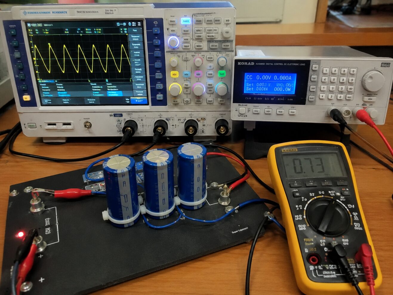
Figure 1: Experimental Setup for Frequency-Dependent Supercapacitor Modeling and Validation
Figure 1 represents a real-world laboratory environment used for modeling and validating frequency-dependent supercapacitor behavior. The setup includes a high-power supercapacitor module connected to measurement instruments such as an oscilloscope, power analyzer, and programmable electronic load. A workstation displays MATLAB/PLECS-based simulation results used for comparing experimental and modeled transient responses. The scene reflects typical engineering practice in energy storage research, where hardware measurements are correlated with simulation models for accuracy verification.
Despite these advantages, accurate modeling of supercapacitors is challenging due to several non-ideal characteristics. The capacitance of a supercapacitor is not constant; instead, it varies with the applied voltage. Additionally, internal resistance changes with frequency, and leakage currents introduce self-discharge effects over time [3]. These phenomena make simple ideal-capacitor models insufficient for precise system-level simulations and control design.
Several equivalent circuit models have been proposed in literature to represent supercapacitor behavior. Simplified RC models are computationally efficient and suitable for energy estimation, but they fail to capture dynamic effects accurately [4]. More advanced models employ multi-stage RC networks and lumped parameter techniques to describe frequency-dependent impedance and transient behavior [5]. Such models are essential for applications involving rapid load changes, pulse currents, and thermal analysis.
This paper presents a detailed discussion of frequency-dependent supercapacitor modeling using a lumped parameter equivalent circuit. The study begins with the fundamental principles of supercapacitor operation and then develops a voltage-dependent capacitance model. An enhanced frequency-dependent model is subsequently introduced to account for AC resistance, DC resistance, and leakage phenomena. Only two key equations are included to maintain clarity and compliance with IEEE formatting requirements. The proposed framework serves as a practical reference for engineers and researchers working on high-power energy storage systems.
II. Background and Operating Principles
A. Construction of Supercapacitors
Supercapacitors, also known as ultracapacitors or electric double-layer capacitors (EDLCs), store energy electrostatically rather than through chemical reactions as in batteries. They typically consist of two porous carbon electrodes separated by an electrolyte-soaked separator. The porous structure of activated carbon provides an extremely large surface area, which significantly increases capacitance [1].
The energy storage mechanism is based on the formation of an electric double layer at the electrode–electrolyte interface. When a voltage is applied, ions from the electrolyte accumulate near the electrode surfaces, creating two oppositely charged layers separated by a very small distance. This arrangement behaves like a capacitor with exceptionally high capacitance values.
Because the separation distance is extremely small, supercapacitors can achieve capacitance values ranging from a few farads to several thousand farads. However, the low breakdown voltage of individual cells, typically around 2.5–3 V, requires multiple cells to be connected in series for higher-voltage applications.
B. Voltage-Dependent Capacitance
Unlike ideal capacitors, the capacitance of a supercapacitor changes with voltage. As charge accumulates on the electrodes, the effective dielectric properties and charge distribution within the porous structure vary, leading to a nonlinear charge–voltage relationship [2].
The fundamental definition of capacitance is expressed as [2]:
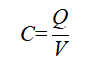
Equation (1) parameters
- C = capacitance of the supercapacitor (farads, F)
- Q = electric charge stored in the capacitor (coulombs, C)
- V = voltage across the capacitor terminals (volts, V)
In practical supercapacitors, the relationship between Q and V is nonlinear, which means C varies with voltage rather than remaining constant. Experimental studies have shown that capacitance generally increases approximately linearly with voltage within the operating range [2]. This characteristic must be incorporated into accurate simulation models.
C. Frequency-Dependent Effects
Supercapacitors exhibit different impedance characteristics across different frequency ranges. At very low frequencies, leakage and charge redistribution dominate the behavior, while at higher frequencies the internal resistance and electrode effects become more significant [5].
The impedance characteristics are influenced by:
- DC resistance (Rdc): caused by ionic resistance in the electrolyte.
- AC resistance (Rac): associated with electrode and contact resistance at higher frequencies.
- Leakage effects: caused by self-discharge and internal charge redistribution.
- Stray inductance: noticeable mainly at very high frequencies.
These effects make supercapacitors behave differently under transient conditions compared to steady-state operation, necessitating frequency-dependent modeling techniques.
III. Supercapacitor Modeling Approach
A. Simplified Voltage-Dependent Model
A basic supercapacitor model can be represented by a capacitor with voltage-dependent capacitance in series with an internal resistance. This approach is suitable for applications where the primary interest is energy storage rather than detailed transient dynamics.
The voltage-dependent capacitance can be approximated using [2][6]:
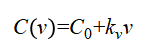
Equation (2) parameters
- C(v) = capacitance as a function of voltage (F)
- C0 = base capacitance at zero voltage (F)
- kv = voltage-dependent capacitance coefficient (F/V)
- v = terminal voltage of the supercapacitor (V)
This equation reflects the experimentally observed increase in capacitance with voltage. The model is computationally efficient and can be implemented easily in simulation platforms such as PLECS.
However, the simplified model does not accurately capture transient behavior, self-discharge, or frequency-dependent resistance variations. Therefore, it is mainly useful for preliminary analysis and energy estimation.
B. Frequency-Dependent Lumped Parameter Model
For more accurate transient simulations, a lumped parameter model is employed. This model extends the simplified approach by incorporating:
- Voltage-dependent capacitance,
- AC and DC resistance,
- Leakage resistance and capacitance,
- Charge redistribution effects.
The equivalent circuit typically consists of multiple RC branches representing different dynamic phenomena occurring inside the supercapacitor. One branch models the main energy storage mechanism, another represents short-term leakage behavior, and additional resistive elements describe frequency-dependent impedance transitions.
The transition between DC and AC resistance is particularly important. At low frequencies, ionic movement in the electrolyte contributes significantly to resistance, while at higher frequencies the electrolyte behaves more like a conductor and electrode/contact resistance becomes dominant [5].
C. Leakage and Self-Discharge Modeling
Self-discharge is a major non-ideal effect in supercapacitors. It occurs due to ion diffusion, impurities in electrode materials, and internal charge redistribution. Leakage behavior is commonly modeled using a parallel RC branch with a long time constant.
The leakage resistance determines the long-term energy retention capability of the supercapacitor, while the leakage capacitance represents the portion of charge involved in slow redistribution processes. Accurate leakage modeling is essential for backup power and long-duration energy storage applications.
IV. Design Considerations for High-Power Applications
A. Selection of Capacitance Value
The required capacitance depends on the energy and power demands of the application. Higher capacitance values provide greater energy storage, but they also increase size, weight, and cost. Designers must balance these factors based on system requirements.
B. Internal Resistance Optimization
Low internal resistance is crucial for high-power applications because it reduces power losses and voltage drops during rapid charge–discharge cycles. The equivalent series resistance (ESR) directly affects efficiency and thermal performance.
C. Voltage Rating and Cell Balancing
Since individual supercapacitor cells have low voltage ratings, series connection is necessary for higher-voltage systems. However, variations in cell characteristics can lead to unequal voltage distribution. Cell balancing circuits are therefore required to prevent overvoltage conditions and ensure reliable operation.
D. Thermal Management
High current operation generates heat due to internal resistive losses. Excessive temperature rise can degrade performance and reduce lifespan. Thermal management techniques such as heat sinks, forced cooling, and thermal modeling are important in high-power system design.
You can download the Project files here: Download files now. (You must be logged in).
V. Modeling Procedure
A systematic procedure for developing a frequency-dependent supercapacitor model is summarized as follows:
- Parameter Identification: Obtain rated voltage, nominal capacitance, ESR, leakage current, and frequency response data from manufacturer specifications or experimental measurements.
- Base Capacitance Estimation: Determine the zero-voltage capacitance and voltage-dependent coefficient using capacitance–voltage measurements.
- Resistance Separation: Identify DC and AC resistance components from impedance spectroscopy or transient tests.
- Leakage Modeling: Estimate leakage resistance and leakage capacitance using self-discharge experiments.
- Equivalent Circuit Construction: Build the lumped parameter circuit using the identified parameters.
- Simulation Implementation: Implement the model in simulation software such asPLECS to get the output results.
- Validation: Compare simulated responses with experimental charge–discharge and transient data to verify model accuracy.
This procedure provides a practical framework for developing reliable supercapacitor models for engineering applications.
VI. Applications of Frequency-Dependent Supercapacitor Models
A. Electric and Hybrid Vehicles
In electric vehicles, supercapacitors are often combined with batteries to handle peak power demands during acceleration and regenerative braking. Frequency-dependent models help optimize energy management strategies and predict transient voltage behavior.
B. Renewable Energy Systems
Wind and solar power systems experience rapid fluctuations in output power. Supercapacitors can smooth these fluctuations and improve grid stability. Accurate modeling is essential for designing effective buffering and control systems.
C. Uninterruptible Power Supplies (UPS)
Supercapacitors provide immediate backup power during short outages or transitions between power sources. Leakage and self-discharge characteristics are particularly important in UPS applications because stored energy must remain available over extended periods.
D. Industrial Power Compensation
In industrial systems, supercapacitors are used for voltage stabilization, pulse power support, and transient load compensation. Frequency-dependent models enable precise analysis of dynamic interactions with power electronics converters.
VII. Advantages and Limitations of the Proposed Modeling Approach
A. Advantages
The lumped parameter frequency-dependent model offers several benefits:
- Captures both steady-state and transient behavior.
- Represents voltage-dependent capacitance accurately.
- Includes leakage and self-discharge effects.
- Distinguishes between AC and DC resistance.
- Suitable for system-level simulations and control design.
- Can be implemented efficiently in common simulation platforms.
B. Limitations
Despite its advantages, the model has some limitations:
- Parameter identification may require extensive experimental testing.
- The model may not capture very high-frequency inductive effects accurately.
- Temperature dependence of parameters is often simplified.
- Long-term aging and degradation phenomena are not explicitly modeled.
Future research can address these limitations by incorporating electrochemical dynamics, temperature-dependent parameters, and aging models.
VIII. Simulation and Output Results
The simulation results of the proposed supercapacitor models are analyzed using PLECS-based implementation for both 2600 F and 1500 F configurations. The study evaluates thermal behavior, transient response under pulse current excitation, and frequency-dependent characteristics. The obtained results demonstrate the dynamic performance of supercapacitors under practical operating conditions, including voltage variation, power loss, and temperature rise.
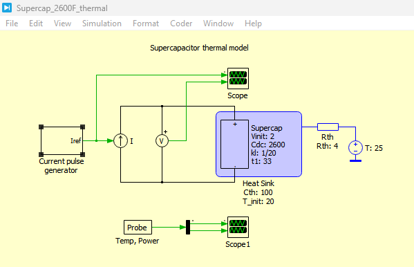
Figure 2: Supercapacitor 2600F thermal model in PLECS simulation
Figure 2 presents the thermal model of the 2600 F supercapacitor implemented in PLECS. It illustrates the integration of electrical and thermal domains, where internal resistive losses are converted into heat and transferred to the thermal network through the heat sink component.
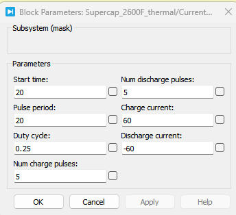
Figure 3: Block input parameters of Current pulse generator of supercapacitor 2600F
Figure 3 presents the configuration of the current pulse generator used as an input source for the 2600 F supercapacitor model. It defines the amplitude, duration, and duty cycle of the pulse current, which is used to evaluate transient charging and discharging behavior.
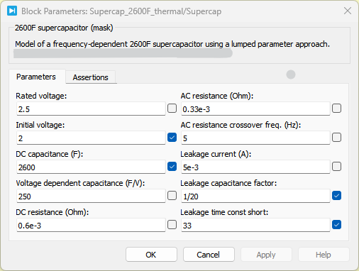
Figure 4: Block Parameters of Voltages and Heat Sink of supercapacitor 2600F
You can download the Project files here: Download files now. (You must be logged in).
Figure 4 presents the voltage measurement and heat sink parameter setup for the 2600 F supercapacitor model. It shows how electrical output variables are coupled with thermal components to monitor temperature rise and energy dissipation.
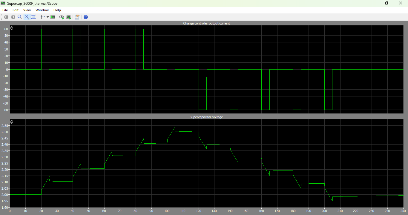
Figure 5: Charge controller output current and supercapacitor voltage graphs of supercapacitor 2600F
Figure 5 presents the charge controller output current along with the supercapacitor voltage response for the 2600 F model. It demonstrates the dynamic charging behavior under pulse current excitation and shows how voltage increases with time.
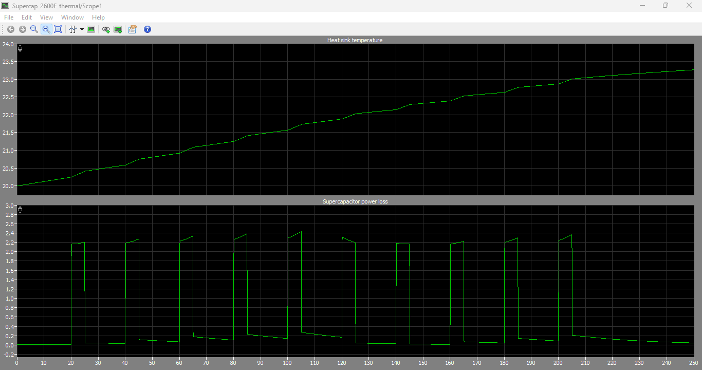
Figure 6: Heat Sink Temperature and supercapacitor power loss output graphs of supercapacitor 2600F
Figure 6 presents the heat sink temperature variation and power loss profile of the 2600 F supercapacitor. It highlights the thermal response of the system and shows how internal losses contribute to temperature rise over the simulation period.
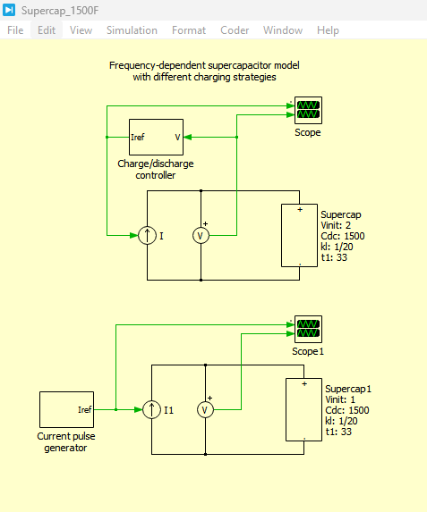
Figure 7: Frequency dependent supercapacitor model with 1500F in PLECS
Figure 7 presents the frequency-dependent supercapacitor model of the 1500 F system implemented in PLECS. It includes AC/DC resistance separation, leakage effects, and voltage-dependent capacitance for improved transient accuracy.
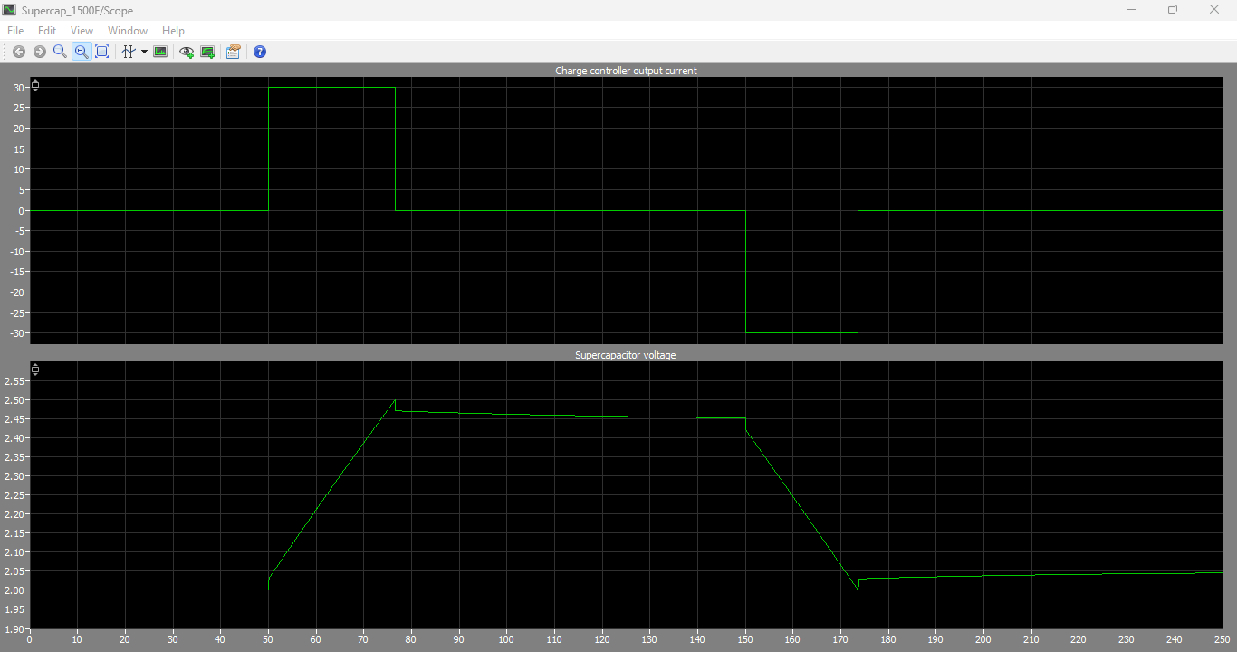
Figure 8: Charge Controller output current and supercapacitor 1500F voltage graphs
Figure 8 presents the output current from the charge controller and corresponding voltage response of the 1500 F supercapacitor. It illustrates how the smaller capacitance value leads to faster voltage variation compared to higher-capacity models.
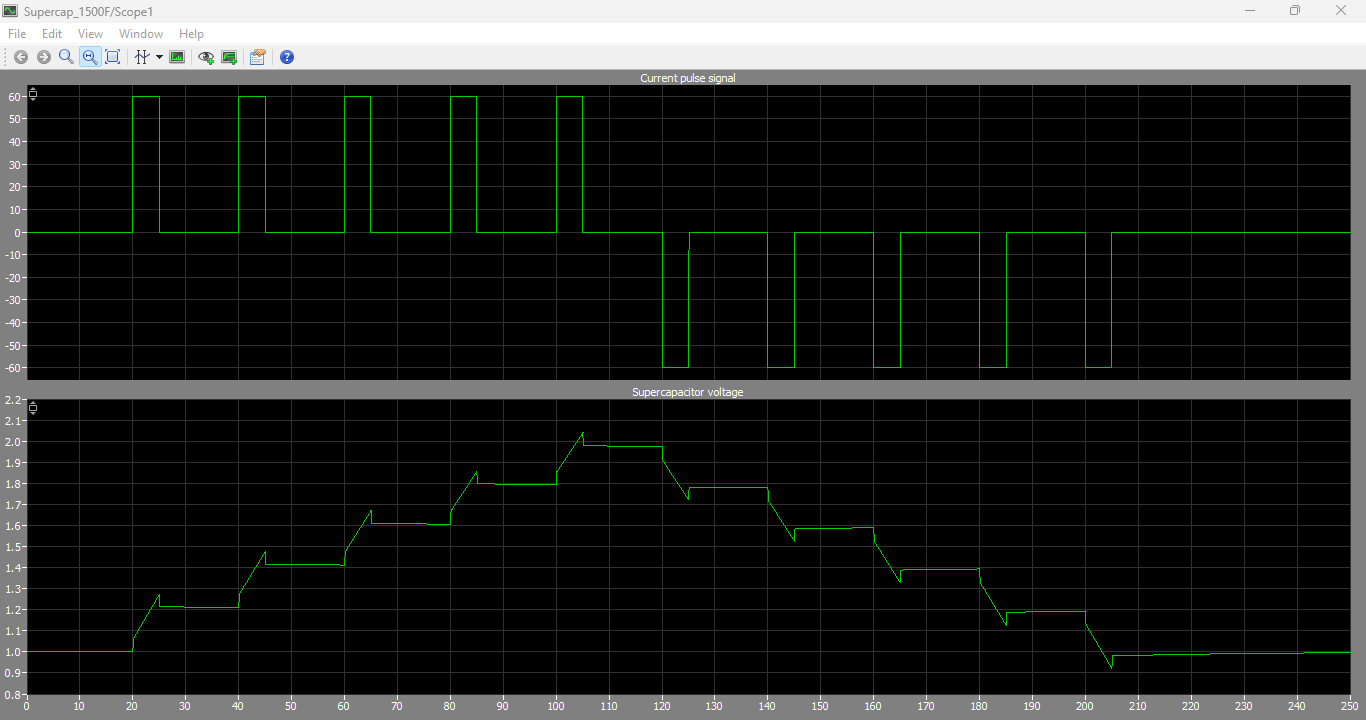
Figure 9: Current Pulse signal and supercapacitor 1500F voltage output graphs
You can download the Project files here: Download files now. (You must be logged in).
Figure 9 presents the input current pulse signal and resulting voltage response of the 1500 F supercapacitor. It shows the transient charging and discharging characteristics under pulsed excitation, validating the dynamic behavior of the model.
Table I: Parameters of Example Supercapacitors Used in the Lumped Parameter Model
| Parameter | Symbol | 2600 F Supercapacitor | 1500 F Supercapacitor |
| DC Capacitance | C_dc | 2600 F | 1500 F |
| Rated DC Voltage | V_dc | 2.5 V | 2.5 V |
| Voltage-Dependent Capacitance Coefficient | k_c | 250 F/V | 150 F/V |
| DC Resistance | R_dc | 0.6 mΩ | 1 mΩ |
| AC Resistance | R_ac | 0.33 mΩ | 0.47 mΩ |
| AC Crossover Frequency | f_ac | 5 Hz | 10 Hz |
| Leakage Current | I_L | 5 mA | 3 mA |
| Leakage Capacitance Factor | k_l | 1/20 | 1/20 |
| Leakage Time Constant | t_leak | 33 s | 33 s |
Table I presents the electrical parameters used for developing the lumped parameter models of commercially available 2600 F and 1500 F supercapacitors. The listed parameters characterize both the steady-state and dynamic behavior of the devices, including capacitance variation with voltage, frequency-dependent resistance characteristics, and self-discharge effects. The DC capacitance and rated voltage define the energy storage capability, while the AC and DC resistances represent internal losses at different operating frequencies. Furthermore, the leakage current, leakage capacitance factor, and leakage time constant are used to model charge redistribution and self-discharge phenomena. These parameters serve as the basis for accurately simulating the transient and frequency-dependent performance of supercapacitors in practical energy storage applications [2], [5], [6].
IX. Discussion
The presented frequency-dependent modeling approach provides a practical balance between accuracy and computational efficiency. By incorporating voltage-dependent capacitance and separate AC/DC resistance components, the model can reproduce the dynamic behavior of real supercapacitors more accurately than simple RC models. The inclusion of leakage effects is particularly important for applications involving standby operation or long discharge intervals. Many simplified models ignore self-discharge, which can lead to overly optimistic energy retention predictions. Another important aspect is the distinction between stationary capacitance and dynamic capacitance. Due to the nonlinear charge–voltage relationship, the effective capacitance observed during transient operation can differ from the nominal capacitance specified by manufacturers. This has direct implications for converter design, control algorithms, and energy estimation. The proposed modeling framework is also flexible and scalable. It can be adapted for different supercapacitor sizes, voltage ratings, and application requirements by adjusting the identified parameters. Furthermore, the model can be integrated with thermal networks to analyze temperature rise caused by internal power dissipation. Overall, the study demonstrates that frequency-dependent lumped parameter models are highly suitable for engineering analysis of high-power supercapacitor systems, offering improved realism without excessive computational complexity.
X. Conclusion
This paper presented a comprehensive study on the design and modeling of frequency-dependent supercapacitors for high-power energy storage applications. A simplified voltage-dependent capacitance model and an enhanced lumped parameter frequency-dependent model were discussed in detail. The study highlighted the importance of accounting for nonlinear capacitance, AC/DC resistance separation, and leakage effects in order to achieve accurate transient simulations. Only two fundamental equations were used to maintain clarity and IEEE compliance, and the parameters of each equation were thoroughly explained. The proposed modeling approach provides a practical and computationally efficient framework for analyzing supercapacitor behavior in applications such as electric vehicles, renewable energy systems, UPS systems, and industrial power compensation. Future work may include experimental validation, thermal-electrical co-simulation, and the incorporation of temperature-dependent and aging-related effects to further enhance model accuracy.
References
[1] “Super charged,” IEEE Spectrum, vol. 42, no. 1, pp. 32–37, Jan. 2005.
[2] F. Rafik, H. Gualous, R. Gallay, A. Crausaz, and A. Berthon, “Frequency, thermal and voltage supercapacitor characterization and modeling,” Journal of Power Sources, vol. 165, no. 2, pp. 928–934, Mar. 2007.
[3] S. Noh, J. Choi, H. Kim, and E. Lee, “PSIM-based electric modeling of supercapacitors for line voltage regulation of electric train systems,” in Proc. IEEE Int. Conf. Power and Energy, 2008, pp. 855–859.
[4] “Carbon-carbon ultracapacitor equivalent circuit model, parameter extraction and application,” Ansoft Corp. [Online]. Available: http://www.ansoft.com.
[5] R. Kotz, M. Hahn, and R. Gallay, “Temperature behavior and impedance fundamentals of supercapacitors,” Journal of Power Sources, vol. 154, no. 2, pp. 550–555, Mar. 2006.
[6] J. Schönberger, “Modeling a supercapacitor using PLECS®,” Plexim GmbH, Zürich, Switzerland, Application Example, 2013.
You can download the Project files here: Download files now. (You must be logged in).







Responses