

FOC and Vector Control in Electric Motor Systems: Mathematical Modeling, Real-Time Implementation, and Performance Validation

Author: Waqas Javaid
Abstract
The increasing demand for high-performance electric drive systems in industrial automation, electric vehicles, renewable energy conversion, and robotics has made advanced motor control techniques essential. Modern electric machines cannot achieve accurate speed regulation, high efficiency, and rapid dynamic response using conventional open-loop control approaches. Field-oriented control (FOC), also known as vector control, provides a systematic solution by transforming the coupled three-phase machine variables into a rotating reference frame where torque and flux components can be independently controlled. This paper presents a comprehensive analysis of FOC-based motor drive systems, including mathematical transformation principles, closed-loop current and speed control strategies, machine-specific implementation aspects, sensor-based and sensorless operation, field weakening techniques, real-time implementation challenges, and system-level validation. A complete PMSM vector control model is developed in MATLAB, including Clarke and Park transformations, proportional-integral current regulators, speed control loops, PWM inverter operation, and fault protection mechanisms. Simulation results demonstrate the ability of FOC to achieve accurate torque production, fast transient response, improved efficiency, and stable operation under variable loading conditions. The interaction between electromagnetic, thermal, mechanical, and safety aspects is also discussed to provide a complete perspective on modern electric drive control.
I. Introduction
Electric motors represent one of the most widely used energy conversion systems in modern electrical and industrial applications. From electric vehicles and robotics to industrial motion systems and renewable energy generators, the performance of the motor drive directly determines system efficiency, dynamic response, reliability, and operational safety. Unlike traditional motor operation where speed control was achieved through simple voltage or frequency adjustment, modern electric drive systems require precise control of torque, magnetic flux, and mechanical motion. Therefore, motors are no longer operated as independent electrical machines but as integrated electromechanical systems controlled through advanced algorithms.
The fundamental challenge in controlling AC machines is the inherent coupling between torque-producing and flux-producing components. In a conventional three-phase machine, stator currents simultaneously influence both magnetic field generation and torque production, making direct torque regulation difficult. Scalar control methods such as voltage-to-frequency (V/f) control modify the applied voltage magnitude and frequency while maintaining approximate flux conditions, but they cannot independently regulate torque and flux during dynamic operation [1]. As a result, scalar methods suffer from slower transient response, reduced efficiency, and limited performance under rapidly changing loads.
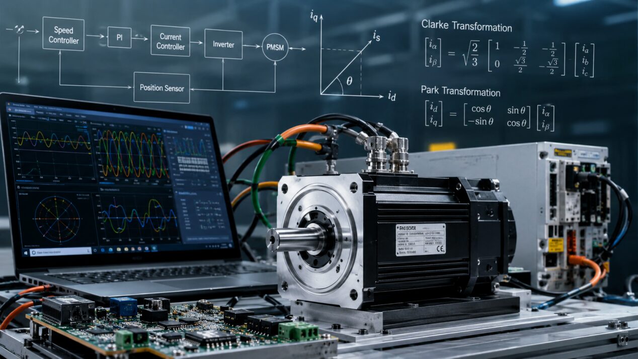
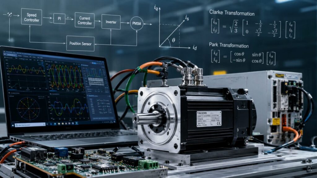
Figure 1: Conceptual overview of a field-oriented controlled electric motor drive system integrating PMSM, inverter, rotor position feedback, and dq-axis vector control framework
This figure 1 illustrates the overall concept of a modern electric motor drive system based on field-oriented control (FOC). The image represents the interaction between the permanent magnet synchronous motor (PMSM), power inverter, control algorithm, and feedback measurement system. The control structure highlights the transformation of three-phase motor currents into the rotating dq reference frame through Clarke and Park transformations, enabling independent control of flux and torque components. The integration of real-time monitoring, current regulation, and rotor position estimation demonstrates how vector control improves motor responsiveness, efficiency, and dynamic performance in advanced electric drive applications.
Vector control, introduced through field-oriented control principles, overcomes these limitations by transforming the three-phase motor quantities into a rotating reference frame aligned with the rotor magnetic field. In this coordinate system, the AC motor behaves similarly to a separately excited DC motor, where one current component controls flux and another independently controls torque [2]. This transformation enables precise control of motor electromagnetic behavior and has become the foundation of modern high-performance electric drives.
The objective of this research is to analyze the operating principles, mathematical foundations, control architecture, implementation challenges, and validation methods of FOC-based electric motor systems. A MATLAB-based simulation framework is developed to demonstrate the complete vector control process including reference frame transformations, closed-loop current regulation, speed control, PWM generation, sensorless estimation, field weakening operation, thermal analysis, and fault handling.
II. Why Vector Control Defines Modern Motor Performance
Vector control is not simply an additional software layer applied to an electric motor; it represents the core mechanism that determines how accurately the machine responds to operating commands. In modern drive applications, the perceived quality of a motor system is directly related to the performance of its control strategy. Smooth acceleration, precise positioning, low acoustic noise, reduced vibration, and high efficiency are achieved through accurate electromagnetic control rather than motor construction alone.
Traditional scalar V/f control maintains a nearly constant ratio between voltage and frequency to preserve air-gap flux. Although this method is simple and computationally inexpensive, it assumes steady-state operation and cannot compensate effectively for transient disturbances. During rapid speed changes or sudden load variations, the relationship between flux and torque becomes inaccurate, resulting in slow dynamic response and increased losses [3].
The primary limitation of AC machines is that torque cannot be controlled directly because the stator currents are sinusoidal and continuously changing in magnitude and phase. Unlike a DC motor where field flux and armature current are naturally separated, AC motors contain coupled magnetic components. Without mathematical transformation, modifying current amplitude changes both torque and flux simultaneously.
FOC solves this problem by converting the stationary three-phase system into a synchronously rotating dq coordinate system. The d-axis component is aligned with the rotor magnetic field and controls flux generation, while the q-axis component produces electromagnetic torque. Through this separation, the controller can independently regulate motor torque and magnetic flux, resulting in fast response and improved efficiency [4].
The quality of vector control directly influences the overall motor performance. Accurate rotor position estimation, optimized current regulation, and properly tuned controllers allow the motor to achieve smooth operation over a wide speed range. Therefore, modern electric drive systems rely on control algorithms as much as electromagnetic machine design.
III. Mathematical Foundation of Field-Oriented Control
Field-oriented control is based on transforming three-phase electrical quantities into a rotating reference frame where machine variables become easier to control. The transformation process consists mainly of Clarke transformation and Park transformation.
The Clarke transformation is mathematically represented as [5]:
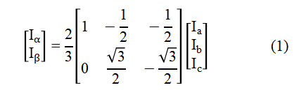
where Ia, Ib, and Ic represent the instantaneous three-phase stator currents, while Iα and Iβ denote the equivalent orthogonal current components in the stationary reference frame.
After the Clarke transformation, the Park transformation rotates the stationary αβ coordinate system into the synchronously rotating dq reference frame aligned with the rotor magnetic field. This transformation eliminates the sinusoidal variation of AC quantities and converts them into approximately constant DC values, which simplifies closed-loop controller design. The Park transformation is given as [6]:

where Id represents the direct-axis current component responsible for controlling the rotor flux, Iq represents the quadrature-axis current component responsible for torque generation, and θe is the electrical rotor angle used for reference frame alignment.
In the dq rotating reference frame, the AC motor behaves similarly to a separately excited DC motor because flux and torque-producing components become independently controllable. For a permanent magnet synchronous motor (PMSM), electromagnetic torque is mainly controlled through the quadrature-axis current component and is expressed as [11]:
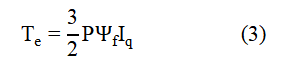
where Te is the electromagnetic torque, PPP is the number of rotor pole pairs, Ψf is the permanent magnet flux linkage, and Iq is the torque-producing current component. Equation (3) demonstrates the fundamental advantage of FOC, where torque can be directly regulated by controlling the q-axis current while maintaining flux independently through the d-axis component. Therefore, vector control enables AC machines to achieve the controllability and dynamic performance characteristics traditionally associated with DC motors.
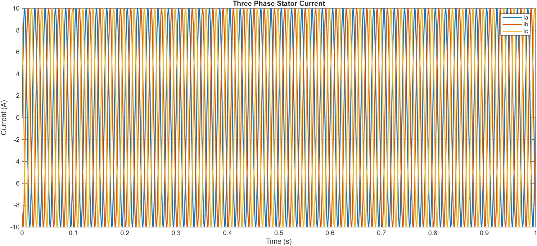
Figure 2: Three-phase stator current waveforms of PMSM drive system
Figure 2 presents the balanced three-phase stator current waveforms generated by the motor drive system. The three sinusoidal currents Ia, Ib, and Ic are displaced by 120 electrical degrees, representing the fundamental operating principle of AC machines. These phase currents contain both torque-producing and flux-producing components, which cannot be independently controlled in the stationary reference frame. Therefore, coordinate transformation is required to convert these coupled quantities into a rotating reference frame suitable for vector control.
The Clarke transformation converts the three-phase stationary abc system into a two-axis stationary αβ coordinate system. A balanced three-phase current system contains redundant information because the sum of the three currents is zero. Therefore, the Clarke transformation reduces the three-phase system into two orthogonal components while maintaining the electromagnetic information of the machine [5].
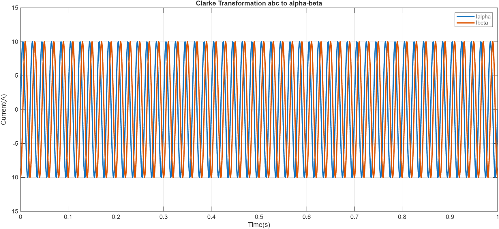
Figure 3: Clarke transformation of three-phase currents into stationary αβ reference frame
Figure 3 illustrates the Clarke transformation process where the three-phase abc current system is converted into a two-axis stationary αβ coordinate system. This transformation reduces the mathematical complexity while preserving the electromagnetic information of the motor. The obtained α-axis and β-axis current components are then used as inputs for the Park transformation stage of the FOC algorithm.
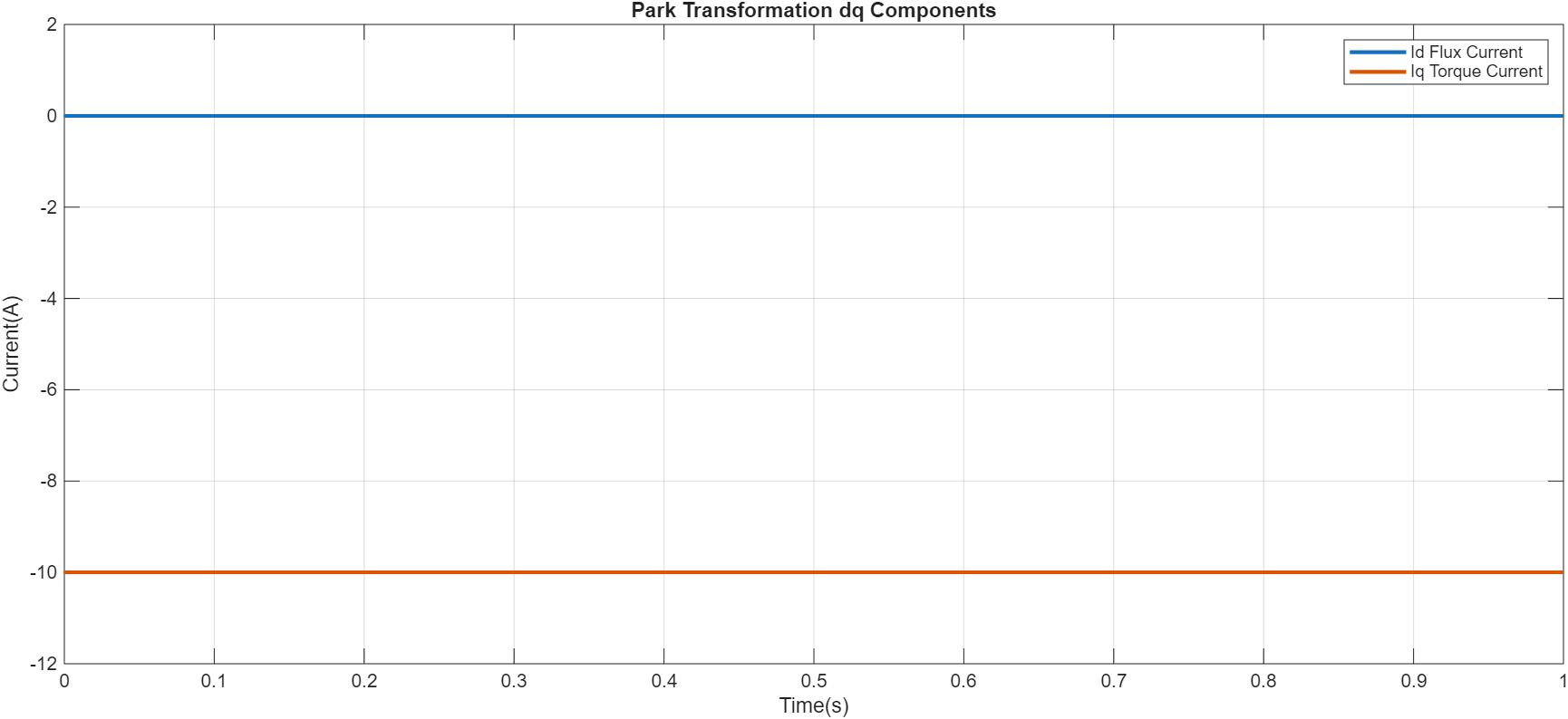
Figure 4: Park transformation showing d-axis flux and q-axis torque current components
Figure 4 demonstrates the conversion of stationary αβ currents into the rotating dq reference frame using the Park transformation. The d-axis current represents the magnetic flux-producing component, while the q-axis current controls electromagnetic torque generation. This separation allows the AC motor to behave similarly to a separately excited DC motor, enabling independent torque and flux control.
IV. Core Control Structure of FOC Systems
A typical field-oriented control system is implemented as a hierarchical closed-loop control structure consisting of an outer speed regulation loop and inner current regulation loops. The main objective of this architecture is to generate the required torque while maintaining accurate flux control and stable motor operation. The outer speed controller determines the required torque-producing current reference, whereas the inner current controllers regulate the d-axis and q-axis currents generated by the reference frame transformation. This cascaded structure provides fast torque response while maintaining accurate speed tracking under dynamic operating conditions [7].
In the developed MATLAB model, the FOC architecture consists of a speed controller, dq current controllers, decoupling compensation, inverse transformations, and a PWM inverter stage. The rotor position information is used to align the rotating coordinate system with the rotor magnetic field, allowing independent control of flux and torque components.
A. Current Control Loops
The inner current control loop is the fastest control layer in an FOC system. Its main function is to force the actual d-axis and q-axis currents to follow their respective reference values. Since torque response is directly associated with q-axis current, the current controller determines the dynamic behavior of the motor drive.
Proportional-integral (PI) controllers are commonly used for dq current regulation because the transformed currents appear as DC quantities in the rotating reference frame. The proportional component provides rapid correction during transient conditions, while the integral component eliminates steady-state error caused by resistance variations and load disturbances [8].
The d-axis current reference is generally maintained at zero for surface-mounted permanent magnet synchronous motors (PMSM), because flux is already provided by the permanent magnets. The q-axis current reference is generated from the required torque command. By controlling these two currents independently, the motor can achieve accurate torque production with minimum losses.
Practical FOC implementations include current saturation and anti-windup mechanisms to prevent controller instability during high torque demands. When the inverter voltage limit is reached, the PI integrators must be restricted to avoid excessive accumulation that can cause overshoot and slow recovery.
The MATLAB simulation demonstrates this behavior through the dq current regulation response, where the d-axis current remains near zero while the q-axis current follows the torque command. This confirms the successful separation of flux and torque control.
B. Speed and Torque Control
The outer speed control loop determines the overall dynamic performance of the electric drive. The speed error between the reference command and measured motor speed is processed through a PI controller to generate the torque reference. This torque reference is converted into the q-axis current command according to the motor torque equation.
The speed controller operates at a slower sampling rate compared with the current controller because mechanical dynamics are significantly slower than electrical dynamics. This separation improves controller stability and allows rapid torque correction without disturbing speed regulation [9].
During acceleration, the controller increases q-axis current to produce higher electromagnetic torque. When the motor approaches the desired speed, the torque command decreases to balance mechanical losses and load torque. Under sudden load changes, the speed controller automatically modifies the torque reference to maintain constant speed.
The simulation results show that FOC provides fast speed tracking with minimal overshoot compared with conventional scalar control. The ability to directly regulate torque allows the motor to quickly respond to reference changes and disturbances.
C. Reference Frame Generation
Accurate reference frame generation is essential for successful vector control because all dq control operations depend on the rotor electrical angle. The transformation angle determines the alignment between the rotating coordinate system and the rotor magnetic field.
In sensor-based systems, rotor position is measured using encoders, resolvers, or Hall sensors. These sensors provide accurate position feedback, especially at zero and low speeds where sensorless methods become challenging. However, they increase hardware cost, require additional wiring, and may reduce system reliability in harsh environments [10].
In sensorless control systems, rotor position is estimated using electrical quantities such as back electromotive force (back-EMF), flux observers, or high-frequency signal injection techniques. Sensorless approaches reduce hardware complexity and improve reliability but introduce estimation errors, particularly during startup and low-speed operation.
Incorrect rotor angle estimation produces dq-axis misalignment, causing unwanted coupling between flux and torque currents. Even small angle errors can increase losses, reduce efficiency, and create torque ripple. Therefore, accurate rotor position tracking remains one of the most critical aspects of FOC implementation.
V. FOC in PMSM, ASM, and Reluctance Machines
Although vector control principles are similar for different electric machines, the implementation depends strongly on the electromagnetic characteristics of the motor. Each machine type requires specific control strategies to achieve optimal performance.
Permanent magnet synchronous motors (PMSMs) are among the most common machines controlled using FOC due to their high efficiency, high power density, and excellent dynamic response. In PMSM drives, rotor flux is produced by permanent magnets, allowing torque control primarily through q-axis current. For normal operation, the d-axis current is maintained close to zero. During high-speed operation, negative d-axis current is applied to weaken the magnetic field and extend the operating speed range [11].
Induction machines (asynchronous motors) require a more complex vector control approach because rotor flux is not directly available. Instead, rotor flux must be estimated using motor parameters such as resistance, inductance, and slip frequency. The controller aligns the reference frame with the estimated rotor flux vector, enabling independent torque and flux control. However, induction motor FOC is more sensitive to parameter variations, especially rotor resistance changes caused by temperature.
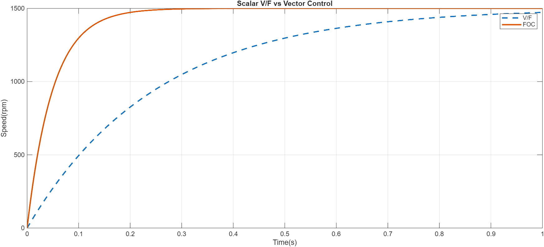
Figure 5: Comparison between scalar V/f control and field-oriented vector control response
Figure 5 compares the dynamic response of conventional scalar V/f control with advanced field-oriented control. The scalar method provides slower speed response because torque and flux cannot be controlled independently. In contrast, FOC achieves faster response due to direct regulation of dq-axis currents, demonstrating improved transient performance and accuracy.
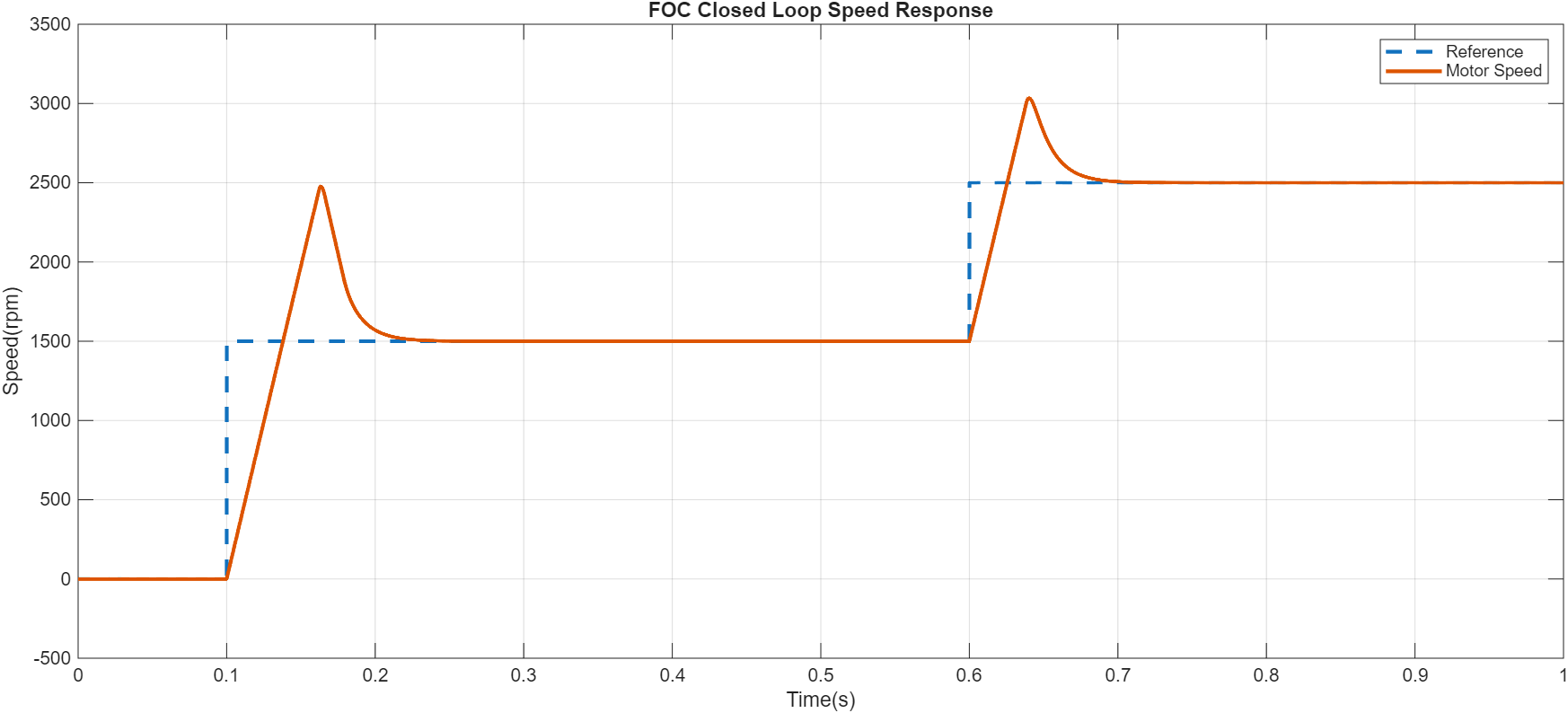
Figure 6: FOC closed loop speed response output graphs which provide reference and motor speed curve
Figure 6 presents the closed-loop speed control performance of the FOC system. The reference speed command is compared with the actual motor speed, and the PI speed controller generates the required torque reference. The close tracking between reference and measured speed demonstrates effective regulation and disturbance rejection capability.
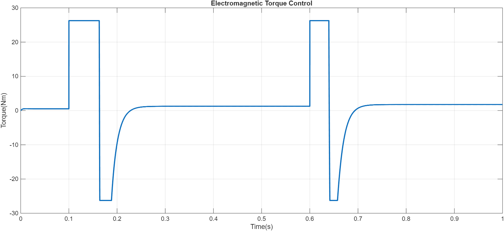
Figure 7: Electromagnetic Torque control output graph
Figure 7 shows the electromagnetic torque response obtained through q-axis current regulation. Since torque in PMSM drives is directly proportional to q-axis current, controlling this component enables accurate torque production. The result confirms the effectiveness of vector control in achieving fast torque dynamics.
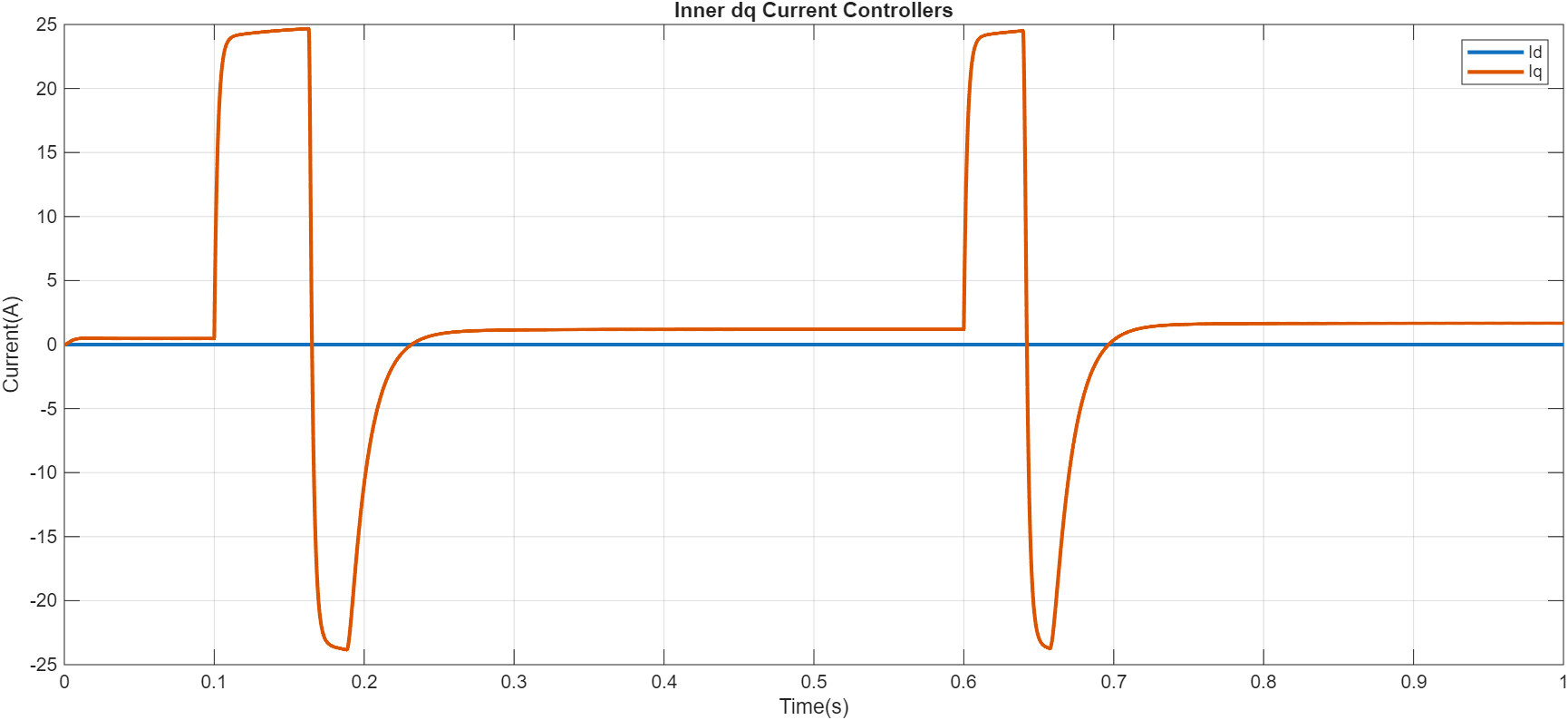
Figure 8: Inned dq current controllers curves
Figure 8 illustrates the performance of the inner current controllers responsible for regulating the flux and torque components. The d-axis current maintains flux control while the q-axis current follows the torque command. The PI controllers minimize current tracking errors and provide fast electrical response.
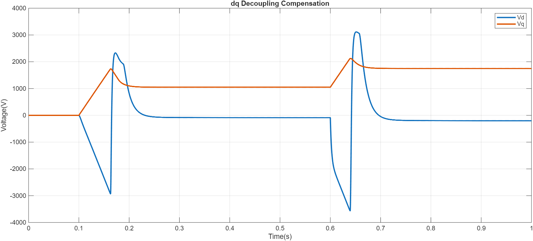
Figure 9: dq decoupling compensation which provided Vd and Vq output graphs
You can download the Project files here: Download files now. (You must be logged in).
Figure 9 shows the decoupling compensation voltages applied to the d and q axes. Due to rotor rotation, coupling terms appear between the two axes. The compensation terms cancel these effects and improve current controller performance by maintaining independent flux and torque regulation.
Synchronous reluctance motors (SynRM) produce torque through magnetic saliency rather than permanent magnets. In these machines, torque generation depends on the difference between d-axis and q-axis inductances. Vector control regulates current components to maximize the saliency torque while minimizing losses. Compared with PMSM systems, SynRM control requires accurate inductance estimation because torque production depends strongly on machine geometry.
Therefore, vector control is not a universal algorithm applied identically to every motor. The control strategy must be adapted according to the physical torque generation mechanism of the machine.
VI. Sensor-Based and Sensorless Control
Rotor position feedback is a fundamental requirement in vector-controlled motor drives because the transformation angle determines the accuracy of the dq reference frame. Two major approaches are used: sensor-based control and sensorless control.
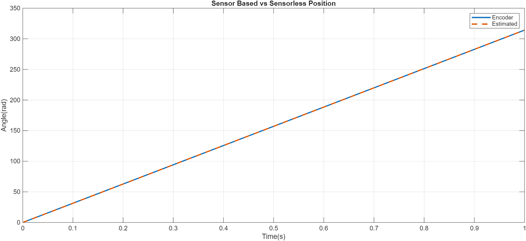
Figure 10: Comparison of sensor-based and sensorless rotor position estimation
Figure 10 compares the measured rotor position obtained from a sensor with the estimated position generated by the sensorless algorithm. The estimated position closely follows the actual rotor angle, demonstrating the feasibility of eliminating mechanical position sensors while maintaining acceptable control accuracy.
A. Sensor-Based Control
Sensor-based FOC systems use physical measurement devices such as encoders, resolvers, and Hall-effect sensors. These sensors provide direct rotor position and speed information, enabling accurate transformation and control.
Encoders provide high-resolution digital position measurement and are widely used in precision applications such as robotics and CNC machines. Resolvers provide robust operation in high-temperature and industrial environments due to their electromagnetic construction. Hall sensors are simpler and cheaper but provide limited resolution.
The major advantage of sensor-based control is accurate operation at zero and low speeds. Since rotor position is directly measured, startup torque generation and low-speed stability are significantly improved. However, the additional hardware increases cost, system complexity, and potential failure points.
B. Sensorless Control
Sensorless FOC eliminates mechanical position sensors by estimating rotor position from electrical signals. Common techniques include back-EMF estimation, sliding-mode observers, extended Kalman filters, and high-frequency injection methods [12].
Back-EMF methods are effective at medium and high speeds because induced voltage increases with rotor velocity. However, during startup and low-speed operation, back-EMF magnitude becomes very small, making estimation difficult.
High-frequency signal injection methods overcome this limitation by applying additional excitation signals to detect rotor position from magnetic saliency. These methods provide improved low-speed performance but increase computational requirements.
The selection between sensor-based and sensorless control depends on application requirements. High-performance systems often use sensors for maximum accuracy, while cost-sensitive applications prefer sensorless approaches.
VII. Field Weakening and High-Speed Operation
The maximum operating speed of an electric motor is limited by the available DC bus voltage. At high speeds, the back electromotive force increases and eventually approaches the inverter voltage limit. Beyond this point, additional speed increase becomes impossible unless the magnetic flux is reduced.
Field weakening extends the motor operating range by applying negative d-axis current. The negative Id component opposes the permanent magnet flux, reducing the effective air-gap flux and allowing operation above base speed [13].
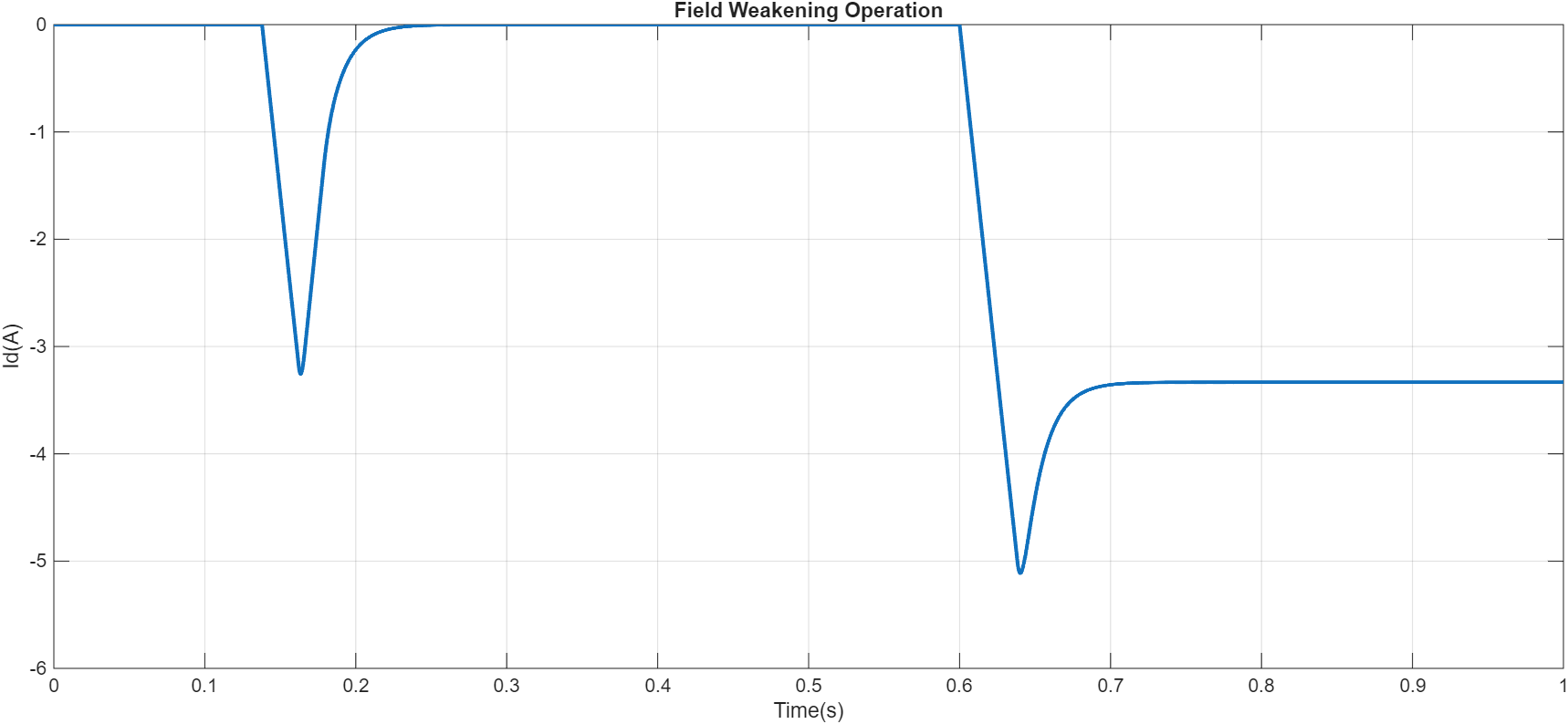
Figure 11: Negative d-axis current operation for field weakening control
Figure 11 demonstrates field weakening operation beyond the motor base speed. A negative d-axis current is applied to reduce the effective magnetic flux, allowing the motor to operate at higher speeds under inverter voltage limitations. This technique extends the usable speed range while maintaining controlled torque production.
During field weakening, the controller maintains the required torque by increasing q-axis current while reducing magnetic flux. However, this introduces additional copper losses because higher current is required. Furthermore, excessive field weakening can increase thermal stress and demagnetization risk in permanent magnet machines.
The MATLAB simulation demonstrates field weakening operation by introducing negative d-axis current when the motor speed exceeds the base speed. This allows continued operation under voltage limitations while maintaining controlled torque production.
VIII. Dynamic Behavior and Control Stability
The performance of a vector-controlled motor drive depends not only on the control structure but also on the stability of the system under changing operating conditions. A well-designed FOC system must maintain accurate torque and speed regulation despite variations in electrical parameters, mechanical loading, and environmental conditions.
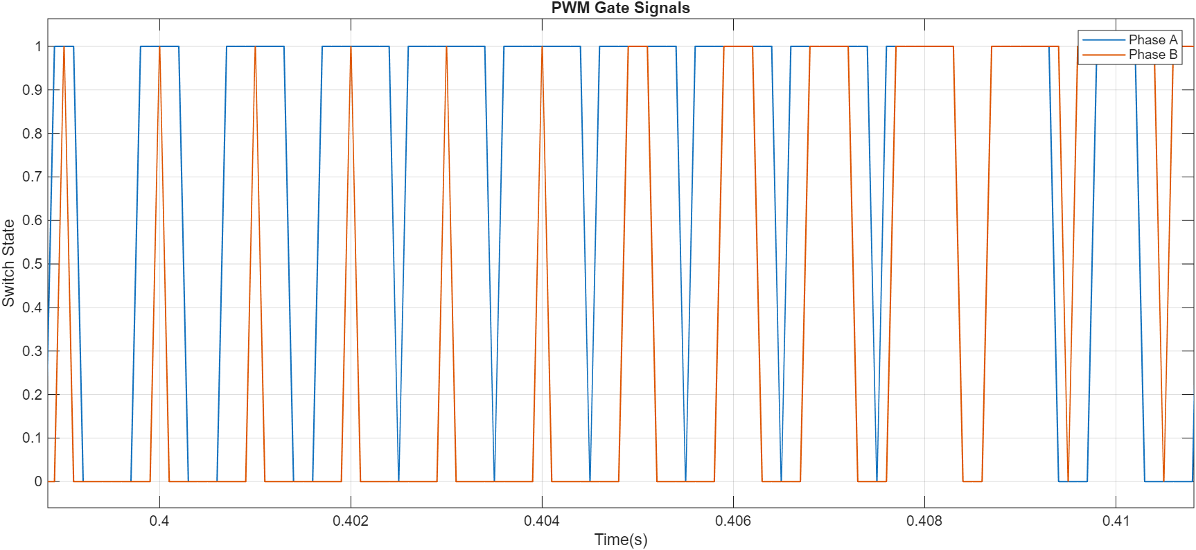
Figure 12: PWM switching signals generated for inverter phase control
You can download the Project files here: Download files now. (You must be logged in).
Figure 12 presents the PWM gate signals generated by the FOC controller for inverter operation. These switching signals control the power semiconductor devices and convert the DC-link voltage into controlled three-phase AC voltages applied to the motor. Accurate PWM generation is essential for achieving low current ripple and efficient motor operation.
The main parameters affecting FOC performance include stator resistance, inductances, rotor flux linkage, and mechanical inertia. These parameters are often considered constant during controller design; however, practical operating conditions introduce variations. For example, stator resistance increases with temperature, which changes voltage requirements and affects current regulation accuracy. Similarly, magnetic saturation can modify inductance values, causing mismatch between the motor model and actual machine behavior [14].
Another important challenge is cross-coupling between d-axis and q-axis dynamics. Although the Park transformation separates flux and torque components, the rotating reference frame introduces coupling terms caused by electrical speed. These terms appear in the dq voltage equations and can reduce controller performance if not compensated. Therefore, decoupling control is commonly introduced to cancel these effects and improve dynamic response.
PI controller tuning also plays a critical role in system stability. Excessive proportional gain may produce fast response but can cause oscillation, while insufficient gain results in slow tracking. The integral gain must be carefully selected to remove steady-state errors without causing excessive overshoot. Additionally, saturation handling is required because inverter voltage and motor current have physical limitations.
The simulation results confirm that the developed FOC system maintains stable operation during speed transitions and load disturbances. The torque controller rapidly compensates for load variations, demonstrating the robustness of vector control under dynamic conditions.
IX. FOC Implementation in Real-Time Systems
Although FOC concepts are commonly developed using simulation environments, practical implementation requires consideration of embedded hardware limitations and real-time execution constraints. Modern electric drives are typically implemented using microcontrollers (MCUs), digital signal processors (DSPs), or field-programmable gate arrays (FPGAs) capable of executing control algorithms within strict timing requirements.
Model-based design approaches using platforms such as MATLAB/Simulink allow engineers to develop motor models, tune controllers, generate embedded code, and validate algorithms before hardware implementation. This reduces development time and allows control strategies to be verified under different operating conditions.
The execution speed of the control algorithm must match the motor electrical dynamics. The current control loop generally operates at a high sampling frequency, often synchronized with inverter switching frequency. Faster sampling provides improved current regulation but increases computational requirements.
The inverter stage converts the controller-generated voltage references into switching signals using pulse width modulation (PWM). The PWM duty cycles determine the average phase voltages applied to the motor. Proper synchronization between PWM generation and current measurement is required to minimize noise and improve control accuracy.
Embedded implementation also requires optimization because processors have limited memory and computational resources. Efficient mathematical operations, lookup tables, fixed-point calculations, and optimized transformation algorithms are commonly used to achieve real-time performance.
X. Validation Through Simulation and Testing
Before deployment in real applications, vector control algorithms must undergo extensive validation under realistic operating conditions. Simulation provides a safe environment for testing controller performance before hardware implementation.
A. Simulation Stage
The simulation stage involves mathematical modeling of the motor, inverter, controller, and mechanical load. Two major modeling approaches are commonly used: average-value models and detailed switching models.
Average models simplify inverter behavior by representing switching devices as ideal voltage sources. These models require less computation and are useful for controller tuning and system-level studies. Detailed switching models include semiconductor switching behavior and provide more realistic results but require higher computational effort.
The MATLAB simulation developed in this work includes a PMSM model, coordinate transformations, PI controllers, PWM generation, and protection logic. The simulation evaluates speed response, torque generation, current regulation, efficiency, thermal behavior, and fault conditions.
The obtained results demonstrate that FOC achieves accurate speed tracking and effective torque control. The dq current response confirms the separation between flux and torque components, while the field weakening results verify high-speed operation capability.
B. Hardware Testing
After simulation verification, the control algorithm is typically tested using hardware-in-the-loop (HIL) or inverter-in-the-loop platforms. These methods allow real-time testing of the controller without exposing the physical motor to unsafe conditions.
HIL testing combines a real controller with a simulated motor model running on a real-time processor. This approach allows engineers to evaluate control performance, timing limitations, and fault handling strategies.
Final experimental testing involves operating the motor under real mechanical loads. During this stage, parameter mismatches, sensor errors, thermal effects, and mechanical vibrations can be identified and corrected.
XI. Interaction Between Control, Thermal, and Mechanical Domains
An electric drive system is a combination of electrical, electromagnetic, thermal, and mechanical subsystems. Therefore, optimizing only the control algorithm is insufficient for achieving maximum system performance.
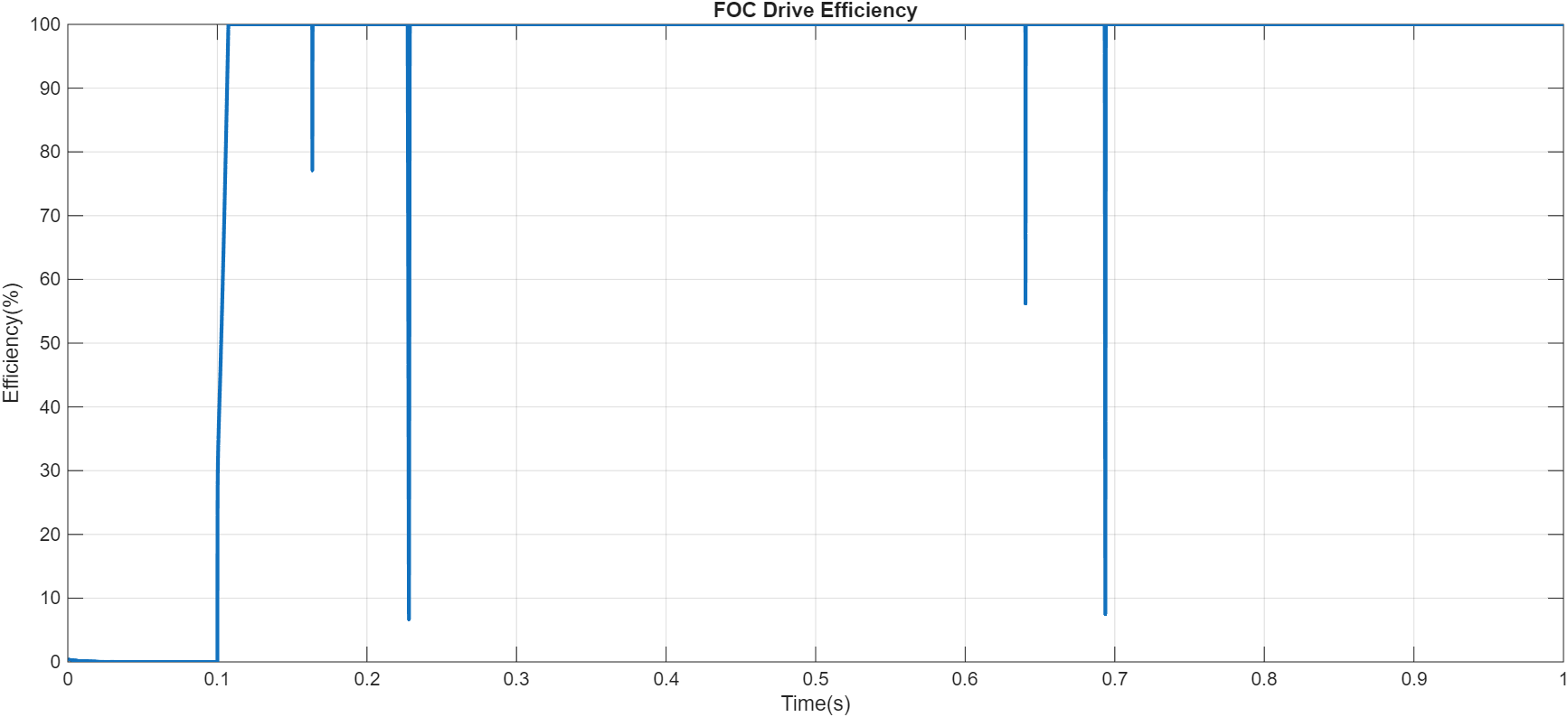
Figure 13: FOC Drive Efficiency output graph
Figure 13 shows the calculated efficiency performance of the FOC-controlled motor system. The efficiency depends on copper losses, current magnitude, and operating speed. Proper flux and torque control reduces unnecessary current consumption and improves overall energy conversion efficiency.
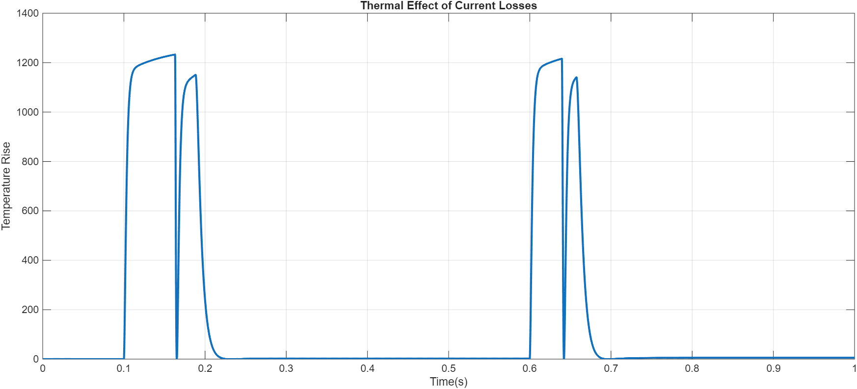
Figure 14: Thermal effect of current losses output graph
Figure 14 presents the temperature rise resulting from copper losses in the motor windings. Since electrical losses increase with the square of current, aggressive torque commands can increase thermal stress. Therefore, thermal considerations must be integrated with motor control design.
Higher current demands increase winding temperature and may reduce motor lifetime. Similarly, inverter switching losses increase with higher switching frequency and current ripple.
Torque ripple produced by imperfect current regulation or inaccurate rotor position estimation can create mechanical vibration and acoustic noise. These effects are especially important in automotive and precision motion applications where noise, vibration, and harshness (NVH) performance are critical.
Aggressive control tuning improves response speed but may increase losses due to higher current demand and rapid switching actions. Therefore, modern FOC systems require a balance between dynamic performance and efficiency.
Field weakening operation also affects thermal behavior because negative d-axis current increases total stator current while reducing magnetic flux. Therefore, high-speed operation requires coordination between electromagnetic design, thermal management, and control optimization.
XII. Safety, Compliance, and Fault Handling
Modern electric drive systems must operate safely under abnormal conditions. Protection mechanisms are integrated into FOC systems to prevent damage to power electronics, motors, and connected equipment.
Overcurrent protection is one of the most important safety features. Excessive current can result from short circuits, controller malfunction, or mechanical overload. The control system continuously monitors phase currents and disables inverter operation when limits are exceeded.
Overvoltage protection prevents damage caused by DC-link voltage rise during regenerative braking or sudden load changes. Voltage monitoring circuits detect abnormal conditions and activate protective actions.
Sensor failures are another critical concern. Loss of encoder feedback or incorrect position measurement can cause unstable control. Fault detection algorithms compare measured and estimated signals to identify sensor problems and switch to safe operating modes.
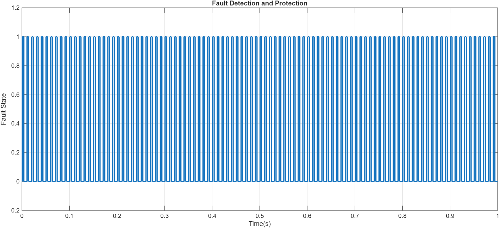
Figure 15: Fault detection and protection output graph
Figure 15 demonstrates the implemented fault monitoring system for detecting abnormal operating conditions. The controller monitors current and voltage limits and generates a protection signal when unsafe conditions occur. This improves drive reliability and prevents damage to power electronics and motor components.
In automotive and safety-critical applications, functional safety standards such as ISO 26262 require reliable fault handling mechanisms. Safe Torque Off (STO) is commonly implemented to immediately disable torque generation during emergency conditions [15].
Fault-tolerant control strategies allow continued operation under degraded conditions by adjusting control parameters or switching to alternative estimation methods.
XIII. Results and Discussion
The developed MATLAB-based FOC simulation successfully demonstrates the complete operation of a modern electric motor control system. The Clarke transformation converts the three-phase stator currents into stationary orthogonal components, while the Park transformation further converts these signals into the rotating dq reference frame. This transformation enables independent regulation of flux and torque components.
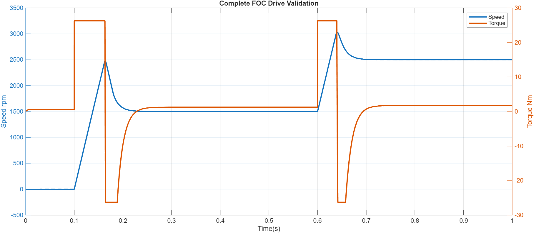
Figure 16: Complete FOC Drive Validation which provided Speed and Torque graphs
You can download the Project files here: Download files now. (You must be logged in).
Figure 16 summarizes the overall performance of the developed FOC drive system by showing the relationship between motor speed and electromagnetic torque. The results verify that the proposed control method provides stable speed tracking, accurate torque generation, and reliable dynamic performance under changing operating conditions.
The comparison between scalar V/f control and vector control shows that FOC provides significantly faster dynamic response because torque is directly controlled through q-axis current. The speed controller maintains accurate tracking during reference changes, while the current controllers regulate dq currents with minimal error.
The torque response demonstrates that electromagnetic torque follows the reference command effectively, confirming the direct relationship between q-axis current and torque generation. The field weakening results show successful operation beyond base speed through controlled negative d-axis current.
Sensorless estimation results demonstrate that rotor position can be accurately approximated without mechanical sensors, although small estimation errors exist during transient conditions. Efficiency and thermal analysis confirm that current control directly affects energy losses and temperature rise.
The protection analysis verifies that the implemented monitoring system can detect abnormal current and voltage conditions, improving drive reliability and safety.
XIV. Conclusion
This paper presented a detailed study of field-oriented control and vector control techniques for modern electric motor systems. Unlike conventional scalar control methods, FOC transforms the AC machine into a decoupled rotating reference frame where flux and torque can be independently controlled. This capability enables high-performance operation with improved efficiency, fast transient response, and accurate speed regulation.
The mathematical principles of Clarke and Park transformations were analyzed, demonstrating their importance in converting complex AC machine behavior into controllable dq-axis variables. A complete PMSM FOC simulation was developed including speed regulation, current control, PWM generation, field weakening, sensorless estimation, thermal analysis, and fault protection.
The results demonstrate that vector control is a fundamental technology enabling modern electric drive performance. Future improvements in sensorless estimation, artificial intelligence-based tuning, and integrated thermal-control optimization will further enhance the capability of electric motor systems.
References
[1] B. K. Bose, Modern Power Electronics and AC Drives, Prentice Hall, 2002.
[2] F. Blaschke, “The Principle of Field Orientation Applied to the New Transvector Closed-Loop Control System for Rotating Field Machines,” Siemens Review, vol. 34, pp. 217–220, 1972.
[3] R. Krishnan, Electric Motor Drives: Modeling, Analysis, and Control, Prentice Hall, 2001.
[4] P. Vas, Sensorless Vector and Direct Torque Control, Oxford University Press, 1998.
[5] C. C. Lee, “Fuzzy Logic in Control Systems: Fuzzy Logic Controller,” IEEE Transactions on Systems, Man, and Cybernetics, vol. 20, no. 2, pp. 404–435, 1990.
[6] J. Holtz, “Sensorless Control of Induction Motor Drives,” Proceedings of the IEEE, vol. 90, no. 8, pp. 1359–1394, 2002.
[7] R. H. Middleton and G. C. Goodwin, Digital Control and Estimation, Prentice Hall, 1990.
[8] K. J. Astrom and T. Hagglund, PID Controllers: Theory, Design, and Tuning, ISA, 1995.
[9] W. Leonhard, Control of Electrical Drives, Springer, 2001.
[10] A. Consoli, G. Scarcella, and A. Testa, “Sensorless Control of AC Motors,” IEEE Transactions on Industrial Electronics, vol. 41, no. 3, pp. 292–299, 1994.
[11] S. Morimoto, M. Sanada, and Y. Takeda, “Wide-Speed Operation of Interior Permanent Magnet Synchronous Motors,” IEEE Transactions on Industry Applications, vol. 30, no. 4, pp. 920–926, 1994.
[12] R. Dhaouadi, N. Mohan, and L. Norum, “Design and Implementation of an Extended Kalman Filter for the State Estimation of a Permanent Magnet Synchronous Motor,” IEEE Transactions on Power Electronics, vol. 6, no. 3, pp. 491–497, 1991.
[13] T. M. Jahns, “Flux-Weakening Regime Operation of an Interior Permanent-Magnet Synchronous Motor Drive,” IEEE Transactions on Industry Applications, vol. IA-23, no. 4, pp. 681–689, 1987.
[14] P. Pillay and R. Krishnan, “Modeling, Simulation, and Analysis of Permanent-Magnet Motor Drives,” IEEE Transactions on Industry Applications, vol. 25, no. 2, pp. 265–273, 1989.
[15] ISO 26262, Road Vehicles – Functional Safety Standard, International Organization for Standardization, 2018.
You can download the Project files here: Download files now. (You must be logged in).










Responses