

Real-Time Simulation and Control of a Dual Active Bridge DC/DC Converter for Battery Charging Applications Using PLECS RT Box
Author: Waqas Javaid
Abstract
This paper presents the modeling, simulation, control implementation, and real-time validation of a high-power Dual Active Bridge (DAB) DC/DC converter for battery charging applications using the PLECS simulation platform and PLECS RT Box. The developed system transfers up to 50 kW power from an 800 V DC source to a 200 V battery pack rated at 100 kWh. The proposed converter utilizes phase-shift modulation with a closed-loop PI current controller and feedforward compensation to achieve fast dynamic response and accurate current regulation. Oversampling and Moving Average Filtering (MAF) techniques are implemented to improve current measurement quality under high-frequency switching conditions. The plant and controller are implemented in separate subsystems, enabling both offline simulation and hardware-in-the-loop (HIL) real-time testing using two RT Boxes. Detailed mathematical modeling, controller design, PWM generation, and system linearization are discussed. Simulation and real-time results demonstrate accurate current tracking, stable converter operation, reduced ripple, and effective power transfer during charging and discharging conditions. The developed model provides an effective framework for rapid prototyping and validation of high-power isolated bidirectional converters for electric vehicle and battery energy storage applications.
I. Introduction
The increasing demand for electric vehicles, renewable energy systems, and battery energy storage systems has significantly increased the need for efficient bidirectional DC/DC converters. Among various converter topologies, the Dual Active Bridge (DAB) converter has become one of the most attractive solutions because of its galvanic isolation, bidirectional power transfer capability, soft-switching operation, and high-power density. DAB converters are widely used in electric vehicle charging stations, aircraft power systems, renewable energy integration, and medium-voltage DC grids.
The DAB converter consists of two full-bridge converters connected through a high-frequency transformer. Power transfer between the primary and secondary sides is controlled by adjusting the phase shift angle between the switching signals of the two bridges. This phase-shift modulation technique allows smooth and efficient power regulation without requiring complex duty-cycle control mechanisms.
In modern battery charging systems, accurate current regulation is essential to ensure battery safety, charging efficiency, and thermal stability. Therefore, advanced control strategies must be implemented to maintain stable converter operation under varying load and voltage conditions. Real-time simulation and hardware-in-the-loop validation are also becoming increasingly important for validating converter performance before hardware deployment [1].
This research presents the development of a complete DAB converter model using the PLECS simulation environment and PLECS RT Box platform. The proposed system includes [2][3]:
- Detailed DAB power-stage modeling
- Closed-loop current control using PI regulation
- Feedforward phase-shift compensation
- Oversampling and Moving Average Filtering
- Real-time implementation using two RT Boxes
- Offline and real-time simulation validation
The developed system demonstrates accurate current control, stable power transfer, and fast transient response suitable for battery charging applications.
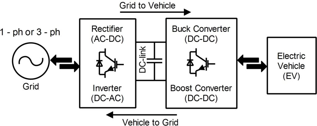
II. System Overview
The developed converter transfers energy from an 800 V DC source to a 200 V lithium-ion battery pack [4]. The converter is rated for 50 kW power transfer capability. The complete system consists of:
- DAB Power Stage
- Battery Model
- PI-Based Current Controller
- PWM Generation Unit
- Feedforward Controller
- Oversampling and Filtering Block
- Real-Time RT Box Interface
The entire model is divided into two separate subsystems:
- Plant subsystem
- Controller subsystem
This separation enables hardware-in-the-loop operation using two RT Boxes.
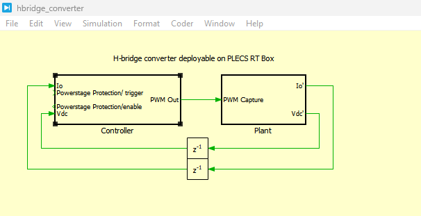
III. Top-Level Simulation Architecture
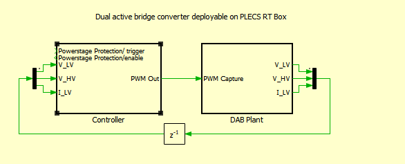
Figure 1 presents the top-level schematic of the developed DAB converter system implemented in PLECS. The system contains the DAB plant subsystem and controller subsystem connected through analog and PWM interfaces [6]. A delay block is included to model inherent digital control delays during offline simulation.
Figure 1: Top-level schematic of the DAB plant and controller model
The controller subsystem generates PWM switching pulses based on the measured current and voltage signals obtained from the plant model. The generated switching pulses are transmitted to the DAB converter to regulate power flow between the source and battery pack. The delay block accurately emulates practical implementation delays encountered in digital control systems [7].
IV. DAB Converter Plant Model
Figure 2 illustrates the detailed schematic of the DAB converter plant model implemented in PLECS.
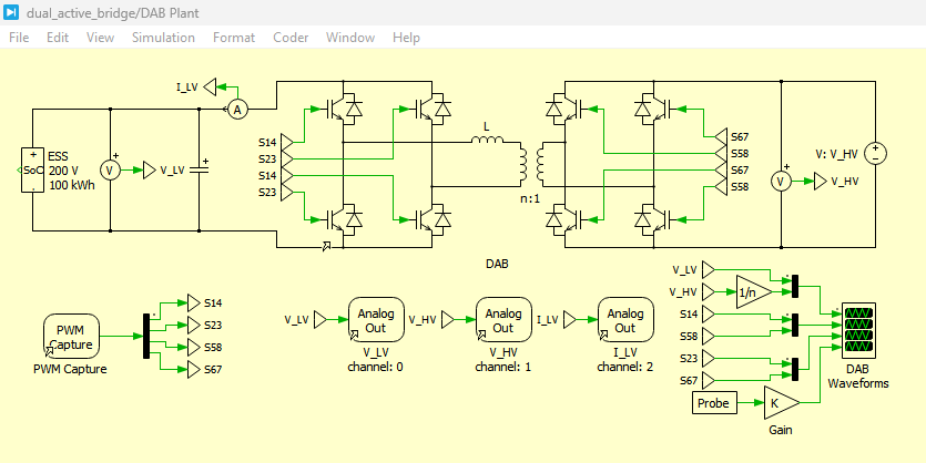
Figure 2: Schematic of the DAB plant model
The converter consists of two full-bridge converters connected through a medium-frequency transformer. The high-voltage side operates at 800 V while the low-voltage side interfaces with a 200 V battery pack [8].
The transformer leakage inductance plays a critical role in power transfer operation. The leakage inductance stores and transfers energy between the bridges according to the applied phase shift angle.
The developed model includes:
- Full-bridge converters
- Leakage inductance
- Transformer turns ratio
- Battery energy storage system
- Analog measurement blocks
- PWM capture blocks
The system operates at a switching frequency of 40 kHz.
V. Battery Modeling
The battery pack is modeled using Panasonic UR18650A lithium-ion cells. The selected cell parameters are summarized in Table I.
Table I: Parameters of the Developed DAB Converter System
| Parameter | Value |
| High-side Voltage | 800 V |
| Low-side Voltage | 200 V |
| Nominal Power | 50 kW |
| Leakage Inductance | 1.75 µH |
| Leakage Resistance | 100 mΩ |
| Switching Frequency | 40 kHz |
| Battery Capacity | 100 kWh |
The battery pack consists of:
- 56 cells connected in series
- 239 parallel branches
The developed battery model accurately reproduces charging and discharging characteristics under varying load conditions.
VI. Principle of DAB Operation
The DAB converter transfers power using phase-shift modulation between the two full bridges.
Figure 3 shows the operating waveforms of the DAB converter.
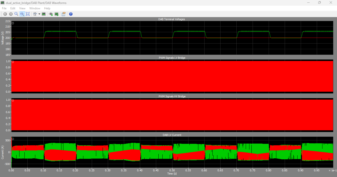
Figure 3: DAB voltage and current waveform during operation with PWM signals for HV and LV bridge.
The converter operates with constant duty-cycle switching signals while the phase shift between the primary and secondary bridge determines the transferred power.
When the phase shift angle increases, the transferred current also increases. Maximum power transfer occurs near a phase shift angle of π/2.
The average low-voltage side current is mathematically expressed as [1][2]:
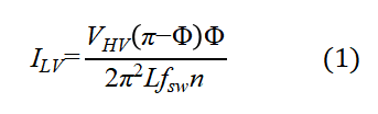
Where:
- I_LV= average low-voltage side current
- V_HV= high-voltage side DC voltage
- Φ= phase-shift angle
- L= transformer leakage inductance
- f_SW= switching frequency
- n= transformer turns ratio
The above equation 1 shows that the transferred current is a nonlinear function of phase shift angle.
VII. Current-Phase Shift Characteristics
Figure 4 illustrates the nonlinear relationship between phase shift angle and output current.
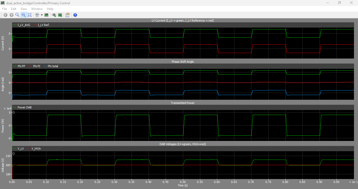
Figure 4: Nonlinear current-phase shift, transmitted power and DAB voltages relationship
The graph demonstrates that the output current increases nonlinearly as the phase shift angle increases. Initially, the current rises almost linearly, but nonlinear behavior becomes dominant near higher phase-shift values.
The system is linearized around the nominal operating point to simplify controller design.
The small-signal model is expressed as [1][3]:

Where:
- ΔI_LV= small-signal current variation
- ΔΦ= phase-shift variation
- K_DAB= DAB current gain
This linearized model is used for PI controller tuning.
VIII. Controller Design
Figure 5 presents the complete controller implementation used in the developed system.
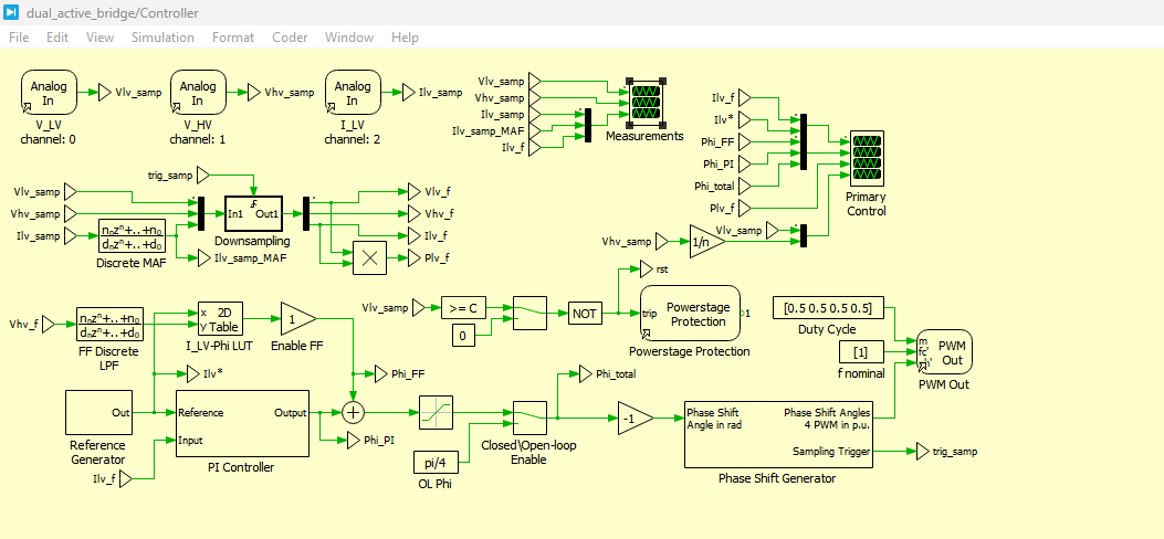
Figure 5: Controller implementation schematic
You can download the Project files here: Download files now. (You must be logged in).
The controller includes:
- Current sampling
- Moving Average Filter
- Feedforward controller
- PI current regulator
- PWM generation block
- Phase-shift generator
The main objective of the controller is to regulate battery charging current accurately under varying operating conditions.
The PI controller output determines the required phase-shift angle between the bridge switching signals.
IX. Oversampling and Moving Average Filter
Because the converter operates at high switching frequency, the measured current contains high ripple components. Therefore, oversampling and filtering techniques are required.
Figure 6 illustrates the oversampling implementation.
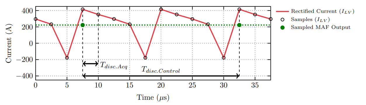
Figure 6: Oversampling and averaging of converter current
The current is sampled ten times during each switching cycle using a 2.5 µs acquisition interval. The Moving Average Filter removes switching ripple and provides an accurate average current value for controller operation. The Moving Average Filter (MAF) implemented for oversampling is based on the discrete filtering approach presented in [4].
The Moving Average Filter transfer function is [4]:
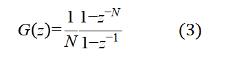
Where:
- N= number of samples per switching cycle
The filtering process significantly improves controller stability and measurement accuracy.
X. PWM Generation and Phase Shift Control
Figure 7 presents the phase-shift PWM generation subsystem.
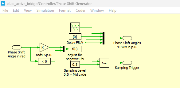
Figure 7: Phase-shift PWM generation subsystem
The PWM signals are generated using variable phase-shift carriers. The system produces four PWM signals for the two full-bridge converters. The phase-shift angle normalization method follows the implementation approach described in the PLECS RT Box documentation [5].
The phase shift angle is converted into per-unit form using [5]:
This implementation allows both positive and negative phase-shift operation for bidirectional power transfer.
XI. Feedforward Control Design
To improve transient response, a feedforward controller is implemented. The feedforward compensation equation is derived from the DAB nonlinear current transfer characteristics discussed in [1].
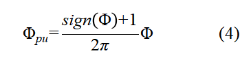
The feedforward phase-shift angle is computed using:

Where:
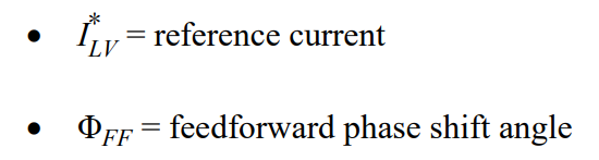
The feedforward controller provides an initial estimate of the required phase shift, while the PI controller compensates for modeling errors and disturbances.
XII. PI Controller Tuning
The controller is tuned using zero-pole cancellation methodology. The closed-loop transfer function of the PI-controlled converter is derived using the control methodology presented in [6].
The closed-loop transfer function is:
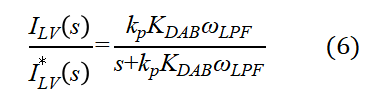
The PI controller parameters are calculated using pole-zero cancellation techniques described in [6]. The proportional and integral gains are selected using:
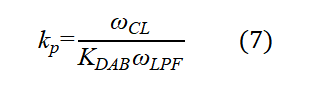
and
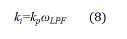
Where:
- Kp= proportional gain
- Ki= integral gain
- ωCL= closed-loop bandwidth
- ωLPF= filter cutoff frequency
The controller is designed for a 400 Hz bandwidth.
XIII. Real-Time RT Box Configuration
Figure 8 shows the hardware configuration used for real-time implementation.
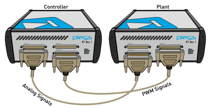
Figure 8: RT Box hardware configuration
You can download the Project files here: Download files now. (You must be logged in).
Two RT Boxes are interconnected using analog and digital interfaces.
- RT Box 1 executes the plant model
- RT Box 2 executes the controller model
The analog signals transmit voltage and current measurements while digital PWM signals control the DAB converter operation.
This setup enables accurate hardware-in-the-loop validation of converter performance.
XIV. Simulation Results
Extensive simulations were performed in PLECS to validate the developed DAB converter and control system under various charging and discharging conditions.
The simulation results demonstrate stable converter operation, fast current tracking, accurate phase-shift control, and efficient bidirectional power transfer between the high-voltage DC source and low-voltage battery pack. The developed PI controller combined with feedforward compensation successfully regulates the battery charging current while maintaining stable voltage levels across both converter terminals.
The converter operates at a switching frequency of 40 kHz with a discretization step size of 2.5 µs. Oversampling and Moving Average Filtering significantly improve the quality of measured current signals and reduce switching ripple effects in the feedback loop [9].
The system was tested under both positive and negative current references to evaluate charging and discharging operation. The simulation results confirm that the developed controller maintains stable operation even during sudden reference transitions and dynamic load changes.
XV. Analysis of Converter Voltage and Current Waveforms
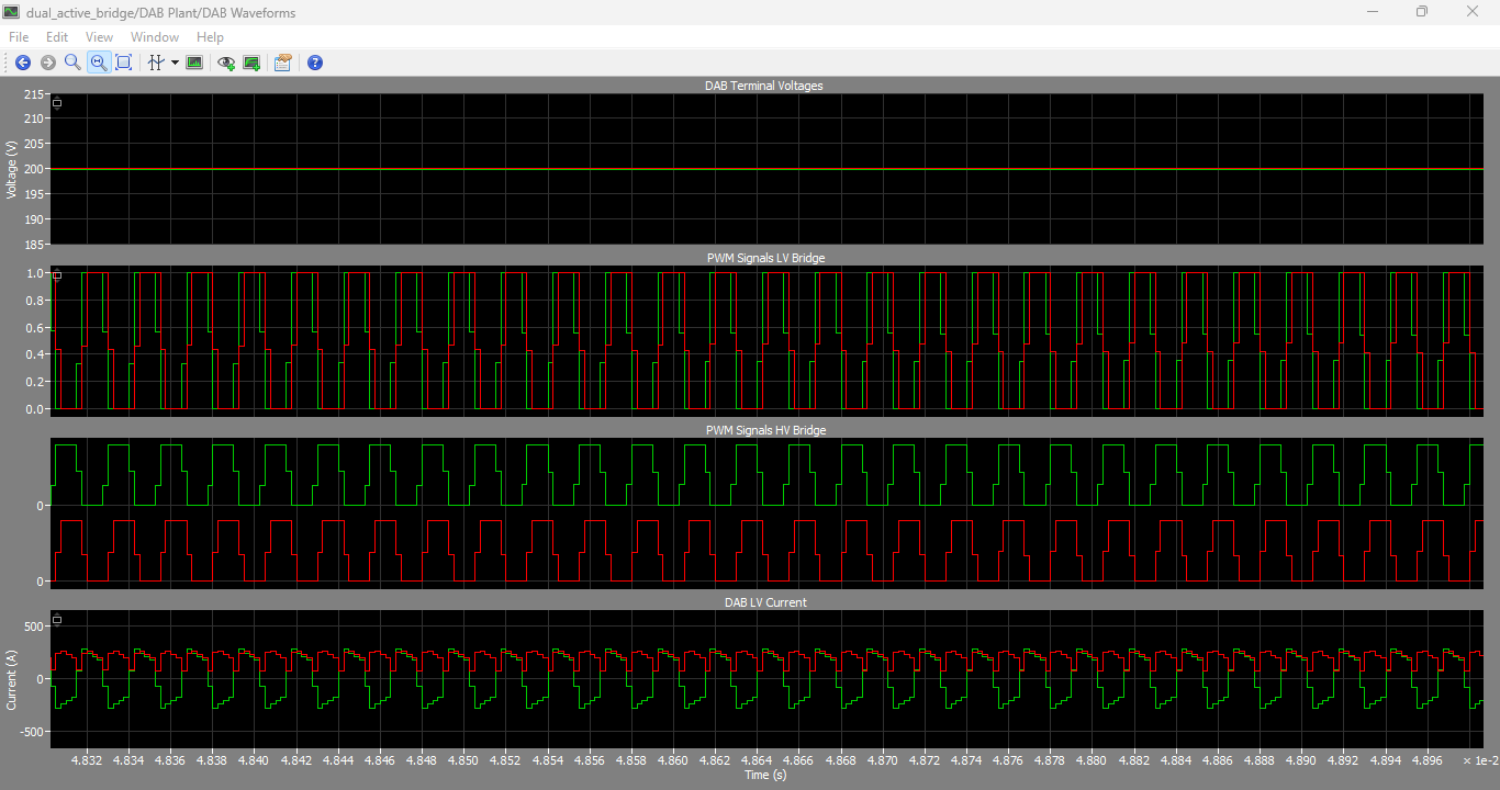
Figure 9: DAB terminal voltages and current waveforms
Figure 9 presents the converter terminal voltages and inductor current waveforms during DAB operation. The figure illustrates the battery-side voltage, high-voltage DC terminal voltage, leakage inductance voltage, and inductor current response.
The high-voltage and low-voltage terminal voltages remain stable throughout converter operation, indicating proper regulation of the power transfer process. The leakage inductance voltage waveform shows the effect of phase-shift modulation on energy transfer between the two bridges.
The inductor current waveform demonstrates smooth bidirectional power flow with controlled ripple components. The current waveform closely follows the expected phase-shift modulation behavior, validating the correctness of the developed DAB mathematical model and switching strategy.
XVI. Reference Current Tracking Performance
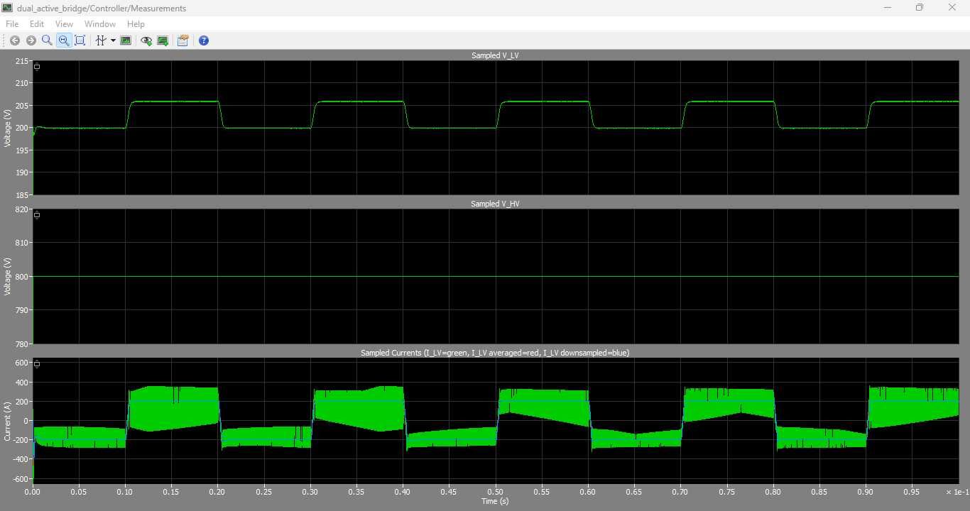
Figure 10: Reference current step response with feedforward enabled and disabled
You can download the Project files here: Download files now. (You must be logged in).
Figure 10 illustrates the closed-loop current tracking performance of the developed controller under varying reference conditions.
The simulation results show that the PI controller accurately tracks the commanded current reference during both charging and discharging operation. When feedforward control is enabled, the converter exhibits significantly faster dynamic response and reduced settling time compared to the conventional PI-only controller.
The phase-shift angle generated by the controller rapidly adjusts according to the required power transfer level. The feedforward controller effectively predicts the required operating point, reducing the burden on the PI regulator and improving transient performance.
The system achieves the designed 400 Hz closed-loop bandwidth while maintaining stable operation under rapid current transitions.
XVII. Switching Logic and PWM Analysis
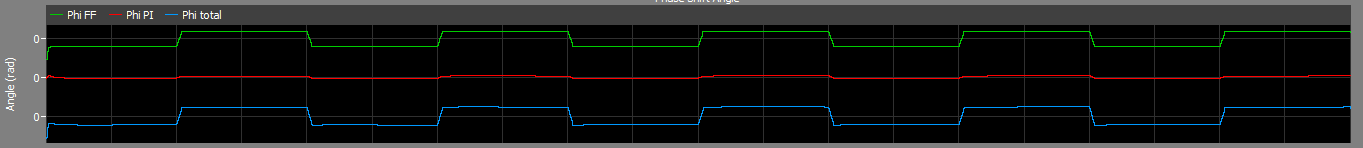
Figure 11: PWM switching logic and phase-shift signals
Figure 11 presents the PWM switching signals generated for the DAB full-bridge converters along with the corresponding phase-shift angle waveforms.
The switching signals demonstrate proper 180-degree phase displacement within each full bridge and variable phase displacement between the two bridges. This confirms the successful implementation of phase-shift modulation in the developed controller.
The phase-shift waveform varies dynamically according to the required current reference. Positive and negative phase-shift angles enable bidirectional power transfer between the DC source and battery system.
The PWM generation subsystem accurately synchronizes switching pulses while maintaining constant switching frequency operation.
XVIII. Real-Time Experimental Validation
The developed converter model was successfully deployed onto two PLECS RT Boxes for real-time validation.
The controller subsystem executes with a 2.5 µs sampling period while the plant subsystem operates using the same discretization step size. The controller execution time is approximately 1.2 µs while the plant execution time is approximately 2.3 µs.
Real-time operation confirms:
- Stable closed-loop control
- Accurate current tracking
- Reliable PWM generation
- Effective oversampling implementation
- Realistic converter behavior
The RT Box implementation demonstrates that the proposed model is suitable for hardware-in-the-loop testing and rapid controller prototyping for high-power battery charging applications.
XIX. Discussion
The developed DAB converter demonstrates several important advantages for battery charging applications.
First, the phase-shift modulation technique enables smooth bidirectional power transfer without requiring complex duty-cycle modulation strategies. This simplifies controller implementation while maintaining high efficiency.
Second, the oversampling and Moving Average Filter approach significantly improves current measurement quality. Since DAB converters inherently produce high-frequency current ripple, accurate current measurement becomes essential for stable control operation.
Third, the feedforward controller improves transient response by providing an initial estimate of the required phase-shift angle. This reduces controller settling time and improves dynamic performance.
Finally, the real-time implementation using RT Boxes enables rapid validation of converter behavior before physical hardware development. This significantly reduces development time and hardware testing risks.
The developed model can be extended further for:
- Electric vehicle charging systems
- Renewable energy integration
- Medium-voltage DC grids
- Aircraft electrical systems
- Smart battery management systems
XX. Conclusion
This paper presented the complete development and real-time implementation of a Dual Active Bridge DC/DC converter for battery charging applications using PLECS and PLECS RT Box.
The developed system includes detailed power-stage modeling, PI current control, feedforward compensation, oversampling implementation, and Moving Average Filtering techniques. Mathematical modeling and controller design procedures were presented in detail.
Simulation and real-time experimental results verified:
- Accurate current regulation
- Stable converter operation
- Fast transient response
- Effective bidirectional power transfer
- Successful hardware-in-the-loop implementation
The developed converter achieved stable operation at 50 kW power transfer capability using 40 kHz switching frequency and 2.5 µs discretization step size.
The proposed approach provides an efficient and reliable framework for developing advanced battery charging converters and real-time power electronics control systems.
References
- D. Freijedo, E. Rodriguez, and D. Dujic, “Stable and Passive High-Power Dual Active Bridge Converters Interfacing MVDC Grids,” IEEE Transactions on Industrial Electronics, vol. 65, no. 12, pp. 9561–9570, Dec. 2018.
- W. Erickson and D. Maksimovic, Fundamentals of Power Electronics, 2nd ed. Springer, 2001.
- Maksimovic and R. Zane, “Small-signal discrete-time modeling of digitally controlled PWM converters,” IEEE Transactions on Power Electronics, vol. 22, no. 6, pp. 2552–2556, Nov. 2007.
- Allmeling and N. Felderer, “Sub-cycle average models with integrated diodes for real-time simulation of power converters,” in IEEE Southern Power Electronics Conference (SPEC), 2017.
- Plexim GmbH, “PLECS User Manual and RT Box Documentation,” Zurich, Switzerland, 2023.
- Ogata, Modern Control Engineering, 5th ed. Prentice Hall, 2010.
- Mohan, T. Undeland, and W. Robbins, Power Electronics: Converters, Applications, and Design, 3rd ed. Wiley, 2003.
- G. Kassakian, M. F. Schlecht, and G. C. Verghese, Principles of Power Electronics. Addison-Wesley, 1991.
- Akagi, E. H. Watanabe, and M. Aredes, Instantaneous Power Theory and Applications to Power Conditioning. Wiley-IEEE Press, 2017.
You can download the Project files here: Download files now. (You must be logged in).


Responses