

Rankine Cycle Calculator: T-s Diagram, Reheat and Exit Quality
Calculate steam Rankine cycle efficiency, reheat, open feedwater heating and turbine exit quality using IAPWS-95 water properties, with a T-s diagram and animated plant.

This Rankine cycle calculator connects steam-table calculations to a complete T-s diagram and a moving plant drawing. Use it for thermodynamics coursework, checking a worked example, or comparing simple steam power cycles before a detailed plant study. It reports thermal efficiency, net specific work, back work ratio, heat rate, turbine exit quality, and the main steam flow needed for a chosen net power.
Start with boiler pressure, condenser pressure, and the turbine inlet temperature. You can instead select saturated vapor at the boiler outlet. Set both isentropic efficiencies to 1 for an ideal Rankine cycle; use lower values to include irreversible pumps and turbine stages. Water properties come from CoolProp's Water model using IAPWS-95, including the compressed liquid after each pump. Pressures are absolute.
Enable reheat to add an intermediate pressure and a second steam temperature. A reheat Rankine cycle usually delivers drier exhaust, while its efficiency also depends on the chosen pressure and heat input. Enable the open feedwater heater to study a regenerative Rankine cycle. The extraction fraction is calculated from its mixing balance, rather than entered independently. Extraction may occur above, below, or at the reheat pressure; at equal pressures, steam is extracted before reheating.
The bold cycle lies over the computed saturation dome and dashed pressure isolines. Temperature is plotted in kelvin so the shaded constant-pressure areas have a thermodynamic meaning. Heat areas refer to each stream; the reported heat and work are weighted by its fraction of the main boiler flow. Dashed purple connections identify the open heater's mixing streams and are guides between inlet and outlet states. Drag the boiler outlet point to change its pressure and temperature. The state table links each number to its physical location and steam properties.
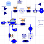
Press play to follow the working fluid through the boiler, turbine, condenser, pumps, and optional heater. Pipe colors use the calculated water temperatures; particle motion illustrates flow direction and branching, rather than residence time. The process-sample input refines the diagram and its heat-area integration without changing the thermodynamic state solution.
This steam cycle efficiency calculator models the working-fluid cycle, not fuel-to-electric plant efficiency. It excludes combustion losses, generator and mechanical losses, cooling-tower behavior, auxiliaries, pressure drops, heat leakage, closed feedwater heaters, multiple reheats, and transient operation. Exhaust quality is an equilibrium mass fraction; a single-phase exhaust is marked with −1 because quality is undefined there. Manufacturer turbine moisture limits, blade erosion, steam chemistry, and equipment sizing require separate assessment.
How it is calculated
Water properties are evaluated with fluid("Water", …), CoolProp 8.0.0, IAPWS-95. Each condenser outlet is saturated liquid; the open-heater outlet is saturated liquid at extraction pressure. For each adiabatic machine, find . A turbine gives ; a pump gives .
The heater balance is , hence . All energy results use one kg entering the boiler. Turbine work is summed stage by stage with the remaining mass fraction; the condensate pump and condenser carry , while the boiler feed pump carries one. Extraction before reheat also reduces the reheater flow. Net work is turbine work minus pump work, , and . Heat rate is kJ/kWh.
The dome is sampled at 180 temperatures clustered near the critical point. Cycle isobars include exact saturated liquid and vapor joins. The checks compare five published ideal, real, reheat, and regenerative examples, plus mass, energy, entropy, scaling, and heat-area convergence.
Assumptions
Steady operation; pure water; negligible kinetic and potential energy changes; adiabatic pumps, turbines, and mixing chamber. No component pressure drops. The same specified turbine efficiency applies separately to each expansion interval delimited by extraction, reheat, and the condenser. The pump efficiency applies to both pumps. The ideal-machine comparison preserves topology, pressures, and inlet temperatures but recalculates extraction with efficiencies of 1.
State 1 is the condenser outlet, 2 the first pump outlet, 3 the open-heater outlet, 4 the boiler feed pump outlet, and 5 the boiler outlet. Without regeneration, states 3–4 are bypassed and omitted. Later states follow the actual expansion and reheating sequence; the table names each location.
Where it applies
Subcritical boiler pressure 0.1–22 MPa; condenser pressure 1–100 kPa; superheat and reheat up to 700 °C. All pressures are absolute. Inlet steam must be saturated vapor or superheated; reheat must add heat. Inputs that produce an impossible pressure ordering, nonpositive net work, or an infeasible extraction fraction are rejected.
Exit quality is CoolProp's equilibrium vapor mass fraction in the two-phase region. The value −1 denotes a single-phase state; it is not a negative physical quality. The 90% quality (10% moisture) advisory is an educational comparison point, not an equipment acceptance criterion.
For real machines, intermediate T-s paths use the inlet-referenced stage efficiency at each sampled pressure; an overall isentropic efficiency does not uniquely determine a measured internal path. Purple heater connections are mixing guides, not reversible heat-transfer paths. Shaded isobar areas are per kg of the local stream, while outputs and heat-area checks include the relevant mass fractions. The enclosed real-cycle area is not asserted to equal net work.
The plant is a schematic cutaway, with temperatures mapped from calculated states and isobar samples; it is not a geometric design or a transient flow simulation. Animation speeds illustrate flow and branching only. Sampling controls diagram and quadrature resolution, not the exact property flashes used for state values. No constant-property approximation or interpolated steam table is used.
References
- Çengel, Y. A. & Boles, M. A., Thermodynamics: An Engineering Approach, 6th ed. (2008), Chapter 10, Example 10-1. Open worked case: Haq, BUET ME203 (2017), PDF p.2, slides 6 and 8: https://zahurul.buet.ac.bd/ME203/ME203_VapourPowerCycle.pdf
- Moran, M. J., Shapiro, H. N., Boettner, D. D. & Bailey, M. B., Fundamentals of Engineering Thermodynamics, 7th ed. (2011), Examples 8.3–8.5, pp.449–456. Independent IF97 calculations by Cheng Maohua: https://github.com/thermalogic/PyRankine/tree/master/notebook
- Wagner, W. & Pruß, A. (2002), The IAPWS Formulation 1995 for the Thermodynamic Properties of Ordinary Water Substance for General and Scientific Use. DOI: 10.1063/1.1461829. CoolProp Water documentation: https://coolprop.org/fluid_properties/fluids/Water.html
- Bell, I. H. et al. (2014), Pure and Pseudo-pure Fluid Thermophysical Property Evaluation and the Open-Source Thermophysical Property Library CoolProp. DOI: 10.1021/ie4033999.
Inputs
| Input | Symbol | Unit | Default |
|---|---|---|---|
| Boiler pressure | p_b | MPa | 15 |
| Boiler outlet | inlet | Superheated steam | |
| Turbine inlet temperature | T_b | °C | 600 |
| Condenser pressure | p_c | kPa | 10 |
| Turbine isentropic efficiency Applied separately between reheat, extraction, and exhaust pressures. | eta_t | 0.88 | |
| Pump isentropic efficiency | eta_p | 0.85 | |
| Net cycle power | P_net | MW | 100 |
| Enable reheat | reheat | true | |
| Reheat pressure | p_r | MPa | 3 |
| Reheat outlet temperature | T_r | °C | 600 |
| Enable open feedwater heater | regen | true | |
| Extraction / heater pressure Extraction may be before or after reheat; mixing occurs at this pressure. | p_e | MPa | 0.7 |
| Process samples per segment | N_path | 70 | |
| Flow animation time | t | s | 2.5 |
Results
With the default inputs above, the calc gives:
| Result | Value |
|---|---|
| Thermal efficiency (%) | 43.31 |
| Net work per kg main steam | 1,478.44 kJ/kg |
| Turbine exit quality (−1: single phase) | 0.9691 |
| Turbine exhaust phase | Wet steam |
| Main steam flow | 67.64 kg/s |
| Cycle heat rate | 8,312.2 kJ/kWh |
| Back work ratio (%) | 1.29 |
| Extraction fraction (%) | 16.52 |
| Extraction flow | 11.17 kg/s |
| Heat input per kg main steam | 3,413.63 kJ/kg |
| Heat rejected per kg main steam | 1,935.19 kJ/kg |
| External heat supply | 230.89 MW |
| Condenser heat load | 130.89 MW |
| Ideal-machine efficiency (%) | 47.67 |
Checked against sources
Each case below was calculated by this calc and agrees with the value from its source (within the tolerance where one is shown).
Çengel 10.1: ideal simple cycle
Source: Çengel & Boles, Thermodynamics: An Engineering Approach, 6th ed., Example 10-1, as worked by Dr. Md. Zahurul Haq, BUET ME203 (2017), PDF p.2, slide 6. Exact IAPWS-95 pump replaces the source's incompressible approximation.
Inputs: Boiler pressure = 3 MPa; Turbine inlet temperature = 350 °C; Condenser pressure = 75 kPa; Enable reheat = no; Enable open feedwater heater = no; Turbine isentropic efficiency = 1; Pump isentropic efficiency = 1; the others as above.
| Result | Source | This calc |
|---|---|---|
| Thermal efficiency | 0.26 ± 5 × 10⁻⁴ | 0.2602 |
| Net work per kg main steam | 710 ± 1.5 kJ/kg | 710 kJ/kg |
| Heat input per kg main steam | 2,729 kJ/kg | 2,729 kJ/kg |
BUET: 95% pump and turbine
Source: Haq, BUET ME203 (2017), PDF p.2, slide 8. The reported qin=2727.2 kJ/kg is inconsistent with its own 3.19 kJ/kg pump work and the preceding ideal case: qin should decrease by only about 0.16 kJ/kg. Compare the correct efficiency and machine works; retain exact property physics. Its wt=676.97 kJ/kg also differs from 0.95 times its preceding 713.0 kJ/kg ideal work (677.35); allow 0.6 kJ/kg for this rounding/inconsistency.
Inputs: Boiler pressure = 3 MPa; Turbine inlet temperature = 350 °C; Condenser pressure = 75 kPa; Enable reheat = no; Enable open feedwater heater = no; Turbine isentropic efficiency = 0.95; Pump isentropic efficiency = 0.95; the others as above.
| Result | Source | This calc |
|---|---|---|
| Thermal efficiency | 0.2471 ± 8 × 10⁻⁴ | 0.2471 |
| Mass-weighted turbine work | 677 kJ/kg | 677.4 kJ/kg |
| Mass-weighted pump input | 3.19 ± 0.015 kJ/kg | 3.192 kJ/kg |
Moran 8.3: ideal reheat
Source: Moran, Shapiro et al., Fundamentals of Engineering Thermodynamics, 7th ed. (2011), Example 8.3 pp.449–451. Independent IF97 implementation by Cheng Maohua, PyRankine notebook RankineCycle83-84.ipynb (s2). Expected values are its published outputs, not this calculator. Notebook's Qout result unit 'kg/h' is a typographical error; energy rate is MW.
Inputs: Boiler pressure = 8 MPa; Turbine inlet temperature = 480 °C; Condenser pressure = 8 kPa; Reheat pressure = 0.7 MPa; Reheat outlet temperature = 440 °C; Enable open feedwater heater = no; Turbine isentropic efficiency = 1; Pump isentropic efficiency = 1; the others as above.
| Result | Source | This calc |
|---|---|---|
| Thermal efficiency | 0.4033 ± 6 × 10⁻⁴ | 0.4033 |
| Main steam flow | 65.622 ± 0.15 kg/s | 65.618 kg/s |
| Condenser heat load | 148 ± 0.5 MW | 148 MW |
Moran 8.4: irreversible reheat
Source: Moran et al., Fundamentals of Engineering Thermodynamics, 7th ed. (2011), Example 8.4 p.451. Independently published IF97 output: Cheng, PyRankine, RankineCycle83-84.ipynb (s2).
Inputs: Boiler pressure = 8 MPa; Turbine inlet temperature = 480 °C; Condenser pressure = 8 kPa; Reheat pressure = 0.7 MPa; Reheat outlet temperature = 440 °C; Enable open feedwater heater = no; Turbine isentropic efficiency = 0.85; Pump isentropic efficiency = 1; the others as above.
| Result | Source | This calc |
|---|---|---|
| Thermal efficiency | 0.3509 ± 6 × 10⁻⁴ | 0.3509 |
Moran 8.5: open feedwater heater
Source: Moran et al., Fundamentals of Engineering Thermodynamics, 7th ed. (2011), Example 8.5 p.456. Independent IF97 implementation by Cheng, PyRankine RankineCycle85.ipynb (s3). Its displayed pump-work equation has a stray minus; the published numerical result uses positive pump input, as here.
Inputs: Boiler pressure = 8 MPa; Turbine inlet temperature = 480 °C; Condenser pressure = 8 kPa; Enable reheat = no; Turbine isentropic efficiency = 0.85; Pump isentropic efficiency = 1; the others as above.
| Result | Source | This calc |
|---|---|---|
| Thermal efficiency | 0.3691 ± 6 × 10⁻⁴ | 0.3691 |
| Extraction mass fraction | 0.1965 ± 5 × 10⁻⁴ | 0.1965 |
| Main steam flow | 102.4 ± 0.25 kg/s | 102.4 kg/s |



Responses