

Model Rocket Flight Simulator & Stability Calculator
Simulate model rocket altitude, ejection timing and parachute recovery. Check Barrowman stability and animate a flight using your own thrust points or idealized motor profiles.

Use this model rocket altitude calculator to explore how thrust, mass, drag and recovery choices affect a small rocket flight. It is intended for students, educators and hobbyists making preliminary comparisons before a launch. The animated schematic shows powered ascent, coast, ejection and canopy descent, while separate plots show thrust, altitude, vertical velocity and parachute performance.
Start with the rocket's burnout mass, including its recovery equipment and empty motor casing. Add the motor's propellant mass to obtain launch mass. Choose an idealized boost-and-sustain profile or constant thrust, then enter total impulse and burn time. These profiles are mathematical examples, not identified commercial motors. No motor database is distributed.
For your own motor data, choose My time–thrust points. Transfer six representative interior samples from a RASP .eng file, keeping the ignition peak, sustained thrust and tail. Times are seconds and thrusts are newtons. The calculator adds the origin and a zero-thrust point at the specified burn time. Enter the propellant mass separately from the header. This viewer does not upload or parse .eng files, and six samples may not preserve a detailed curve: compare the plotted shape and integrated impulse against the original data before relying on it.
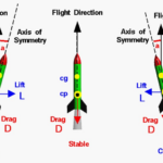
The rocket stability calculator uses a straight cylindrical body, a conical or tangent-ogive nose, and one set of three or four trapezoidal fins. All axial measurements start at the nose tip. Measure the loaded centre of gravity with the motor and recovery system installed. The tool calculates centre of pressure and estimates how CG moves as propellant disappears. A positive margin means CP is aft of CG; the one-caliber warning is a preliminary screening rule, not a guarantee of stable flight.
Select automatic deployment at predicted apogee to see the ideal ejection delay measured after burnout. Select a manual delay to examine early or late deployment. The free-flight apogee assumes no deployment, while the main apogee result includes the selected recovery timing. Actual motor delay tolerances, ignition behaviour and canopy inflation can change the outcome.
Use the parachute size calculator by entering a target descent speed and a canopy drag coefficient with its matching reference diameter. The diameter sweep illustrates the tradeoff between descent speed and time aloft. Wind drift covers only the period after deployment and assumes full wind advection.
The simulation is vertical, single-stage and constant-density. It rejects trajectories that hit the ground or reverse ascent before burnout; use a full-trajectory simulator for those motor profiles. It excludes weathercocking, launch-guide dynamics, terrain, turbulence, deployment loads, canopy inflation and structural failure. Body geometry does not determine airframe drag automatically. Keep predictions below about Mach 0.5 and 1 km altitude, compare with measured flights, and follow the launch site's rules and the motor manufacturer's instructions.
How it is calculated
Powered flight solves , and with adaptive Dormand–Prince integration. Here and : consumed propellant is proportional to cumulative impulse. Motor samples are linearly interpolated and trapezoidal integration gives total impulse. Integration restarts at every thrust-curve knot, carrying altitude, velocity and accumulated impulse across each boundary, so narrow thrust spikes cannot be skipped. The current-input impulse check compares numerical consumption with the exact integral of the linear segments; it blocks results above a relative discrepancy of 0.0001.
Liftoff is found from thrust minus the changing weight while the rocket remains on the pad. After that instant, pad holding is disabled. The first downward ground crossing is refined by bisection, the recorded trajectory ends at zero height, and further thrust cannot relaunch it. Ground impact during the burn and upward velocity reversing below −0.00001 m/s before burnout are rejected. The coast/apogee and ejection formulas apply only to a continuous ascent through burnout.
After burnout, constant mass and density permit exact quadratic-drag coast equations. For , the ideal delay is and free-flight apogee adds to burnout altitude. The zero-drag limit uses ballistic equations. Selected ejection may precede or follow free-flight apogee. The recovery solution switches instantly to canopy drag, handles residual upward motion and solves for touchdown without a fixed terminal-speed approximation.
Stability uses the simplified low-speed Barrowman nose-plus-fin method: nose normal-force factor 2; nose CP at two-thirds nose length for a cone or 0.466 for a tangent ogive; finite-span trapezoidal fin factor with fin–body interference. Component moments are divided by total normal-force factor to locate CP. Uniform body lift and transitions are omitted. NASA TM-2001-209983, attached pp. 12 and 16, gives the small-angle assumptions and quarter-chord basis. CG at burnout removes the propellant's mass moment. Static margin is ; its minimum occurs at one of the two burn endpoints under the assumed fixed propellant centroid.
Canopy sizing follows force balance , with . The recovery solution and wind drift are derived here from that balance and Newton's law.
Assumptions
- One stage; thrust remains vertical. No wind force or attitude dynamics during ascent.
- Constant air density, airframe drag coefficient and standard Earth gravity (9.80665 m/s²). A fixed 340.3 m/s sound speed is used only to screen the low-Mach range.
- Burnout mass includes the entire recovering vehicle and empty casing. Ejection-charge mass loss is omitted.
- Propellant consumption follows cumulative impulse, with a fixed propellant centroid. Airframe and spent motor mass distribution remain fixed.
- Three or four identical thin trapezoidal fins, a straight circular body and the selected ideal nose. The measured CG is independent of the drawing.
- The canopy opens completely and instantaneously. Its drag dominates airframe drag after deployment. Its reference diameter must match its quoted Cd; 0.75 is a flat-parasheet estimate.
- Wind drift equals wind speed multiplied by time after deployment; no ascent drift.
- The default and idealized motor shapes are original mathematical profiles, not manufacturer data.
Where it applies
For preliminary comparisons of slender, rigid, single-stage model rockets at small angle of attack, below roughly Mach 0.5 and 1 km altitude. The model requires continuous ascent after liftoff through burnout and deployment before ground impact. Any descent during the burn beyond a 0.00001 m/s numerical velocity tolerance is unsupported, even when later thrust restores upward motion. A downward ground crossing during the burn terminates the trajectory and blocks the flight predictions. The one-caliber margin and 20 m/s deployment-speed warning are screening cues, not certified limits.
Six manually entered interior samples can underresolve a complex .eng curve. Check integrated impulse and curve shape against your original. RASP header motor masses are not the airframe mass. No direct .eng uploader is available in this viewer.
No transonic aerodynamics, multiple fin sets, body transitions, boat tails, supersonic flight, weathercocking, rail-exit stability, canopy inflation, opening shock, structural loads or launch-site clearance prediction. A CP calculation alone cannot prove dynamic stability. Compare with a detailed flight simulator and measured flights before selecting a real motor delay. Follow local launch rules and the motor and recovery manufacturers' instructions.
References
- James S. Barrowman (1967), The Practical Calculation of the Aerodynamic Characteristics of Slender Finned Vehicles, NASA TM-2001-209983 (2001 republication), especially attached pp. 12, 16–20 and the body/tail treatment. https://ntrs.nasa.gov/citations/20010047838
- NASA Glenn Research Center, Rocket Stability. https://www1.grc.nasa.gov/beginners-guide-to-aeronautics/rocket-stability/
- NASA Glenn Research Center, Velocity During Recovery. https://www.grc.nasa.gov/www/k-12/VirtualAero/BottleRocket/airplane/rktvrecv.html
- Randy Culp, Rocket Equations: Alpha III worked constant-thrust example. https://www.rocketmime.com/rockets/rckt_eqn.html
- Randy Culp, Parachute Descent Calculations: Big Bertha and LOC V2 worked examples. https://www.rocketmime.com/rockets/descent.html
- ThrustCurve.org, RASP File Format: seconds/newtons, implicit origin, final zero thrust and header masses in kg. https://www.thrustcurve.org/info/raspformat.html
Inputs
| Input | Symbol | Unit | Default |
|---|---|---|---|
| Thrust profile Idealized profiles are mathematical shapes, not certified motor curves. No commercial motor database is supplied. | profile | Idealized boost and sustain | |
| Total impulse For the two idealized profiles; custom points determine their own impulse. | impulse | N*s | 9 |
| Motor burn time For custom data: time of the final zero-thrust sample. Idealized constant thrust cuts off abruptly at this time. | t_b | s | 1.6 |
| Burnout mass including empty motor Weigh the airframe, recovery system and spent motor together. RASP loaded motor mass is not the full rocket mass. | m_d | kg | 0.065 |
| Motor propellant mass RASP header field 5, in kg. The launch mass is burnout mass plus propellant. | m_p | kg | 0.012 |
| Air density at the field Kept constant throughout the flight; enter local air density for your field. | rho_air | kg/m^3 | 1.225 |
| Airframe drag coefficient Based on frontal body area. Geometry changes CP, but does not automatically change this empirical drag coefficient. | C_d | 0.6 | |
| Sample 1: time Transfer selected points from one motor in your own .eng data; include ignition peak and tail. The origin (0 s, 0 N) and final (burn time, 0 N) are added. | t1 | s | 0.03 |
| Sample 1: thrust | F1 | N | 10 |
| Sample 2: time Transfer selected points from one motor in your own .eng data; include ignition peak and tail. The origin (0 s, 0 N) and final (burn time, 0 N) are added. | t2 | s | 0.1 |
| Sample 2: thrust | F2 | N | 12 |
| Sample 3: time Transfer selected points from one motor in your own .eng data; include ignition peak and tail. The origin (0 s, 0 N) and final (burn time, 0 N) are added. | t3 | s | 0.25 |
| Sample 3: thrust | F3 | N | 6 |
| Sample 4: time Transfer selected points from one motor in your own .eng data; include ignition peak and tail. The origin (0 s, 0 N) and final (burn time, 0 N) are added. | t4 | s | 0.7 |
| Sample 4: thrust | F4 | N | 5 |
| Sample 5: time Transfer selected points from one motor in your own .eng data; include ignition peak and tail. The origin (0 s, 0 N) and final (burn time, 0 N) are added. | t5 | s | 1.2 |
| Sample 5: thrust | F5 | N | 4 |
| Sample 6: time Transfer selected points from one motor in your own .eng data; include ignition peak and tail. The origin (0 s, 0 N) and final (burn time, 0 N) are added. | t6 | s | 1.5 |
| Sample 6: thrust | F6 | N | 2 |
| Overall rocket length | L_r | mm | 500 |
| Body diameter | D_r | mm | 25 |
| Nose shape | nose | Cone | |
| Nose length | L_n | mm | 100 |
| Number of identical fins One set of three or four equally spaced, thin trapezoidal fins. | N_f | 3 | |
| Fin root chord | c_r | mm | 80 |
| Fin tip chord | c_t | mm | 40 |
| Fin span outside body | s_f | mm | 40 |
| Tip leading-edge sweep aft Axial distance aft from root leading edge to tip leading edge; not an angle. | sweep_f | mm | 30 |
| Fin root leading edge from nose tip | x_fin | mm | 400 |
| Loaded CG from nose tip Measure with motor and recovery system installed. | x_cg | mm | 345 |
| Propellant centroid from nose tip Assumed fixed during the burn; removing its mass predicts burnout CG. | x_prop | mm | 460 |
| Ejection timing | deploy | At predicted apogee | |
| Ejection delay after burnout Select a real motor delay only after allowing for its tolerance and verifying the flight. | delay | s | 5 |
| Parachute reference diameter Use the diameter associated with the quoted canopy Cd. For a flat parasheet this is usually its flat diameter. | D_ch | m | 0.45 |
| Parachute drag coefficient 0.75 is a simple flat parasheet estimate. Use tested manufacturer values with their matching reference diameter. | C_ch | 0.75 | |
| Target terminal descent speed Used to calculate the required parachute diameter. | v_target | m/s | 4 |
| Wind speed during canopy descent Drift estimate assumes the rocket immediately travels with this wind once deployed; ascent drift is omitted. | wind | m/s | 2 |
| Flight time ▶ Play ignition, coast, ejection and recovery. Rocket symbol and horizontal spacing are schematic. | t_play | s | 5 |
Results
With the default inputs above, the calc gives:
| Result | Value |
|---|---|
| Apogee with selected recovery | 316.5 m |
| Ideal ejection delay after burnout | 6.11 s |
| Minimum static margin · calibers | 1.85 |
| Barrowman CP from nose tip | 391.1 mm |
| Terminal canopy descent rate | 2.95 m/s |
| Parachute diameter for target speed | 0.332 m |
| Maximum ascent speed | 95.8 m/s |
| Upward speed at deployment | 0 m/s |
| Time to touchdown | 115.1 s |
| Wind drift after deployment | 215 m |
Checked against sources
Each case below was calculated by this calc and agrees with the value from its source (within the tolerance where one is shown).
Published Alpha III constant-thrust example
Source: Randy Culp, Rocket Equations, worked Alpha III example (constant effective mass 0.05398 kg, diameter 0.976 in, 6 N for 1.5 s, rho 1.2, Cd 0.75). Published heights 99.95 + 236.8 = 336.75 m. This reproduces the simplified example, not a licensed commercial thrust curve. Source rounds k and uses g=9.8; this tool retains exact area and g=9.80665. The source's final feet sum mixes rounded conversion factors, so SI heights are used. https://www.rocketmime.com/rockets/rckt_eqn.html
Inputs: Thrust profile = Idealized constant thrust; Motor burn time = 1.5 s; Burnout mass including empty motor = 0.05398 kg; Motor propellant mass = 0 kg; Body diameter = 24.79 mm; Air density at the field = 1.2 kg/m³; Airframe drag coefficient = 0.75; the others as above.
| Result | Source | This calc |
|---|---|---|
| Burnout upward velocity | 118 ± 0.15 m/s | 118 m/s |
| Burnout altitude | 99.95 ± 0.2 m | 99.927 m |
| Free-flight apogee above launch point | 336.8 ± 0.6 m | 336.5 m |
| Coast time from burnout to free-flight apogee | 5.915 ± 0.02 s | 5.912 s |
Published Big Bertha parasheet size
Source: Randy Culp, Parachute Descent Calculations, Model Rocket example: 0.0623 kg, rho=1.22 kg/m³, Cd=0.75, target 3 m/s gives D=0.435 m. The 0.0015 m tolerance includes the published rounding and gravity convention. https://www.rocketmime.com/rockets/descent.html
Inputs: Burnout mass including empty motor = 0.0623 kg; Air density at the field = 1.22 kg/m³; Target terminal descent speed = 3 m/s; the others as above.
| Result | Source | This calc |
|---|---|---|
| Parachute diameter for target speed | 0.435 ± 0.0015 m | 0.4347 m |
Published LOC V2 domed chute size
Source: Randy Culp, Parachute Descent Calculations, High-Power Rocket example: mass 3.6 kg, Cd 1.5, rho 1.22 kg/m³, target 5 m/s gives diameter 1.4 m. This is a recovery formula benchmark; flight geometry and motor are not the author's V2 flight. https://www.rocketmime.com/rockets/descent.html
Inputs: Burnout mass including empty motor = 3.6 kg; Air density at the field = 1.22 kg/m³; Parachute drag coefficient = 1.5; Target terminal descent speed = 5 m/s; Total impulse = 120 N·s; Motor burn time = 1.5 s; Motor propellant mass = 0.1 kg; the others as above.
| Result | Source | This calc |
|---|---|---|
| Parachute diameter for target speed | 1.4 ± 0.015 m | 1.402 m |
NASA rectangular-fin quarter-chord benchmark
Source: Barrowman NASA TM-2001-209983, attached p.16, establishes the subsonic quarter-chord location. For an unswept rectangular 80 mm fin whose leading edge is 400 mm from the nose tip, that published geometric rule independently places fin CP at 400 + 80/4 = 420 mm. This is a component identity benchmark, not measured whole-rocket CP.
Inputs: Fin tip chord = 80 mm; Tip leading-edge sweep aft = 0 mm; the others as above.
| Result | Source | This calc |
|---|---|---|
| Fin-set centre of pressure | 420 mm | 420 mm |
Reviewer regression: narrow thrust spike is resolved
Source: Independent reviewer supplied this custom curve and a separate integration resolving every linear thrust segment: integrated impulse 10.75 N·s, free-flight apogee 375.0 m. This is a numerical regression supplied in review, not a commercial motor curve or flight measurement. Other inputs remain the documented defaults.
Inputs: Thrust profile = My time–thrust points; Sample 2: time = 0.69 s; Sample 3: time = 0.7 s; Sample 4: time = 0.71 s; Sample 5: time = 1.4 s; Sample 1: thrust = 6 N; Sample 2: thrust = 6 N; Sample 3: thrust = 200 N; Sample 4: thrust = 6 N; Sample 5: thrust = 6 N; the others as above.
| Result | Source | This calc |
|---|---|---|
| Integrated motor impulse | 10.75 N·s | 10.75 N·s |
| Free-flight apogee above launch point | 375 ± 0.4 m | 375 m |
| Relative numerical impulse residual | 0 ± 1 × 10⁻⁴ | 1.652 × 10⁻¹⁶ |
Reviewer regression: impact ends powered trajectory
Source: Independent reviewer supplied this custom curve. The rocket lifts off, descends to ground during the long zero-thrust interval and must not relaunch. Ground is the launch datum, so a terminated physical trajectory has minimum height 0 m and is unsupported for the burnout/coast model. This is a boundary-condition regression, not a measured flight.
Inputs: Thrust profile = My time–thrust points; Motor burn time = 10 s; Sample 1: time = 0.05 s; Sample 2: time = 0.2 s; Sample 3: time = 0.3 s; Sample 4: time = 8.5 s; Sample 5: time = 8.6 s; Sample 6: time = 9.9 s; Sample 1: thrust = 5 N; Sample 2: thrust = 5 N; Sample 3: thrust = 0 N; Sample 4: thrust = 0 N; Sample 5: thrust = 5 N; Sample 6: thrust = 5 N; the others as above.
| Result | Source | This calc |
|---|---|---|
| Minimum altitude during powered flight | 0 m | 0 m |
| Powered flight is supported | 0 | 0 |
| Ground contact during the burn | 1 | 1 |
| Descent occurred before burnout | 1 | 1 |
Reviewer regression: reject apogee before burnout
Source: Independent reviewer supplied this curve and independently located its powered-flight peak near 226.3 m at 6.31 s, before the 10 s burnout. The burnout/coast ejection model must reject this trajectory rather than select a later, lower peak. Expected 0 means the continuous-ascent validity condition fails.
Inputs: Thrust profile = My time–thrust points; Motor burn time = 10 s; Sample 1: time = 0.05 s; Sample 2: time = 0.2 s; Sample 3: time = 0.3 s; Sample 4: time = 8.5 s; Sample 5: time = 8.6 s; Sample 6: time = 9.9 s; Sample 1: thrust = 30 N; Sample 2: thrust = 30 N; Sample 3: thrust = 0 N; Sample 4: thrust = 0 N; Sample 5: thrust = 2 N; the others as above.
| Result | Source | This calc |
|---|---|---|
| Powered flight is supported | 0 | 0 |
| Ground contact during the burn | 0 | 0 |
| Descent occurred before burnout | 1 | 1 |







Responses