

Hexapod Gait Stability: Slopes, Support Polygon and ZMP
Compare tripod, ripple and wave gaits on slopes and uneven footholds. Evaluate static margin, tipping energy, force-angle reserve and body-acceleration ZMP through a complete cycle.

Use this hexapod gait calculator to examine whether a prescribed walking pattern develops a tip-over tendency on a slope or uneven footholds. It is intended for robot designers, engineering students and builders comparing tripod, ripple and wave gaits. It follows the stance legs throughout a complete cycle rather than testing only a single attractive pose.
Start with the foot spacing, total mass and centre of mass (COM). The footprint has front, middle and rear legs on each side. Front and rear foot widths may differ from the middle width. Enter the stance stroke and cycle period to set the nominal forward speed. Choose a gait preset, override its duty factor to add contact overlap, or enter six touchdown phases for a custom sequence. The paired ripple preset has four stance feet; terminology differs between robotics platforms, so check the contact schedule against your controller.
Set terrain inclination and uphill azimuth to orient the slope in any direction relative to the robot. Forward is +x and left is +y. Each leg has an additional ground height measured normal to that reference plane. These six offsets describe the footholds used in the repeating cycle. They do not describe every obstacle between consecutive foot placements. Set them to zero for a single planar slope.
The play control moves through the gait while the full-cycle results remain available. Filled feet are in stance; open feet are swinging. The shaded boundary joins the outer stance contacts, and orange marks the edge with the least force-angle reserve. The horizontal view shows the static support polygon and shortest COM projection distance. The contact schedule shows when each leg supports the body.
Static stability margin measures distance to the support boundary. The gravitational energy barrier measures the potential energy needed to rotate the COM to a tipping position about a real three-dimensional edge. The force-angle measure also includes the prescribed body acceleration and net COM moment. Periodic sway generates consistent COM displacement and acceleration; the prescribed-acceleration option instead evaluates a fixed acceleration throughout the contact sequence.
Read the minimum margins before inspecting the animated pose. A negative force-angle reserve indicates an outward tipping tendency in the assumed contact model. A positive reserve describes the specified loading, not the ability to recover after an impact or a missed foothold. The ZMP is calculated on the inclined reference plane; on noncoplanar terrain it is a useful comparison, while the three-dimensional edge calculation supplies the tip-over assessment.
This tool does not solve joint torques, leg reach, friction cones, contact compliance, touchdown impacts or a feedback controller. Those checks remain necessary before translating a promising gait into robot operation.
How it is calculated
For each leg, local phase is and stance is . Presets use duty factors ½, ⅔ and ⅚. The ripple preset cycles three opposite-side pairs; custom phases allow other conventions. Feet move backwards by the stance stroke at constant speed relative to uniform body translation. Swing returns them with a sinusoidal-squared lift.
An orthonormal terrain frame rotates the footprint by inclination and uphill azimuth. Each foothold retains its own normal offset. The horizontal convex hull of the stance contacts defines McGhee–Frank's support polygon. Static margin is the shortest horizontal distance from the vertical COM projection to its boundary, positive inside and negative outside. Distances outside corners are measured to the boundary segments.
For each actual 3D hull edge, let be its unit direction and . The following height expression is derived from a circle about an inclined axis. During rotation about that edge the largest attainable COM height increase is . The Messuri–Klein gravitational barrier is the minimum over edges. An edge already carrying an outward gravity moment has zero remaining barrier.
Use and the entered net COM moment . Following Papadopoulos and Rey (1996), equations (5), (9)–(15), the edge force is . The signed angle between and is obtained with atan2; counterclockwise hull ordering makes inward reserve positive. The original measure is , with angles in radians (dimensionless in SI), so its displayed unit is force. Periodic COM sway uses one harmonic per axis, with acceleration equal to minus squared frequency times displacement.
For the reference plane through the origin with unit normal , . Its signed margin uses the orthogonal projections of the stance feet onto that plane. The tangential moment residual independently checks the zero-moment condition.
Assumptions
The body and payload are represented by total mass and a prescribed COM. The body frame follows the reference slope, with no solved attitude motion. All scheduled stance contacts are maintained without slipping; legs can reach their specified footholds. Per-leg heights repeat each cycle.
Foothold offsets, prescribed accelerations and net COM moments use terrain axes: +x forward, +y left and +z normal away from the reference plane. Positive foothold height is away from that plane. Moments follow the right-hand rule and equal applied moments minus the rate of angular momentum at the COM, including limb effects when known. Prescribed acceleration is held fixed as contact phases vary; it is a frozen loading case rather than an integrated accelerating trajectory. Standard gravity is 9.80665 m/s².
Where it applies
Cycle extrema use 1080 uniform intervals plus touchdown and liftoff and their one-sided limits at 10⁻⁸ cycle. The same 3D equations are evaluated at every sample; the plotted lines do not smooth over contact changes. A narrow interior extremum may lie slightly below the sampled minimum, so inspect and refine the phase when reserve approaches zero. Hulls are reused only while the same contacts remain active; their common stance translation leaves hull ordering unchanged. The energy margin includes gravity only and excludes kinetic energy and impact work. On noncoplanar footholds there is no unique physical support-plane ZMP: the reference-plane value and its margin are diagnostics, not a contact-wrench feasibility test. The original 1996 force-angle candidate-edge construction uses the horizontal contact hull with actual 3D edge endpoints. Positive reserve does not prove feasible friction forces, sufficient actuator torque, attainable leg reach, disturbance recovery or successful touchdown. Local surface normals, soil settlement, foot area, compliant load sharing and controller dynamics are not solved.
References
- McGhee, R. B. and Frank, A. A. (1968), On the stability properties of quadruped creeping gaits, Mathematical Biosciences 3, 331–351. https://doi.org/10.1016/0025-5564(68)90090-4
- Messuri, D. A. and Klein, C. A. (1985), Automatic body regulation for maintaining stability of a legged vehicle during rough-terrain locomotion, IEEE Journal of Robotics and Automation RA-1(3), 132–141. https://doi.org/10.1109/JRA.1985.1087012
- Papadopoulos, E. G. and Rey, D. A. (1996), A new measure of tipover stability margin for mobile manipulators, ICRA, 3111–3116, equations (5), (9)–(15), attached PDF pp. 3–4. https://doi.org/10.1109/ROBOT.1996.509185 ; author copy https://nereus.mech.ntua.gr/pdf_ps/ICRA96.pdf
- Vukobratović, M. and Borovac, B. (2004), Zero-moment point — thirty five years of its life, International Journal of Humanoid Robotics 1(1), 157–173. https://doi.org/10.1142/S0219843604000083
- Bai, L., Hu, H., Chen, X., Sun, Y., Ma, C. and Zhong, Y. (2019), CPG-Based Gait Generation of the Curved-Leg Hexapod Robot with Smooth Gait Transition, Sensors 19, 3705, Table 1 and Tables 2–3, attached PDF pp. 3 and 6; gait counts p. 5. https://doi.org/10.3390/s19173705
Inputs
| Input | Symbol | Unit | Default |
|---|---|---|---|
| Gait pattern | gait | Tripod | |
| Set duty factor | override_duty | false | |
| Stance duty factor Fraction of the cycle in contact; presets use ½, ⅔ and ⅚. | duty_set | 0.6 | |
| Cycle period | period | s | 1.8 |
| Cycle phase Play one repeating cycle; zero is left-front touchdown. | phase | 0.32 | |
| LF touchdown phase Fraction of one cycle. | ph_LF | 0 | |
| LM touchdown phase Fraction of one cycle. | ph_LM | 0.5 | |
| LR touchdown phase Fraction of one cycle. | ph_LR | 0 | |
| RF touchdown phase Fraction of one cycle. | ph_RF | 0.5 | |
| RM touchdown phase Fraction of one cycle. | ph_RM | 0 | |
| RR touchdown phase Fraction of one cycle. | ph_RR | 0.5 | |
| Front–rear foot spacing | span | m | 0.6 |
| Front and rear foot width | width_end | m | 0.46 |
| Middle foot width | width_mid | m | 0.56 |
| Stance stroke Foot travel relative to uniform body translation during stance. | stroke | m | 0.12 |
| Swing foot lift | lift | m | 0.05 |
| Total mass | mass | kg | 12 |
| Mean COM height Measured normal to the reference terrain plane. | height | m | 0.22 |
| COM forward offset | offset_x | m | 0.015 |
| COM left offset | offset_y | m | 0 |
| Terrain inclination | incline | deg | 12 |
| Uphill azimuth Zero is forward; +90° is toward the left legs. | uphill | deg | 30 |
| LF ground height | ground_LF | m | 0.01 |
| LM ground height | ground_LM | m | 0 |
| LR ground height | ground_LR | m | 0 |
| RF ground height | ground_RF | m | 0 |
| RM ground height | ground_RM | m | 0.02 |
| RR ground height | ground_RR | m | -0.005 |
| Body acceleration model | motion | Periodic COM sway | |
| Fore–aft sway amplitude | sway_x | m | 0.008 |
| Lateral sway amplitude | sway_y | m | 0.012 |
| Normal sway amplitude | sway_z | m | 0.004 |
| Sway phase offset Fore–aft and normal use cosine; lateral uses sine. | sway_phase | deg | 20 |
| Forward COM acceleration | acc_x | m/s^2 | 0.4 |
| Left COM acceleration | acc_y | m/s^2 | 0.2 |
| Normal COM acceleration | acc_z | m/s^2 | 0 |
| Roll net COM moment | torque_x | N*m | 0 |
| Pitch net COM moment | torque_y | N*m | 0 |
| Yaw net COM moment | torque_z | N*m | 0 |
Results
With the default inputs above, the calc gives:
| Result | Value |
|---|---|
| Cycle tip-over assessment | Positive tip-over reserve |
| Minimum static margin | 65.076 mm |
| Minimum gravitational energy barrier | 1.057 J |
| Minimum force-angle reserve | 16.27 deg |
| Minimum 1996 force-angle measure, radian weighted | 33.188 N |
| Minimum reference-plane ZMP margin | 66.396 mm |
| Phase of minimum force-angle reserve | 0 |
| Minimum stance feet | 3 |
| Mean forward speed | 0.133 m/s |
| Current force-angle reserve | 27.45 deg |
| Current ZMP forward coordinate in terrain plane | -32.068 mm |
| Current ZMP left coordinate in terrain plane | -12.217 mm |
Checked against sources
Each case below was calculated by this calc and agrees with the value from its source (within the tolerance where one is shown).
Published tripod count and 140 mm side edge
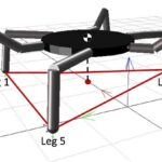
Source: Bai et al. (2019), DOI 10.3390/s19173705, Table 1 dimensions and Table 2 d15=140 mm, with Fig. 2(a) three stance legs. LF and LR correspond to paper legs 1 and 5. Zero stroke isolates the published support geometry. Their diagonal entries 93 mm do not follow from the listed 230 mm station spacing, 280/320 mm widths: the exact geometric distance is 97.349 mm; those inconsistent entries are not used as expected values.
Inputs: Terrain inclination = 0 deg; Stance stroke = 0 m; COM forward offset = 0 m; LF ground height = 0 m; RM ground height = 0 m; RR ground height = 0 m; Body acceleration model = Prescribed acceleration; Forward COM acceleration = 0 m/s²; Left COM acceleration = 0 m/s²; Front–rear foot spacing = 0.46 m; Front and rear foot width = 0.28 m; Middle foot width = 0.32 m; Cycle phase = 0.25; the others as above.
| Result | Source | This calc |
|---|---|---|
| Current stance feet | 3 | 3 |
| Minimum stance feet | 3 | 3 |
| Current signed edge-line static distances [3] | 0.14 m | 0.14 m |
Published wave count and pentagon edge distances
Source: Bai et al. (2019), DOI 10.3390/s19173705, Table 3: d46=159 mm (rounded to the nearest millimetre), d12=230 mm and d15=140 mm; Fig. 2(c) five stance feet. At phase zero LM is swinging; contact numbering is mapped LF=1, LM=3, LR=5, RF=2, RM=4, RR=6. The current support boundary includes these published edges.
Inputs: Terrain inclination = 0 deg; Stance stroke = 0 m; COM forward offset = 0 m; LF ground height = 0 m; RM ground height = 0 m; RR ground height = 0 m; Body acceleration model = Prescribed acceleration; Forward COM acceleration = 0 m/s²; Left COM acceleration = 0 m/s²; Gait pattern = Wave (one swing); Front–rear foot spacing = 0.46 m; Front and rear foot width = 0.28 m; Middle foot width = 0.32 m; Cycle phase = 0; the others as above.
| Result | Source | This calc |
|---|---|---|
| Current stance feet | 5 | 5 |
| Minimum stance feet | 5 | 5 |
| Current static margin | 0.14 m | 0.14 m |
| Current signed edge-line static distances [1] | 0.159 ± 5 × 10⁻⁴ m | 0.1594 m |
| Current signed edge-line static distances [3] | 0.23 m | 0.23 m |
Published four-stance paired gait
Source: Bai et al. (2019), DOI 10.3390/s19173705, section 2.2 / attached PDF p. 5: the quadruped or tetrapod gait has four stance feet and two swing feet. This tool calls the three-pair sequence ripple; the phase schedule is explicit.
Inputs: Terrain inclination = 0 deg; Stance stroke = 0 m; COM forward offset = 0 m; LF ground height = 0 m; RM ground height = 0 m; RR ground height = 0 m; Body acceleration model = Prescribed acceleration; Forward COM acceleration = 0 m/s²; Left COM acceleration = 0 m/s²; Gait pattern = Ripple (paired, four stance); the others as above.
| Result | Source | This calc |
|---|---|---|
| Current stance feet | 4 | 4 |
| Minimum stance feet | 4 | 4 |






Responses