

Duct Size Calculator and HVAC Fan Curve
Size a five-segment duct tree by equal friction, calculate fitting and balancing losses, and match the system to a blower curve. Supports round and rectangular ducts.

This duct size calculator sizes a small branching air-distribution system and checks whether a blower can deliver the requested airflows. It is intended for engineers, students and people comparing practical duct layouts. Unlike a single-segment ductulator, it follows a shared trunk, a direct outlet branch, and a subtrunk feeding two further outlets.
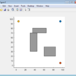
Start with the required airflow at outlets A, B and C. Enter each straight length and the sum of fitting loss coefficients for its segment. The schematic identifies the five segments. Choose round or rectangular ducts, an equal-friction target, and a rounding increment. Rectangular sizing uses a common width-to-height ratio; the selected size is the shorter internal side. The increment is a convenience for sizing, not a catalogue of available products. Check the resulting dimensions with your supplier.
For a cfm duct size calculation, type an airflow with its unit, such as 500 ft³/min, into an airflow field. Set “Schematic units” to metric for mm, L/s and Pa, or US for inches, cfm and conventional inches of water column. All drawing captions use that selection together. This drawing selector is separate from the viewer’s SI/US switch for input and result fields. Tables and chart axes state their units. One conventional inch of water equals 249.08891 Pa.
To assess existing ductwork, select “Check entered duct sizes” and enter the clear diameter or rectangular short side of every segment. The tool recalculates friction and actual velocity. Supply K-values referenced to each segment’s actual duct velocity, including junction, diffuser and discharge losses where applicable. Use manufacturer data or your own justified coefficients; no proprietary fitting database is embedded.
Enter three blower-curve points at one rated speed and air density. Identify whether the pressures are fan static or fan total pressure, and enter the actual fan outlet area. The static pressure calculator then converts between rating bases consistently. The chart shows the intersection of the blower and system curves. Interpolation stays within the entered flow range; missing intersections require more rated data or a different selection.
With balancing enabled, the calculator determines additional terminal damper losses needed for the requested outlet split. Those coefficients stay fixed while it solves the operating point. Disable balancing to see how unequal path resistances redistribute airflow. The airflow animation shows direction and relative tracer speed on a schematic layout.
This is a steady, low-speed rigid-duct model. Actual hydraulic Reynolds numbers must be at least 4000. Design ducts, operating ducts and the fan outlet must stay at or below 60 m/s. Enter the lowest expected absolute system pressure, including fan suction, rather than gauge pressure. The design and operating pressure-variation bounds must also stay within 10% of that pressure; they include total-pressure losses and the largest duct or fan outlet velocity pressure. Invalid cases withhold results. It does not determine ventilation requirements, acoustic performance, duct leakage, flexible-duct compression, fire protection, or structural construction. It is not an ACCA Manual D compliance calculation. Confirm fan stability, manufacturer speed limits, component pressure boundaries and the standard in force. Installation and commissioning belong to a qualified person.
How it is calculated
The tree conserves airflow at each junction. Equal-friction sizing solves a round diameter for each design flow, then rounds upward. For a rectangle, Huebscher equivalence is
The diameter and both sides use the same length unit. The selected rectangle is evaluated as an equivalent round duct for straight friction, while fitting losses use its actual area.
For every segment,
Flow validity uses the actual velocity and hydraulic diameter: , with for rectangles and for round ducts. Equivalent-round Reynolds numbers are retained only for the friction approximation. Viscosity entered in mm²/s is explicitly converted to m²/s.
Colebrook is iterated ten times. The solver uses 64/Re below 2300 and a transition blend to 4000 only to continue the resistance curves; design sizing requires turbulent flow.
Balancing adds nonnegative terminal K-values so all requested paths have equal loss. At other flows, those K-values remain fixed. The tree solver updates friction factors and parallel-path flow fractions until they converge; a pressure-residual condition verifies equilibrium. Bisection finds the fan–system intersection.
The three fan points use linear interpolation. Speed scales flow by the speed ratio and pressure by its square; density scales pressure proportionally. Fan total pressure equals fan static pressure plus fan outlet velocity pressure. Shared equipment loss scales with total flow squared. Air power is total pressure times airflow, before fan, drive and motor losses.
Compressibility screening follows the approximate pressure-drop guidance in ASHRAE Fundamentals (2017), Chapter 3, Compressible Conduit Flow. For each design/operating state, a conservative static-pressure variation bound is the total-pressure budget plus the largest duct or fan outlet velocity pressure:
The bound follows the static/total-pressure relation; it is intentionally more restrictive than checking total-pressure loss alone. The minimum absolute pressure is a user-supplied lower bound over the modeled circuit. The screen does not modify the constant-density solution.
Assumptions
- One shared trunk T feeds direct branch A and subtrunk S; S feeds terminal branches B and C. All terminals discharge to the same reference pressure. The model does not support arbitrary topology.
- Air is incompressible with uniform density and kinematic viscosity supplied by the user. Defaults represent ordinary room-temperature air. The entered minimum absolute pressure must be a valid lower bound throughout the modeled circuit, including fan suction; its 100 kPa default is a near-sea-level estimate.
- All ducts are rigid, internally clear, constant-section segments, with one common roughness and one cross-section family. Rectangular aspect ratios are limited to 1–4.
- Nonnegative fitting K-values refer to actual local segment velocity and are fixed with flow. Convert coefficients referenced to a different section using the square of the velocity ratio. Junction interaction, negative individual loss coefficients and fan system effects require separate engineering judgment.
- Terminal K includes the outlet kinetic-energy loss unless the selected diffuser data already includes it. Shared equipment loss includes only components outside the chosen rated fan boundary.
- Default lengths, K-values and three blower points are editable illustrative design inputs, not manufacturer or standards data. Replace them for an actual selection. The default 0.09 mm roughness follows ASHRAE's average rigid-duct friction chart.
- The drawing is schematic with symbolic tracer motion. Its Schematic units selector switches every drawing caption together between metric (mm, L/s, Pa) and US (in, cfm, conventional in. w.c.). This selector is independent of the viewer’s field-unit switch. Size rounding does not guarantee a commercially available size. Fan speed scaling does not assess motor power or permitted wheel speed.
Where it applies
Use for preliminary sizing and comparison of turbulent, low-speed air flow in rigid round or rectangular ducts. Error conditions reject design or operating Reynolds numbers below 4000, using actual duct velocity and hydraulic diameter. The equivalent-round Reynolds number is not the rectangular-flow validity criterion. The transition blend only continues the system curve numerically; it does not validate transitional flow.
Only use rated data from a stable decreasing portion of one blower curve. The tool requires an intersection within the entered range and reports convergence residuals. A three-point linear curve cannot resolve stall, surge, controls, or multiple operating points. The pressure margin at the requested flow is only meaningful within the rated range.
The requested-split pressure budget assumes the calculated balancing dampers are fitted. With balancing disabled, delivered outlet flows generally differ from the requests; use the delivered-flow table. The passive network is re-solved with fixed geometry as blower flow changes. The 95% delivery advisory and velocity threshold are review aids, not compliance criteria.
No ACCA Manual D text or ASHRAE fitting database is reproduced. Flexible duct compression, leakage, changing filter loading, stack and wind effects, acoustics, heat transfer, duct construction and code compliance are outside the model. Check against the standard in force and the actual fan installation category. Installation, balancing and commissioning belong to a qualified person.
The constant-density approximation has two independent screens. Every design and operating duct velocity, and the fan outlet velocity at both flows, must be at most 60 m/s. The pressure-variation bound at each flow must also be at most 10% of the entered minimum absolute system pressure. Both screens block results when exceeded; neither is a universal compressibility boundary.
Enter the lowest expected absolute static pressure anywhere in the modeled circuit, including fan suction, in the Minimum absolute system pressure field. Use site barometric pressure minus the largest expected suction; never enter gauge pressure. The default 100 kPa is a near-sea-level estimate, not a site measurement. Air density and viscosity must represent the same conditions.
ASHRAE Fundamentals (2017), Chapter 3, Compressible Conduit Flow, gives an approximate 10% initial-pressure-drop limit for incompressible conduit analysis. This tool conservatively compares the total-pressure budget plus the largest duct/fan outlet velocity pressure with 10% of the supplied minimum absolute static pressure. The added velocity-pressure allowance covers static-pressure changes caused by section velocity changes. This is an applicability screen, not a compressible-flow correction; use a compressible model outside it. NASA Glenn discusses the separate dependence on Mach number.
References
- ASHRAE Handbook—Fundamentals (2021), Chapter 21, Duct Design (public SI chapter), Darcy–Colebrook equations, Huebscher equivalence, Example 6 baseline results, and fan pressure definitions. https://handbook.ashrae.org/Handbooks/F21/SI/F21_Ch21/F21_Ch21_si.aspx
- Autodesk AutoCAD MEP (2019), About Duct Sizing Methods: distinction between round-equivalent friction velocity and actual fitting/acoustic velocity. https://help.autodesk.com/cloudhelp/2019/ENU/AutoCAD-MEP/files/GUID-0D61887B-31E6-483D-838E-43274CA944A8.htm
- William Howarth, AMCA inMotion (2020), Straightening Out Fan Curves: static/total pressure and the 300AF worked example. https://www.amca.org/educate/articles-and-technical-papers/amca-inmotion-articles/straightening-out-fan-curves.html
- Greenheck, Fan Fundamentals — Introduction to Fan Selection, PDF page 5 (printed 133), fan laws worked example. https://content.greenheck.com/public/DAMProd/Original/10002/FanFundamentals.pdf
- NIST SP 811 Appendix B.9: 1 ft³/min = 0.0004719474 m³/s; 1 conventional inch of water = 249.0889 Pa. https://www.nist.gov/pml/special-publication-811/nist-guide-si-appendix-b-conversion-factors/nist-guide-si-appendix-b9
- ASHRAE Handbook—Fundamentals (2017), Chapter 3, Fluid Flow: actual hydraulic Reynolds number and the Compressible Conduit Flow section's approximate 10% initial-pressure-drop applicability limit. https://handbook.ashrae.org/Handbooks/F17/SI/f17_ch03/f17_ch03_si.aspx
- NASA Glenn Research Center, Role of Mach Number in Compressible Flows (updated 2021): compressibility and density variation with flow speed. https://www.grc.nasa.gov/www/BGH/machrole.html
Inputs
| Input | Symbol | Unit | Default |
|---|---|---|---|
| Sizing mode The tree has five segments and three outlets. See the schematic for segment names. | sizing_mode | Size to equal friction | |
| Duct cross-section One cross-section family is applied to the whole tree. | shape | Round | |
| Rectangular width / height The entered or selected size is the short side; width equals aspect ratio times height. | aspect | 2 | |
| Target straight-duct friction Sizing uses Darcy–Colebrook. This is a design choice, not a prescribed Manual D friction rate. | fr_target | Pa/m | 0.8 |
| Size rounding increment Round diameter or rectangular short side is rounded up to this increment. Confirm supplier availability. | increment | mm | 25 |
| Balance outlets to design flows Adds calculated damper K to the three terminal branches. Off: predicts the unbalanced flow distribution. | balance | true | |
| Velocity review threshold An advisory threshold chosen by you; this is not an acoustic compliance limit. | v_limit | m/s | 8 |
| Outlet A design airflow Actual volumetric airflow at the entered air density. You may type a quantity such as 500 ft^3/min; it is converted to L/s. | q_A | L/s | 160 |
| Outlet B design airflow Actual volumetric airflow at the entered air density. You may type a quantity such as 500 ft^3/min; it is converted to L/s. | q_B | L/s | 120 |
| Outlet C design airflow Actual volumetric airflow at the entered air density. You may type a quantity such as 500 ft^3/min; it is converted to L/s. | q_C | L/s | 100 |
| Shared trunk T length Straight developed length; fittings are entered separately as K. | L_T | m | 8 |
| Shared trunk T total fitting K Sum of losses referenced to this segment's actual velocity. Terminal branches must include discharge/diffuser loss. Convert K from another reference area before entry. | K_T | 0.5 | |
| Shared trunk T entered size Round diameter or rectangular short side. Internal clear dimensions. | size_T | mm | 325 |
| Direct branch A length Straight developed length; fittings are entered separately as K. | L_A | m | 7 |
| Direct branch A total fitting K Sum of losses referenced to this segment's actual velocity. Terminal branches must include discharge/diffuser loss. Convert K from another reference area before entry. | K_A | 2 | |
| Direct branch A entered size Round diameter or rectangular short side. Internal clear dimensions. | size_A | mm | 250 |
| Subtrunk S to B + C length Straight developed length; fittings are entered separately as K. | L_S | m | 5 |
| Subtrunk S to B + C total fitting K Sum of losses referenced to this segment's actual velocity. Terminal branches must include discharge/diffuser loss. Convert K from another reference area before entry. | K_S | 0.4 | |
| Subtrunk S to B + C entered size Round diameter or rectangular short side. Internal clear dimensions. | size_S | mm | 275 |
| Terminal branch B length Straight developed length; fittings are entered separately as K. | L_B | m | 6 |
| Terminal branch B total fitting K Sum of losses referenced to this segment's actual velocity. Terminal branches must include discharge/diffuser loss. Convert K from another reference area before entry. | K_B | 2.5 | |
| Terminal branch B entered size Round diameter or rectangular short side. Internal clear dimensions. | size_B | mm | 225 |
| Terminal branch C length Straight developed length; fittings are entered separately as K. | L_C | m | 10 |
| Terminal branch C total fitting K Sum of losses referenced to this segment's actual velocity. Terminal branches must include discharge/diffuser loss. Convert K from another reference area before entry. | K_C | 3 | |
| Terminal branch C entered size Round diameter or rectangular short side. Internal clear dimensions. | size_C | mm | 200 |
| Shared equipment loss at design flow Return path, filter, coil or other shared losses outside the rated fan boundary. Scales with flow squared. Do not count a component twice. One conventional inch of water equals 249.08891 Pa. | p_aux | Pa | 70 |
| Air density Use site air properties; default represents dry air near 20 °C at sea level. | rho_air | kg/m^3 | 1.204 |
| Minimum absolute system pressure Lowest expected absolute static pressure anywhere in the modeled circuit, including fan suction. Use site barometric pressure minus the largest expected suction; this is not gauge pressure. Default 100 kPa is a near-sea-level estimate. | p_abs_min | kPa | 100 |
| Air kinematic viscosity Use a property source for site temperature and pressure. Default 15 mm²/s equals 1.5 × 10^-5 m²/s; conversion is explicit in the calculation. | nu_air | mm^2/s | 15 |
| Absolute roughness Default follows ASHRAE's average rigid duct friction chart. Not a flexible-duct compression model. | eps | mm | 0.09 |
| Curve pressure rating Enter three manufacturer points at one speed and density, on a decreasing stable portion. Defaults are illustrative engineering inputs, not a product rating. | fan_basis | Fan static pressure | |
| Curve point 1 airflow Points must increase in airflow. The calculator does not extrapolate outside them. You may type a quantity such as 500 ft^3/min; it is converted to L/s. | fan_q0 | L/s | 0 |
| Curve point 1 pressure Pressure on the selected rating basis, at the curve density and reference speed. | fan_p0 | Pa | 220 |
| Curve point 2 airflow Points must increase in airflow. The calculator does not extrapolate outside them. You may type a quantity such as 500 ft^3/min; it is converted to L/s. | fan_q1 | L/s | 400 |
| Curve point 2 pressure Pressure on the selected rating basis, at the curve density and reference speed. | fan_p1 | Pa | 140 |
| Curve point 3 airflow Points must increase in airflow. The calculator does not extrapolate outside them. You may type a quantity such as 500 ft^3/min; it is converted to L/s. | fan_q2 | L/s | 700 |
| Curve point 3 pressure Pressure on the selected rating basis, at the curve density and reference speed. | fan_p2 | Pa | 0 |
| Fan outlet clear area Actual outlet area from the fan data sheet. Used to relate fan static and total pressure. | fan_area | m^2 | 0.08 |
| Air density of rated curve Curve pressures are corrected in proportion to air density. | rho_curve | kg/m^3 | 1.204 |
| Speed / rated speed Fan laws: airflow scales with speed and pressure with speed squared. Respect manufacturer speed and motor limits. | speed_ratio | 1 | |
| Schematic units Switches all duct sizes, outlet airflows and the operating point in the drawing together. Set separately from the viewer’s SI/US switch for input and result fields. | schematic_units | Metric — mm, L/s, Pa | |
| Airflow animation time Illustrative tracers move with the calculated operating velocities; geometry and timing are schematic. | t_anim | s | 0.9 |
Results
With the default inputs above, the calc gives:
| Result | Value |
|---|---|
| Actual operating airflow | 427.7 L/s |
| Actual operating airflow (cfm) | 906 ft³/min |
| Operating fan static pressure | 127.0628 Pa |
| Operating fan static pressure (in w.g.) | 0.51 |
| Static pressure for requested split, balanced | 100.531 Pa |
| Operating / design total airflow | 1.126 |
| Air power — excludes fan and motor losses | 61.7 W |
Checked against sources
Each case below was calculated by this calc and agrees with the value from its source (within the tolerance where one is shown).
ASHRAE Example 6: spiral round duct
Source: ASHRAE Handbook—Fundamentals 2021, Chapter 21 (SI), Example 6, spiral duct baseline: 470 L/s, D 250 mm, L 1.8 m, roughness 0.12 mm, density 1.204 kg/m³; published loss 7.7 Pa and velocity 9.6 m/s. https://handbook.ashrae.org/Handbooks/F21/SI/F21_Ch21/F21_Ch21_si.aspx . The independent published DFDB value is rounded. Exact Colebrook with the explicitly entered ν = 1.50e-5 m²/s gives 7.607 Pa; 0.12 Pa tolerance covers the 1.2% difference without changing the equations.
Inputs: Sizing mode = Check entered duct sizes; Outlet A design airflow = 200 L/s; Outlet B design airflow = 150 L/s; Outlet C design airflow = 120 L/s; Shared trunk T entered size = 250 mm; Shared trunk T length = 1.8 m; Absolute roughness = 0.12 mm; the others as above.
| Result | Source | This calc |
|---|---|---|
| Design straight-duct losses [1] | 7.7 ± 0.12 Pa | 7.607 Pa |
| Actual design velocity [1] | 9.6 ± 0.05 m/s | 9.575 m/s |
ASHRAE Example 6: fully extended rough duct
Source: ASHRAE Handbook—Fundamentals 2021, Chapter 21 (SI), Example 6: the fully stretched flexible-duct straight-loss result is 11.4 Pa, D 250 mm, L 1.8 m, Q 470 L/s, ε 0.9 mm, ρ 1.204 kg/m³. https://handbook.ashrae.org/Handbooks/F21/SI/F21_Ch21/F21_Ch21_si.aspx . This checks the Darcy–Colebrook roughness calculation only, not a general flexible-duct model. Exact Colebrook at ν = 1.50e-5 gives 11.246 Pa; tolerance 0.2 Pa allows the published rounded DFDB result. Compression is excluded.
Inputs: Sizing mode = Check entered duct sizes; Outlet A design airflow = 200 L/s; Outlet B design airflow = 150 L/s; Outlet C design airflow = 120 L/s; Shared trunk T entered size = 250 mm; Shared trunk T length = 1.8 m; Absolute roughness = 0.9 mm; the others as above.
| Result | Source | This calc |
|---|---|---|
| Design straight-duct losses [1] | 11.4 ± 0.2 Pa | 11.246 Pa |
AMCA 300AF example: static to total pressure
Source: William Howarth, AMCA inMotion (2020), Straightening Out Fan Curves, section Static- and Total-Pressure Curves: 5.66 m³/s at 1244 Pa static; outlet velocity 12 m/s and total pressure 1331 Pa. Outlet area is inferred as Q/V = 5.66/12 m² from the published quantities. Rounding tolerance 2 Pa. https://www.amca.org/educate/articles-and-technical-papers/amca-inmotion-articles/straightening-out-fan-curves.html
Inputs: Curve point 2 airflow = 5,660 L/s; Curve point 3 airflow = 8,000 L/s; Curve point 1 pressure = 2,000 Pa; Curve point 2 pressure = 1,244 Pa; Fan outlet clear area = 0.4717 m²; the others as above.
| Result | Source | This calc |
|---|---|---|
| Total pressure at the middle blower curve point | 1,331 ± 2 Pa | 1,331 Pa |
Greenheck: speed doubling, 1000 to 2000 cfm
Source: Greenheck, Fan Fundamentals, PDF page 5 (printed 133), Adjusting Fan Performance. Published 700 rpm, 1000 cfm, 0.25 in. Ps becomes 1400 rpm, 2000 cfm, 1.0 in. Ps. This independently checks curve scaling, not a duct network operating point. NIST conversions: 1 cfm = 0.0004719474 m³/s and 1 conventional inH₂O = 249.08891 Pa. https://content.greenheck.com/public/DAMProd/Original/10002/FanFundamentals.pdf
Inputs: Curve point 2 airflow = 471.9 L/s; Curve point 2 pressure = 62.272 Pa; Speed / rated speed = 2; the others as above.
| Result | Source | This calc |
|---|---|---|
| Fan flow points after speed correction [2] | 0.9439 m³/s | 0.9439 m³/s |
| Fan pressure points after speed and density correction [2] | 249.1 Pa | 249.1 Pa |










Responses