

The V-Process Demystified: A Comprehensive Overview of its Phases and Importance
In the world of software development and system engineering, there’s a methodology that has gained significant traction for its structured approach and comprehensive coverage of the development lifecycle – the V-Process. This model is a powerful framework that ensures a methodical progression from requirements to testing and integration, providing a structured path to successful project execution. In this article, we delve deep into the V-Process, uncovering its two distinctive phases, the steps within each phase, and its paramount importance in industries like software development and system engineering.
Understanding the V-Process
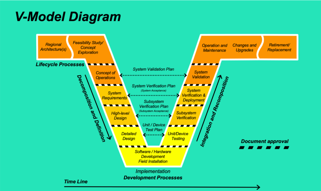
The V-Process, often referred to as the “Verification and Validation Process,” follows a well-defined path that resembles the letter “V,” representing the sequential nature of its execution. This model is renowned for its holistic approach, bridging the gap between the initial requirements definition and the final testing and integration. Essentially, we can break down the V-Process into two primary parts:
Part 1: Requirements Definition to Detailed Design
The first leg of the “V” kicks off with Requirements Definition. This step involves a thorough understanding of client requirements and translating them into detailed specifications. As the foundation of the entire process, accurate requirements are crucial to avoid costly rework later in the project.
Next comes System Architecture and High-Level Design, where the overall system architecture is designed. It lays the groundwork for subsequent stages and ensures alignment with client expectations.
Moving down the left side of the “V,” we encounter Component Design and Implementation. Here, the system architecture consists of smaller components, with detailed designs. Actual coding takes place during this step, leading to the creation of individual system elements.
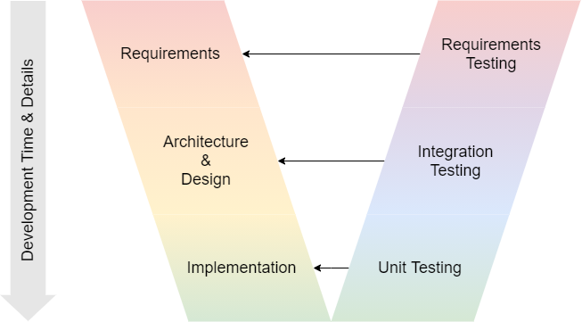
The bottom point of the “V” represents Unit Testing, where we test the component’s functionality in isolation. This phase ensures that individual pieces of the system function as intended before moving forward.
Finally, on the right side of the “V,” we have Integration Testing. During this step, individual components are combined and tested collectively to ensure their seamless integration. Any compatibility issues or inter-component communication problems are addressed here.
Part 2: Testing and Integration in the Global System
The second phase of the V-Process shifts focus towards testing and integration into the global system. It starts with System Testing, where the entire system is tested as a whole. This is the first time the complete system’s functionality is evaluated, allowing for the identification of any system-wide issues.
Following System Testing, the journey leads to Validation Testing, where the system is validated against the initial requirements. This step confirms whether the system meets the client’s expectations and functions correctly in its intended environment.
Continuing upward, we reach User Acceptance Testing (UAT). This stage involves end-users testing the system in a real-world environment to ensure it aligns with their needs. Feedback from UAT is invaluable for fine-tuning the system.
The final step of the V-Process is Deployment and Maintenance. Maintenance activities ensure the system’s long-term functionality and address any unforeseen issues that may arise during usage.
SCRUM in Every Step
A noteworthy aspect of the V-Process is its integration of SCRUM methodologies in every step. SCRUM is an agile framework that promotes iterative and incremental development, enhancing flexibility and adaptability in project management. By incorporating SCRUM, the V-Process ensures that each phase benefits from the agility and collaboration inherent in the approach.
Dive into Scrum Methodology Overview from WiredWhite
V-Process Typical Implementation and Significance
The V-Process finds its natural fit in domains like software development and system engineering, where intricate planning and precision are essential. Its structured approach minimizes risks, enhances quality, and ensures that the final product aligns closely with the client’s vision.
Consider a scenario where a company is gearing up to launch a new car model. In this complex endeavor, you must meet numerous certifications and compliance standards. Enter the V-Process, which provides a roadmap for development that aligns with these rigorous requirements.
When it comes to software development, auditors play a pivotal role in certifying the product’s adherence to established standards. One such critical certification is ISO 26262, which focuses on functional safety for automotive software systems. The V-Process shines here as it facilitates a transparent and traceable development cycle, making it easier to demonstrate compliance during audits.
Summary
The V-Process is more than a model; it’s a philosophy that embodies methodical planning, rigorous testing, and continuous improvement. Its dual-phased structure, each consisting of carefully orchestrated steps supported by SCRUM, ensures that projects progress with precision and agility. In industries where compliance, quality, and precision are paramount, like software development and system engineering, the V-Process stands as a guiding beacon toward successful project execution. So, the next time you encounter a new car model on the streets, remember that beneath its sleek exterior lies a journey guided by the V-Process, ensuring safety, quality, and compliance every step of the way.


Responses