

Servo Drive System with Optimum Braking Strategy Using State-Space Control in a PMSM-Based Electromechanical Platform

Author: Waqas Javaid
Abstract
This paper presents a comprehensive analysis of a servo drive system developed in a multi-domain simulation environment, combining electrical, mechanical, and control subsystems. The studied configuration includes a voltage source inverter using space vector pulse width modulation (SVPWM), a surface-mounted permanent magnet synchronous machine (PMSM), and a ball screw-based mechanical transmission system driving a linear slide with end-stop constraints. A state-space controller is implemented for high-bandwidth position regulation, incorporating both conventional fixed speed limiting and an advanced optimum speed limiting strategy to mitigate limit cycles and mechanical impacts. Simulation results demonstrate that while conventional limiting leads to overshoot and oscillatory behavior due to mechanical backlash and torque saturation, the optimum braking strategy significantly improves transient response and eliminates hard-stop collisions. The study highlights the importance of integrated electro-mechanical control design in high-precision servo applications.
I. Introduction
Modern industrial servo systems demand high precision, fast dynamic response, and robust operation under nonlinear mechanical constraints. Applications such as CNC machining, robotics, and automated manufacturing require accurate position tracking with minimal overshoot and vibration. These requirements become challenging when electrical drives interact with mechanical elements such as gear backlash, shaft compliance, and hard mechanical stops.
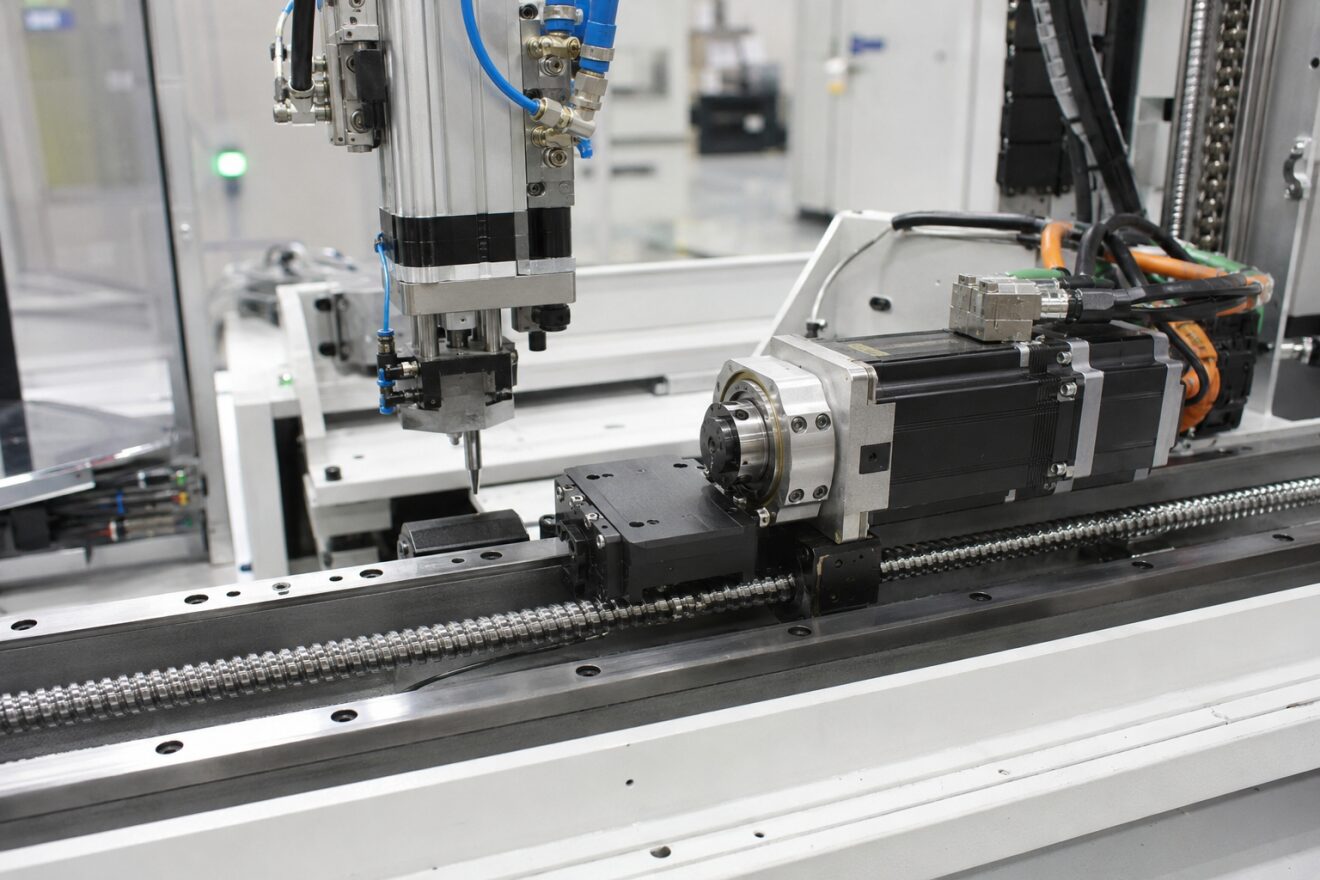
Figure 1: High-precision industrial servo drive system with PMSM-based ball screw actuator in a modern automated manufacturing environment
Figure 1 illustrates a real-world industrial servo positioning system used in precision automation and manufacturing applications. It shows a high-performance electromechanical setup integrating a permanent magnet synchronous motor (PMSM), ball screw linear actuator, and a precision guide rail system.
On the right side, a servo motor assembly is coupled to a ball screw mechanism that converts rotary motion into highly accurate linear displacement. The motor is equipped with rigid housing, encoder feedback, and power cables for closed-loop control operation. The mechanical transmission includes a threaded ball screw shaft supported by linear bearings, ensuring smooth and low-friction motion.
On the left side, a tool head or actuator spindle is visible, likely representing a machining or positioning head used for manufacturing operations such as milling, drilling, or precision placement. The vertical actuator is connected to a rigid frame structure, allowing controlled motion along a defined axis.
The entire system is mounted on a robust industrial base structure designed to minimize vibration and improve positioning accuracy. Electrical wiring and pneumatic lines are visible, indicating integration of multi-domain control (electrical, mechanical, and possibly pneumatic systems).
This setup represents a typical servo-driven precision positioning platform used in CNC machinery, robotics, and automated production lines, where high repeatability, fast response, and minimal positional error are critical performance requirements.
Permanent magnet synchronous machines (PMSMs) are widely used in servo applications due to their high torque density and efficiency. When combined with field-oriented control (FOC), PMSMs can achieve decoupled torque and flux control, enabling high-performance dynamic behavior [3]. However, mechanical nonlinearities such as backlash and inertia coupling often introduce oscillations and instability in closed-loop systems.
In this study, a complete servo drive system is analyzed using a multi-domain simulation platform. The system integrates:
- A three-phase inverter with SVPWM
- A digital synchronous frame current regulator
- A PMSM coupled to a ball screw mechanism
- A state-space position and speed controller
- A mechanical load with backlash and hard stop
The key focus is on comparing conventional fixed speed limiting with an optimum speed limiting strategy that improves braking performance and eliminates oscillatory limit cycles.
II. System Description
A. Electrical Subsystem
The electrical drive consists of a voltage source inverter modeled as an ideal three-phase bridge supplied by a stiff DC bus. The inverter output is controlled using space vector pulse width modulation (SVPWM), which optimally utilizes the DC link voltage and reduces harmonic distortion [4].
The stator currents are measured and transformed into the synchronous dq reference frame using Clarke and Park transformations. This enables independent control of torque-producing and flux-producing current components. The inverter feeds a PMSM whose electromagnetic torque is governed by the interaction between stator currents and rotor magnetic flux.
B. Mechanical Subsystem
The mechanical system includes a PMSM shaft connected to a ball screw via a compliant coupling. The ball screw converts rotary motion into linear displacement of a sliding platform carrying the workpiece.
Key mechanical components include:
- Shaft inertia
- Elastic shaft stiffness
- Mechanical damping
- Backlash in coupling
- Hard stop constraint at end of travel
Backlash introduces dead zones in motion transmission, leading to oscillations when direction reversals occur. The hard stop introduces a nonlinear discontinuity that can cause impact forces if braking is not properly controlled.
You can download the Project files here: Download files now. (You must be logged in).
C. Control Subsystem
The control architecture consists of a hierarchical structure:
- Outer loop: State-space position controller
- Inner loop: Digital synchronous frame current controller
- Modulation stage: SVPWM generator
The state-space controller operates in per-unit form and regulates both position and speed. It includes anti-windup mechanisms and state limiting to prevent integrator saturation.
Two speed-limiting strategies are considered:
- Fixed speed limit (1 p.u.)
- Optimum speed limit (adaptive based on position error)
The optimum method dynamically adjusts velocity constraints to ensure sufficient braking distance before reaching the target.
III. Mathematical Modeling
A. Electromechanical Torque Relationship
The electromagnetic torque of the PMSM in dq reference frame is given by [3]:

Equation (1) shows that torque is directly proportional to q-axis current, forming the basis of field-oriented control [3].
B. Optimum Speed Limiting Law
The optimum braking strategy can be expressed as a constraint on reference speed [1][2]:
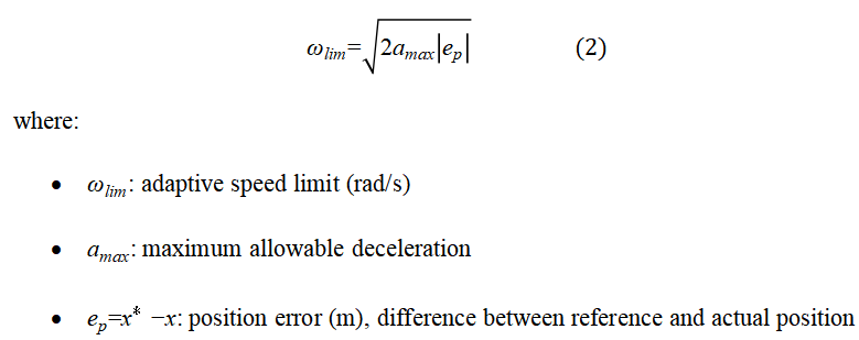
This equation ensures that the system always maintains sufficient deceleration capability to reach the target without overshoot. It is derived from classical motion equations under constant deceleration assumptions [1][2].
IV. Control Strategy Implementation
A. Fixed Speed Limiting
In the fixed strategy, motor speed is constrained to a constant limit (1 p.u.), independent of system state. While this ensures safety under nominal conditions, it fails under large position steps. The inability to dynamically adjust braking distance leads to overshoot and oscillatory behavior.
B. Optimum Speed Limiting
The adaptive strategy modifies the allowable speed based on real-time position error. As the system approaches the target, the speed limit reduces proportionally, ensuring smooth deceleration.
This method effectively introduces a predictive braking mechanism without requiring full trajectory planning. It significantly reduces reliance on reactive torque switching, thereby minimizing limit cycles.
C. State-Space Controller
The outer loop controller uses a state-space representation of the servo dynamics, incorporating:
- Position state
- Velocity state
- Integral correction state
Anti-windup logic prevents integrator divergence during saturation. The controller outputs torque reference, which is converted to i*q for current regulation.
V. Simulation Setup
The system is implemented in a multi-domain simulation environment where electrical, mechanical, and control subsystems interact in real time.
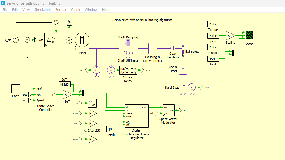
Figure 2: Servo Drive with Optimum Braking System Circuit Development in PLECS Simulation
Figure 2 presents the complete servo drive system implemented in the PLECS simulation environment with the proposed optimum braking strategy enabled. The system integrates electrical, mechanical, and control domains into a unified multi-physics model.
On the electrical side, the model consists of a three-phase voltage source inverter controlled using Space Vector Pulse Width Modulation (SVPWM), which ensures efficient DC-link utilization and reduced harmonic distortion in the output voltage. The inverter supplies a permanent magnet synchronous motor (PMSM) that converts electrical energy into mechanical torque.
The control architecture shown in Figure 2 includes a high-performance state-space controller operating in a per-unit system. This controller generates a torque reference based on position and speed errors. Unlike conventional approaches, the controller incorporates an optimum speed limiting mechanism, which dynamically adjusts the allowable velocity based on remaining distance to the target position. This ensures that the system has sufficient deceleration capability before reaching the reference position, thereby preventing overshoot and hard-stop collision.
The mechanical subsystem includes a ball screw mechanism, gear coupling, shaft inertia, backlash, and damping elements. These components realistically model transmission losses and nonlinearities that strongly affect servo performance. The slide mechanism represents the final mechanical output, which is position-controlled for precision motion applications such as machining or automated manufacturing.
Overall, Figure 2 illustrates the integrated servo architecture where electrical drive, advanced control, and mechanical load interaction are co-simulated to evaluate system-level performance under realistic operating conditions.
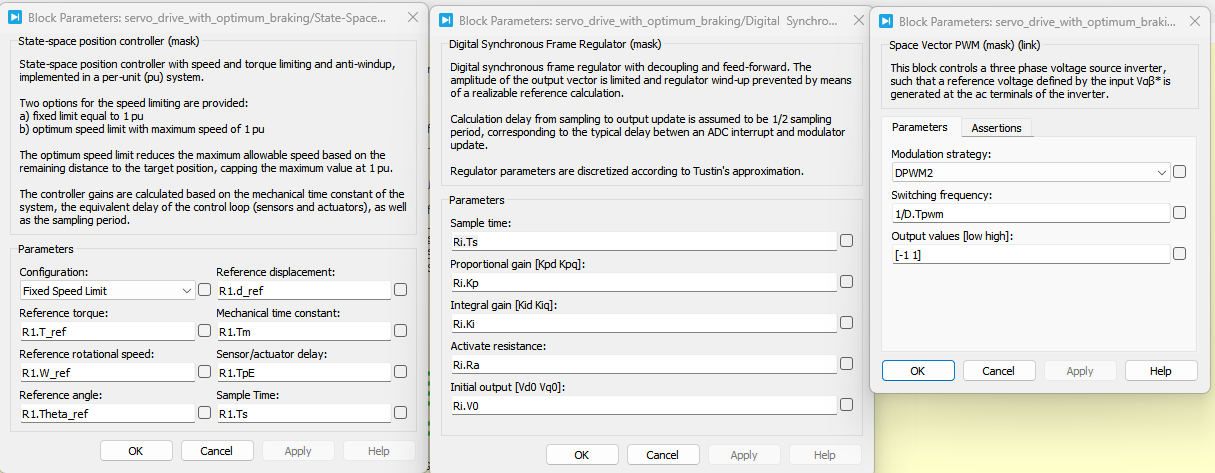
Figure 3: Block Parameters of State Space Controller with Digital Synchronous Regulator and SVPWM in PLECS Simulation
You can download the Project files here: Download files now. (You must be logged in).
Figure 3 illustrates the internal control structure of the servo drive, focusing on the state-space controller, digital synchronous frame regulator, and SVPWM modulation block.
The state-space controller acts as the outer-loop regulator, processing position reference signals and generating a torque demand. It is designed in a structured state-feedback form, enabling fast dynamic response and stable closed-loop behavior. Anti-windup mechanisms are included to prevent integrator saturation during torque or speed limiting conditions.
The torque reference generated by the state-space controller is converted into a quadrature-axis current reference (i_q*), which serves as the input to the inner current control loop. This conversion is based on the PMSM electromechanical torque relationship, where torque is directly proportional to q-axis current.
The digital synchronous frame regulator operates as the inner-loop current controller. It regulates both d-axis and q-axis currents using decoupled PI controllers in the rotating reference frame. This ensures that flux and torque components are controlled independently, improving dynamic performance and stability.
Finally, the regulated voltage commands are passed to the Space Vector PWM (SVPWM) modulator, which generates switching signals for the inverter. SVPWM optimizes voltage utilization by synthesizing a rotating voltage vector, ensuring smooth motor operation and reduced harmonic distortion.
Figure 3 therefore represents the hierarchical control architecture of the servo drive, where outer-loop motion control, inner-loop current regulation, and inverter modulation work together to achieve high-precision positioning.
Two test scenarios are evaluated:
- Small step input (1 mm)
- Large step input (5 cm)
For each case, both fixed and optimum speed limiting strategies are tested. The simulation captures:
- Motor torque response
- Slide position tracking
- Velocity profiles
- Impact of mechanical constraints
VI. Results and Discussion
A. Small Step Response
Under a small position step (1 mm), the system with fixed speed limiting demonstrates stable behavior with minimal overshoot. However, due to mechanical backlash, a small oscillation persists around the setpoint.
This phenomenon is attributed to dead-zone dynamics in the ball screw coupling. Reducing backlash reduces oscillation amplitude significantly, confirming its mechanical origin.
B. Large Step Response with Fixed Limiting
For a 5 cm step input, the system exhibits severe overshoot and collision with the hard stop. The motor reaches torque saturation, causing a bang-bang control effect where torque alternates between maximum acceleration and deceleration.
This behavior results in a limit cycle characterized by:
- High overshoot
- Mechanical impact
- Extended settling time
Such behavior is undesirable in precision servo systems and may cause mechanical wear.
C. Large Step Response with Optimum Limiting
When the optimum speed limiting strategy is enabled, system performance improves significantly:
- Overshoot is drastically reduced
- Hard stop collision is eliminated
- Settling time is minimized
- Smooth deceleration profile is achieved
The adaptive speed constraint ensures that the system always has sufficient braking distance, preventing energy accumulation in mechanical inertia.
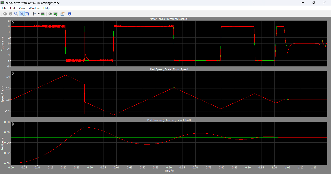
Figure 4: Motor torque with actual and reference curve generated, Part speed and Scaled Motor Speed graphs, Part Position graphs of reference and actual are generated by PLECS Simulation
You can download the Project files here: Download files now. (You must be logged in).
Figure 4 presents the dynamic simulation results of the servo system when the optimum speed limiting (optimum braking) strategy is enabled for a large position step input.
The first subplot shows motor torque response, where torque initially rises to accelerate the load and then smoothly transitions into a controlled braking phase. Unlike the fixed speed limit case, torque does not oscillate between extreme saturation values. Instead, it follows a smoother profile, indicating that the controller is effectively managing energy dissipation during deceleration.
The second subplot illustrates part speed and scaled motor speed. The velocity increases during acceleration and then gradually decreases as the system approaches the target position. Importantly, the speed profile is no longer abrupt; instead, it is shaped by the adaptive speed constraint, which continuously reduces allowable velocity based on remaining position error. This ensures that the system avoids excessive kinetic energy buildup, preventing overshoot and mechanical impact.
The third subplot shows part position tracking, comparing reference and actual position. The results demonstrate accurate tracking with minimal overshoot and fast settling time. The system reaches the desired position smoothly without oscillations or repeated corrections, which were observed in the fixed speed limit case.
Overall, Figure 4 confirms the effectiveness of the optimum braking strategy in improving transient response, eliminating limit cycles, and ensuring safe deceleration before reaching mechanical constraints such as hard stops.
VII. Discussion on Stability and Performance
The results demonstrate that servo system performance is not solely dependent on electrical control quality but also on mechanical-aware control strategies. The inclusion of mechanical constraints in control design is essential for high-performance applications.
Key observations include:
- Backlash introduces nonlinear oscillations
- Fixed limits are insufficient for large dynamic transitions
- Adaptive braking significantly improves stability margins
- Integrated electro-mechanical modeling is essential for accurate prediction
The study confirms that optimum braking acts as a form of predictive control, improving both safety and efficiency.
VIII. Practical Implications
The proposed approach is highly relevant for:
- CNC machine tool control
- Robotics joint actuation
- Precision positioning systems
- Automated manufacturing lines
By incorporating adaptive speed limiting, industrial systems can reduce mechanical stress and increase operational lifespan.
IX. Conclusion
This paper presented a detailed analysis of a PMSM-based servo drive system with advanced control and mechanical coupling. A comparison between fixed and optimum speed limiting strategies demonstrated the superiority of adaptive braking in reducing overshoot, eliminating limit cycles, and improving dynamic performance.
The integration of state-space control with real-time adaptive constraints ensures robust operation under nonlinear mechanical conditions. Future work may include experimental validation and extension to multi-axis coordinated motion systems.
References
[1] H. Bühler, Réglage de systèmes d’électronique de puissance, vol. 1: Théorie, Presses Polytechniques et Universitaires Romandes, Lausanne, 1997.
[2] H. Bühler, Réglage de systèmes d’électronique de puissance, vol. 2: Théorie, Presses Polytechniques et Universitaires Romandes, Lausanne, 1997.
[3] R. Krishnan, Electric Motor Drives: Modeling, Analysis, and Control, Prentice Hall, 2001.
[4] B. K. Bose, Modern Power Electronics and AC Drives, Prentice Hall, 2002.
You can download the Project files here: Download files now. (You must be logged in).







Responses