

PMSM Hairpin Winding FEA Simulation & Validation Using Ansys Maxwell
Hairpin windings with parallel branches often exhibit unequal current sharing caused by differences in induced electromotive force (EMF) and AC resistance.
WiredWhite validated the winding layout of a 6-phase permanent magnet synchronous motor (PMSM) with parallel hairpin windings using advanced 3D electromagnetic finite element analysis in Ansys Maxwell.
Industry
Automotive
Product
Hybrid Electric Vehicles, Electric Vehicles, BAS
Service
FEA Modelling & Simulation
Technical Stack
Ansys Maxwell
Duration
6 months
Client
Confidential / Tier 1 Supplier
Project Objectives
- Validate Winding Symmetry & Topology: Verify six-phase topology, weak, and strong winding symmetry prior to manufacturing.
- Identify Current Imbalance: Analyze exact current distribution across every individual parallel branch.
- De-risk Prototype Build: Pre-emptively detect circulating currents, copper losses, and local hot spots before physical prototype tooling.
- Validate Across Operating Range: Evaluate parallel branch performance under multiple speed and load operating conditions.
- Increase efficiency by reducing the current imbalance in parallel hairpin windings.
- Reduce development time or prototype iterations and thus the development costs.
The Challenge
The given motor suffered from unchecked current imbalances, which created circulating currents across parallel branches, resulting in increased copper losses, severe local thermal hot spots, and reduced overall motor efficiency and reliability.
Constraints:
- Size / Weight: Localized thermal hot spots from unbalanced currents force conservative oversizing of cooling jackets or conductor cross-sections to prevent thermal failure, adding unnecessary volume and mass to the electric drive unit.
- Cost Targets: Unidentified current imbalances discovered during physical testing lead to expensive prototype scrap, costly stator tooling revisions, and extended redesign cycles.
- Material Limitations: Peak temperatures driven by localized circulating currents can exceed the thermal ratings of slot insulation, enamel coatings, and surrounding materials, accelerating thermal degradation and risk of dielectric breakdown.
- Performance Requirements: High circulating currents increase parasitic copper losses, directly degrading overall motor efficiency, continuous torque output, and long-term operating reliability across the drive cycle.
Physical prototyping without prior simulation hides branch-level circulating currents, risking costly hardware redesigns, delayed development schedules, and potential thermal failure during bench testing.
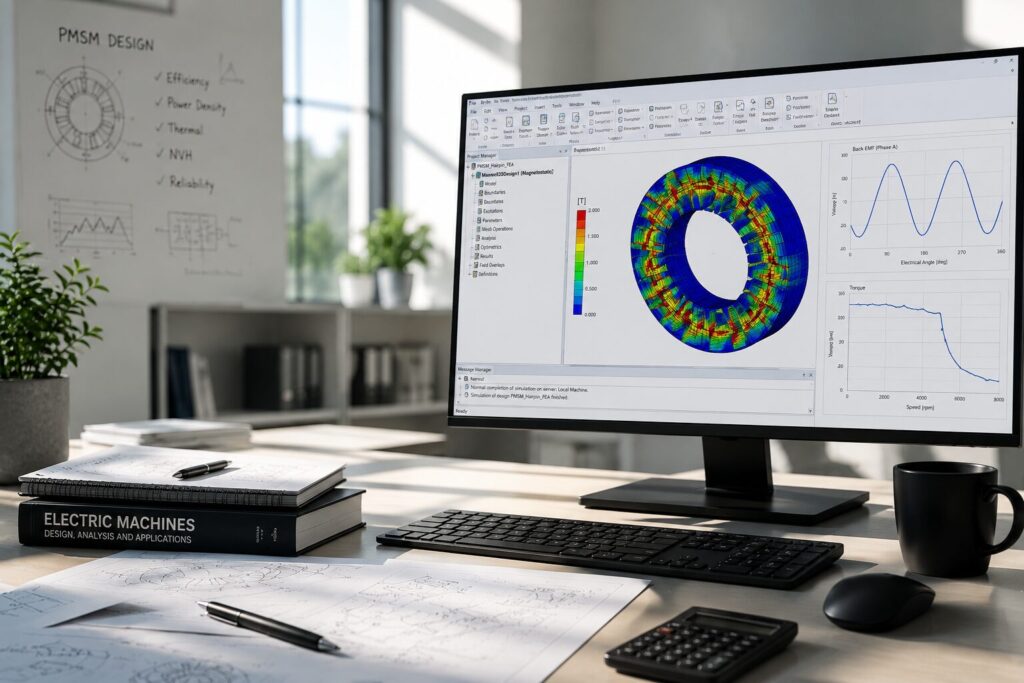
Conventional workflows often assume uniform current distribution across parallel branches. Our case study demonstrates a 3D CAD-driven Maxwell FEM workflow that resolves individual branch circuits dynamically.
Our Solution
In order to achieve the project goals the following approach and workflow was applied:
1️⃣ Reconstructed the customer’s full 3D CAD winding design.
2️⃣ Conducted weak & strong symmetry evaluations for the 6-phase topology.
3️⃣ Generated a complete Finite Element Maxwell electromagnetic model directly from CAD data.
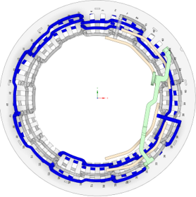
4️⃣ Connected a dedicated external circuit simulator to the Maxwell FEA model to allow independent branch currents and voltages to be solved dynamically.
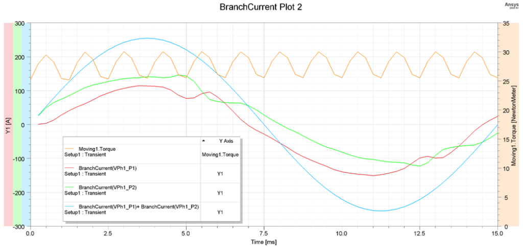
5️⃣ Analyzed flux density distributions and transient current waveforms across multiple operating points.
Technical Stack
- FEA Solver: Ansys Maxwell (Electromagnetic Simulation).
- Circuit Co-Simulation: Integrated external circuit simulator for detailed branch circuit analysis.
Model Parameters & Geometry
- Model Type: Full 2D Electromagnetic Model.
- Components Included: Complete stator winding, all 6 phases, and every individual parallel branch with full 2D electromagnetic coupling.
- Circuit Coupling: External circuit wired to resolve independent branch voltages and individual branch currents directly.
Simulation Scenarios
Six transient electromagnetic simulations were performed across combinations of rotational speed and phase current loads:
- 1000 rpm @ 180 ARMS
- 1000 rpm @ 90 ARMS
- 2000 rpm @ 180 ARMS
- 2000 rpm @ 90 ARMS
- 3000 rpm @ 180 ARMS
- 3000 rpm @ 90 ARMS
Results
Key Findings
- Widespread Current Imbalance: Unequal current distribution was observed across all investigated operating points.
- Dual Root Causes: Findings confirmed that both induced EMF asymmetry and AC resistance differences contribute significantly to the parallel branch current imbalance.
- Speed/Load Consistency: Imbalance persists across low-to-high speed ranges and partial-to-full load conditions.
- Thermal & Loss Impact: Identified severe circulating currents that would lead to elevated copper losses, local hot spots, and reduced operational efficiency.
| Parameter / Aspect | Initial Design (Pre-Simulation Analysis) | Electromagnetic Co-Simulation Findings |
|---|---|---|
Current Distribution | Assumed equal sharing across parallel branches | Unequal current distribution verified across all 6 operating points. |
Circulating Currents | Unquantified risk | High circulating currents detected in parallel branches. |
Root Cause Drivers | Unknown | Induced EMF asymmetry & AC resistance differences. |
Thermal Risk | High risk of hidden local hot spots | Identified beforehand, enabling layout correction before build. |
Business Impact of PMSM Hairpin Winding FEA Simulation
🛡️Risk Reduction Before Manufacturing
Identified branch imbalance and circulating current issues before committing to expensive physical tooling and prototype builds.
💰 Development Cost & Time Savings
Saved prototype iterations and avoided costly hardware failures during bench testing.
⬆️ Increased Design Confidence
Provided full electromagnetic validation and verified complete 6-phase winding performance under realistic loading conditions.
See even more technical details in the case study.
What You’ll Learn in the Case Study
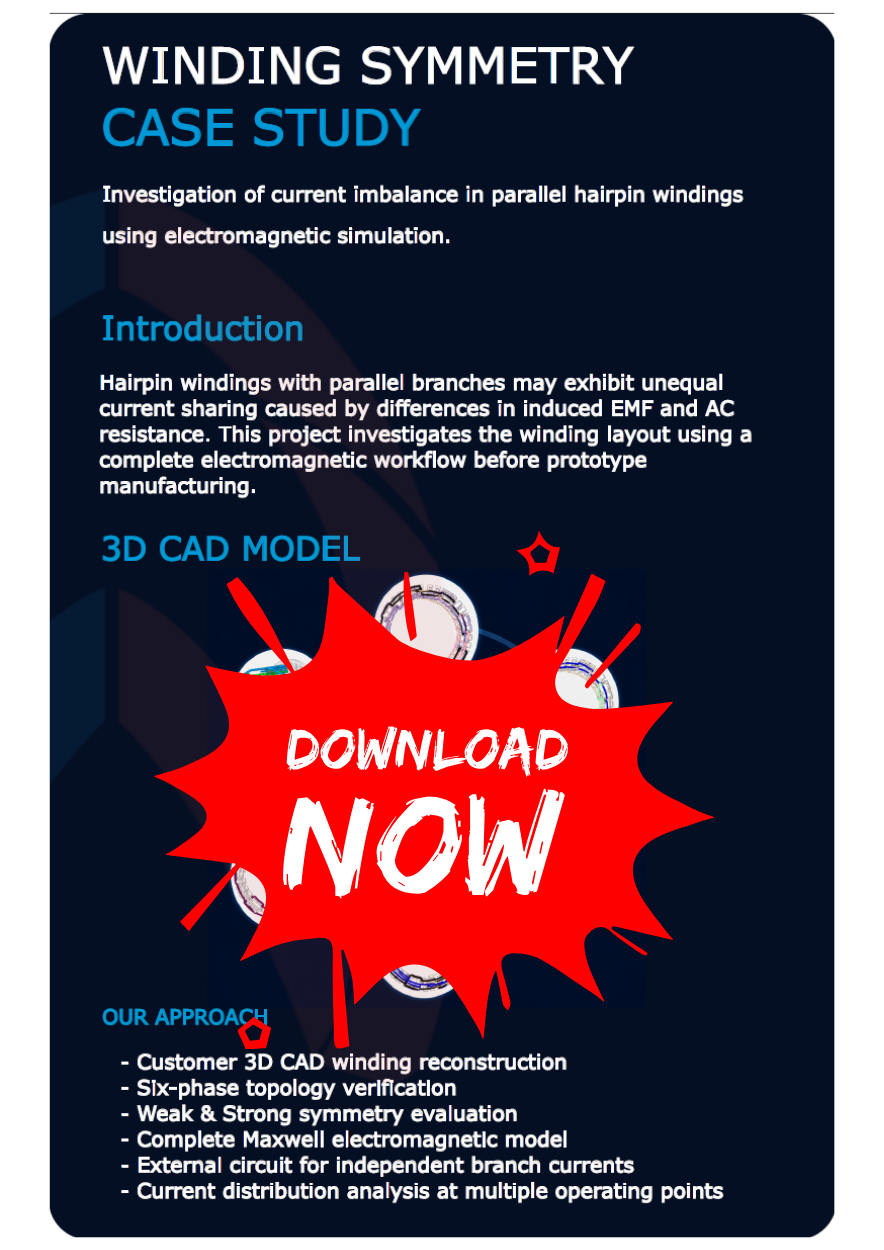
In just 5 minutes read-time, our Case Study will give you a detailed technical insight into the process and results of investigating a current imbalance in parallel hairpin windings using electromagnetic simulation.
You’ll get to see:
- A 3D CAD Model
- A description of our approach
- The full model in Ansys Maxwell
- The External Circuit & Flux Density Result
- The current in parallel branches
- An overview of our key findings and learnings.
Why WiredWhite is the Perfect Engineering Partner for You
⏱ 15+ Years
industry experience
👨 1000+
networked engineering professionals
🔄 Integrated
project collaboration tools
✅ 100%
Proficient in advanced engineering tools
This Case Study is Perfect for:
- Engineering Directors of Electric Drives Division
- R&D Engineering Manager
- Electric Motor Design Engineers
- EV Powertrain/ Traction Motor Engineer
- CEOs/ COOs /CTOs
Download the Case Study
Please fill out the form below and comfirm the Opt-in mail to receive the document right into your mail box.
*WiredWhite needs the contact information you provide to us to contact you about our products and services or to comply with our contractual services. You may unsubscribe from these communications at any time. For more information, please review our Privacy Policy.





