

Case Study: Modeling and Simulation of a 12 V Vehicle Power Network in MATLAB Simulink
Model-Based Development · Automotive Engineering · System Simulation & Validation
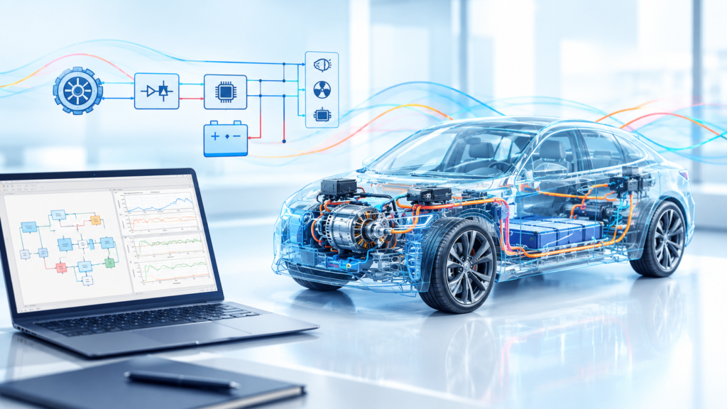
WiredWhite developed a modular MATLAB Simulink model of a vehicle’s low-voltage power network to support the analysis of electrical system behavior under automotive operating conditions.
The project combined synchronous machine modeling, excitation-current control, power-electronics simulation, and validation against test-bench measurements to provide a reliable basis for system analysis and development.
Industry
Automotive
Product
Hybrid Electric Vehicles, Electric Vehicles, BAS
Service
Model-Based Software Development
Technical Stack
MATLAB Simulink
Duration
6 months
Client
Confidential
Project Overview & Objectives
The Product:
A modular 12 V vehicle electrical power network simulation architecture developed in MATLAB Simulink.
Why It Was Necessary:
Electrical network simulation is a critical tool in modern automotive design to analyze power electronics, calculate system losses, and evaluate dynamic control strategies prior to physical prototyping.
Where It Was Used:
In automotive research and development environments for investigating 12 V power grids and evaluating engine-alternator interaction test cases.
Task Solved:
The model simulates the complete 12 V power architecture—including alternator voltage regulation, battery charging, dynamic electrical loads, and engine start-up sequences—to ensure electrical grid stability and prevent alternator drag during engine ignition.
Project objectives:
- System-level analysis: Understand how the alternator, battery, rectifier, and electrical loads interact under different operating conditions.
- Modular architecture: Enable individual components to be adjusted, parametrized, or replaced without rebuilding the entire model.
- Control-system development: Model and tune the alternator’s excitation-current control loop.
- Automotive scenario simulation: Investigate electrical behavior during engine starting and other representative operating conditions.
- Model validation: Compare simulation results with laboratory test-bench measurements to assess the model’s ability to reproduce real system behavior.
The Challenge
A vehicle’s low-voltage electrical network is a dynamic system in which generator output, electrical loads, battery behavior, and control-system responses influence one another.
The challenge was to represent these interactions in a simulation environment detailed enough to investigate automotive operating scenarios while maintaining a flexible, modular model architecture.
The main engineering challenges were:
01
Accurate Machine Saturation Modeling:
Stator self-inductance exhibits strong magnetic saturation non-linearities under varying armature and field currents, requiring non-linear modeling beyond standard linear inductances.
02
High-Frequency Excitation Control:
Real-world claw-pole alternators utilize rapid pulse-width modulation (PWM) switching with hysteresis to regulate field current, demanding accurate closed-loop PI controller reproduction in software.
03
Engine Ignition Drag Mitigation:
Because the generator is mechanically coupled to the internal combustion engine (ICE), engaging alternator output during engine cranking introduces unwanted torque resistance, hindering ignition.
04
Empirical Model Validation:
Simulation waveforms required rigorous verification against empirical data from a physical test bench to prove model fidelity.
Our Solution
WiredWhite applied a model-based software development approach, covering component modeling, control-loop tuning, system simulation, and validation.
Step 1: Modular Symbiotic Architecture
Developed a modular framework in Simulink/MATLAB integrating analytical equations, lumped parameter component sub-models, and SimPowerSystems blocks for easy component replacement.
Step 2: Six-Phase Claw-Pole Alternator Sub-Model
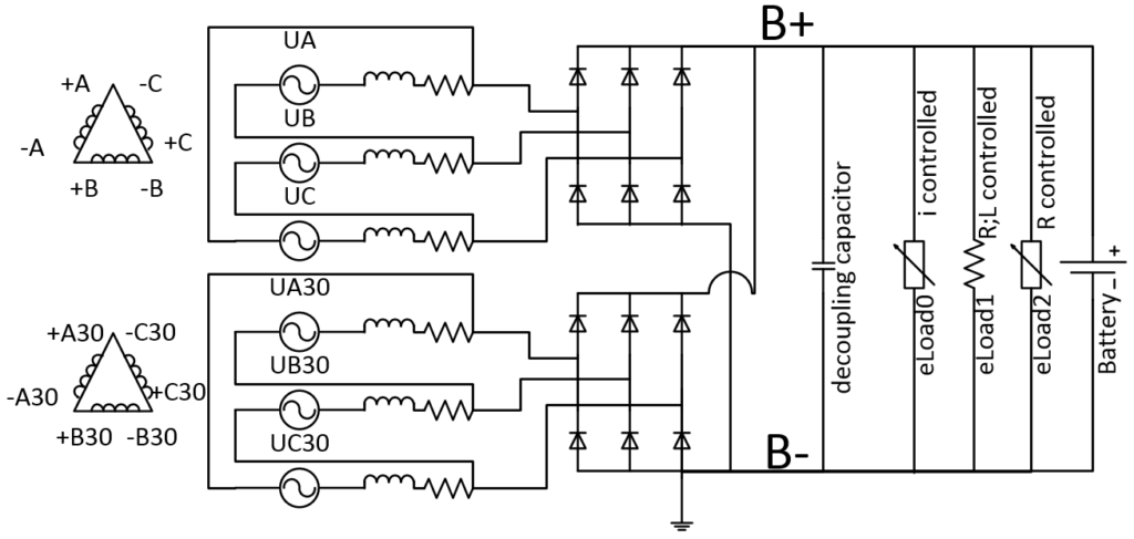
Built an individual six-phase machine model that calculates internal machine voltage based on speed and excitation current while adjusting phase inductances dynamically to account for magnetic saturation.
Step 3: Automotive Excitation Control Loop:
Implemented a hysteresis PI controller with a 10.6 V trigger threshold and a 7.75 A current limit, replicating the 1000 Hz switching frequency of real vehicle transistor output stages.
Step 4: Integrated Grid Sub-Models
Connected two parallel-connected passive rectifier bridges (Zener/Schottky diodes), dynamic electronic loads (current-controlled, resistive, resistive-inductive), and a nickel-metal hydride (NiMH) battery block with monitoring sensors.
Step 5: Engine Start-Up Test Case Simulation
Simulated the “influence of alternator on start performance of ICE” by maintaining the alternator in an inactive state during engine cranking until the engine stabilized at idle speed.

Need Support With Your Automotive Simulation Project? Contact WiredWhite to discuss your engineering requirements.
Technical Stack
MATLAB & Simulink
Used for overall system modeling, control algorithm execution, lumped parameter sub-models, and SimPowerSystems electrical grid block integration.
Finite Element Method (FEM) Tools
Used to extract experimental stator resistance and self-inductance parameters under saturated conditions.
Physical Test Bench Hardware
Utilized a custom-built physical test bench featuring a DC motor (simulating the ICE drive), a physical six-phase claw-pole alternator, sensor arrays, and oscilloscopes for empirical verification.
Results & Empirical Validation
To evaluate model fidelity and grid stability, the simulation was validated against physical test bench measurements under full generator load at nominal engine speed. The model successfully demonstrated closed-loop voltage regulation, accurate power distribution, and dynamic engine torque relief:
1️⃣ 12 V Grid Power Balance
At a regulated 13.5 V DC grid voltage, the alternator produced a total mean output of 80 A , delivering 60 A to charge the battery while simultaneously powering a 20 A active load.
2️⃣ Excitation Control Precision:
The closed-loop PI controller capped field current at 7.75 A operating at a 1000 Hz PWM frequency, with active control triggering reliably above 10.6 V.
3️⃣Engine Torque Drag Relief:
During engine ignition (initiated at 4.0 s), generator activation was intentionally held back until 7.0 s. This 3.0-second startup delay completely eliminated alternator torque resistance during engine cranking until stable idle speed was reached.
4️⃣High Predictive Accuracy:
Confirmed strong qualitative and quantitative alignment between simulated voltage/current transient waveforms and physical test bench measurements.
Transform your electrical architecture R&D with validated co-simulation models. Reduce physical prototypes, optimize control strategies, and accelerate time to market.
Why WiredWhite is the Perfect Engineering Partner for You
⏱ 15+ Years
industry experience
👨 1000+
networked engineering professionals
🔄 Integrated
project collaboration tools
✅ 100%
Proficient in advanced engineering tools
- Free consultation call
- Contact form
Contact us now.
Speak directly with our experts to explore how we can help you model, simulate, and validate your engineering projects.





