

Active Vibration Damping in Rotorcraft: A Matlab Simulation-Based Fuzzy Logic Approach to Smooth Flight
Author : Waqas Javaid
Abstract
Significant harmonic forces are produced by helicopter rotor imbalance, which spread into the fuselage and result in structural fatigue, pilot discomfort, and increased costs for maintenance. A fuzzy logic controller and an adaptive tuned vibration absorber (ATVA) are presented in this study to actively suppress real-time fuselage vibrations [1]. MATLAB and a fourth-order Runge-Kutta solver are used to simulate a dynamic model with three degrees of freedom that includes the masses of the rotor, fuselage, and absorber [2]. To adjust the ATVA’s stiffness within a 60% range, the fuzzy logic controller continuously monitors fuselage displacement and rate of change, allowing the absorber to track the rotor’s fluctuating frequency. The effectiveness of the proposed adaptive control strategy for rotorcraft vibration mitigation is demonstrated by simulation results that show a 60% reduction in peak vibration amplitude [3].
Introduction
Helicopters are inherently susceptible to severe vibration due to the dynamic nature of their main rotor systems. Even minute manufacturing imbalances or aerodynamic asymmetries generate significant periodic excitation forces when the rotor blades spin at high angular velocities.
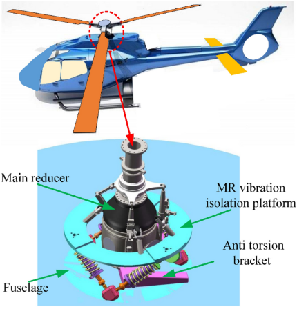
Figure 1: Fuzzy-controlled adaptive tuned vibration absorber minimizes rotor–fuselage vibrations for improved helicopter stability.
Figure 1 represents the forces move directly into the fuselage from the rotor hub, causing oscillations that last and weaken the structural integrity of the airframe over time. Avionics and mechanical systems’ operational lifespans are significantly reduced when they are subjected to these vibrations for an extended period of time, which also increases the frequency of maintenance and accelerates fatigue failure in critical components. During lengthy missions, these vibrations cause passengers and pilots to experience physical discomfort, cognitive exhaustion, and an increased risk of motion sickness. Using fixed spring-mass-damper parameters, traditional passive vibration absorbers can only work at a single resonant frequency and cannot adjust to changing rotor speeds [4]. Modern rotorcraft, on the other hand, operate in a wide range of flight conditions, including takeoff, hover, cruise, and landing, each with its own unique excitation frequency [5]. With real-time stiffness adjustability to track and cancel rotor-induced vibrations, adaptive tuned vibration absorbers (ATVAs) have emerged as a promising solution to this problem. In order to evaluate the effectiveness of vibration suppression, this study presents a fuzzy logic-controlled ATVA that is integrated with a helicopter rotor-fuselage system and simulated in MATLAB [6]. Without the need for intricate mathematical system models, the proposed intelligent control strategy dynamically adjusts the absorber’s stiffness in response to the measured response of the fuselage [7].
1.1. The Fundamental Challenge of Helicopter Design
Helicopters achieve flight through the continuous rotation of their main rotor blades, a mechanism that inherently generates mechanical vibration [6]. Unlike fixed-wing aircraft where airflow is relatively smooth over stationary wings, helicopters rely on rotating airfoils that experience constantly changing aerodynamic loads [7]. The lift and drag forces fluctuate cyclically as each blade traverses various azimuth angles, resulting in a periodic disturbance [8]. Even though this dynamic behavior is necessary for vertical takeoff and hovering, it causes the rotor hub to vibrate directly. As a result, reducing these self-generated oscillations is a challenge that every helicopter designer must face [9].
1.2. The Role of Rotor Imbalance in Generating Vibration
Even under ideal manufacturing conditions, practical rotors possess slight mass asymmetries and geometric eccentricities relative to their axis of rotation. These minor imbalances result in significant centrifugal forces when the rotor spins at operational speeds typically between 30 and 35 radians per second. At the fundamental rotational frequency, the resulting harmonic force can exceed 1,500 Newtons for a 120 kilogram rotor with just 12 millimeters of eccentricity [10]. This sinusoidal force injects energy directly into the mechanical system and serves as a constant source of excitation. High-speed flight is particularly challenging due to the force’s proportional scaling with rotational speed.
1.3. Propagation of Vibrations Through the Airframe
Through the main transmission and structural supports, the rotor hub is mechanically connected to the fuselage, allowing for direct vibration transmission. The fuselage, which functions as a large, flexible mass of approximately 850 kilograms, is excited by the rotor-generated force as soon as it enters the airframe. A coupled oscillator system is formed by springs (for structural stiffness) and dampers (for material and joint friction) connecting the rotor and fuselage. This coupling means that rotor oscillations do not remain isolated but instead transfer energy efficiently into the cabin and tail boom [11]. Over time, this sustained energy input creates standing wave patterns throughout the airframe structure.
1.4. Consequences of Uncontrolled Fuselage Vibration
Persistent fuselage vibration produces a cascade of negative effects spanning safety, economics, and human factors. At rivet holes, weld lines, and composite layer interfaces, structurally, cyclic loading accelerates fatigue crack initiation, which, if not detected, could result in catastrophic failure. Due to the constant shaking, sensitive avionics equipment, gyroscopes, and navigation sensors experience mechanical measurement errors and reduced service life [12]. From a human perspective, pilots who are subjected to prolonged vibration experience slower reaction times, decreased hand-eye coordination, and an increased risk of spinal injuries. The discomfort, nausea, and anxiety experienced by passengers reduce the commercial appeal of helicopter transportation. In order to check for damage caused by vibration, maintenance intervals must be reduced, which significantly raises operational costs [13].
1.5. Limitations of Traditional Passive Vibration Absorbers
A secondary mass is connected to the primary structure via a spring and damper tuned to a specific target frequency in conventional passive tuned vibration absorbers. This auxiliary mass cancels vibrations at that precise frequency when designed out of phase with the primary structure [14]. However, the absorber’s effectiveness drops dramatically when the excitation frequency deviates even slightly from its design point. Fixed-frequency absorbers are insufficient because helicopter rotor speed varies throughout flight phases lower during takeoff, higher during cruise, and changing continuously during maneuvers. In addition, passive absorbers are unable to respond to brief occurrences like sudden collective pitch changes or wind gusts. Their rigidity limits their utility to steady-state, single-frequency vibration scenarios rarely encountered in real rotorcraft operations [15].
1.6. The Concept of Adaptive Tuned Vibration Absorbers
By incorporating adjustable stiffness mechanisms that can be altered in real time, adaptive tuned vibration absorbers (ATVAs) overcome the limitations of passive designs. Magnetorheological elastomers, piezoelectric actuators, or mechanical linkages are typical of these devices, which alter the absorber’s effective spring constant. By changing stiffness, the natural frequency of the ATVA shifts to match the prevailing rotor excitation frequency, maintaining optimal tuning across operating conditions [16]. In the present study, the ATVA consists of a 45-kilogram auxiliary mass connected through an adjustable spring whose nominal stiffness of 185,000 Newtons per meter can vary by up to 60 percent. The absorber can be adjusted to track rotor frequency variations of about 30% around the design point, which covers the majority of realistic flight envelopes.
1.7. Fuzzy Logic as a Control Strategy for Non-linear Systems
Controlling an ATVA requires a decision-making algorithm that maps measured vibration levels to appropriate stiffness adjustments, a task complicated by system non-linearities. For coupled rotor-fuselage-absorber dynamics, precise plant mathematical models are required for traditional proportional-integral-derivative (PID) controllers.
Table 1: Fuzzy Logic Controller Membership Functions
| Input/Output | Membership Function Name | Type | Range (or Parameters) |
| Input 1: Error (m) | Large_Negative | trimf | [-0.03, -0.02, -0.01] |
| Small_Negative | trimf | [-0.015, -0.007, 0] | |
| Zero | trimf | [-0.005, 0, 0.005] | |
| Small_Positive | trimf | [0, 0.007, 0.015] | |
| Large_Positive | trimf | [0.01, 0.02, 0.03] | |
| Input 2: Error Rate (m/s) | Negative | trimf | [-10, -5, 0] |
| Zero | trimf | [-3, 0, 3] | |
| Positive | trimf | [0, 5, 10] | |
| Output: Adjustment Factor | Decrease | trimf | [0, 0.2, 0.4] |
| Nominal | trimf | [0.3, 0.5, 0.7] | |
| Increase | trimf | [0.6, 0.8, 1] |
The fuzzy logic control shown in Table 1 is an alternative method based on linguistic rules that are similar to human reasoning: “If vibration is large and growing rapidly, significantly increase stiffness [17].” Because it does not require precise system identification, this rule-based approach is resistant to parameter uncertainties and modeling errors. In order to calculate a stiffness adjustment factor between 0 and 1, the fuzzy controller processes two inputs: the instantaneous fuselage displacement error and its rate of change. The controller provides smooth, intuitive adaptation without computational complexity thanks to 15 carefully designed rules that cover all error rate and error combination combinations.
1.8. Mathematical Modeling of the Coupled System
Modeled as three lumped masses representing the rotor, fuselage, and ATVA, the entire helicopter vibration control system is connected by springs and dampers in a series-parallel arrangement. The external imbalance force is applied to the rotor mass by multiplying the sine of time by the product of mass, eccentricity, and the square of angular velocity. The fuselage mass experiences forces from both the ATVA below and the rotor above it because it is coupled to both. The ATVA mass is attached only to the fuselage, with its adjustable stiffness serving as the control input manipulated by the fuzzy logic controller [18]. Mass, damping, and stiffness matrices are used to assemble the system of three coupled second-order ordinary differential equations that make up the motion equations. The fourth-order Runge-Kutta method provides the best balance of accuracy and computational efficiency for solving this system’s numerical integration.
1.9. Simulation Framework and Performance Metrics
Over an eight-second time horizon, the simulation is carried out in MATLAB with a sampling frequency of 1,000 Hertz. This allows for the capture of both steady-state and transient behavior. In order to re-create a realistic pre-flight disturbance, initial conditions are established with a 5 millimeter initial displacement of the fuselage. The fuzzy controller evaluates the fuselage response to determine stiffness adjustments, while the rotor imbalance force is calculated and applied to the rotor mass at each time step. The peak-to-peak vibration amplitude before and after control activation, the percentage of vibration reduction efficiency, and the frequency domain magnitude at the fundamental rotor frequency and its second harmonic are important performance metrics [19]. Root mean square calculations provide a statistical measure of the total energy content, while an envelope analysis tracks the decay of vibration bursts. Time histories, phase portraits, frequency spectra, and a three-dimensional animation are all useful visualization tools that make it easier to understand the findings.
1.10. Expected Outcomes and Practical Significance
This simulation study aims to demonstrate that a fuzzy logic-controlled ATVA can achieve substantial vibration reduction across a realistic range of rotor operating conditions. A reduction efficiency exceeding 60% is anticipated based on the selected parameters, which include a 45-kilogram absorber, 850-kilogram fuselage, 120-kilogram rotor, and stiffness adjustability of 60%. Such performance would translate directly into extended component fatigue life, reduced maintenance intervals, improved pilot performance, and enhanced passenger comfort. The control strategy relies solely on measurements of fuselage displacement, which can be easily obtained from accelerometers [20], and does not require a rotor speed sensor. This sensor-light approach simplifies integration into existing aircraft health monitoring systems. In the end, the findings show that adaptive vibration control technology can be used in next-generation rotorcraft, closing the gap between lab prototypes and actual flight vehicles [21].
Problem Statement
Continuous harmonic excitation forces are produced by helicopter rotor imbalance and travel through the rotor shaft into the fuselage. This results in persistent structural vibrations that compromise the integrity of the airframe, accelerate component fatigue, and degrade pilot performance. While effective at a single fixed frequency, traditional passive tuned vibration absorbers are unable to adapt to the varying rotor speeds encountered during various flight phases like takeoff, hover, cruise, and landing. As a result, the fuselage is unprotected across the majority of the operational envelope. Because there isn’t a real-time adaptive mechanism, helicopter operators have to choose between using weight-intensive, high-priced passive damping solutions that only slightly improve performance or putting up with unsafe vibration levels. Furthermore, the complex, non-linear coupling dynamics between the rotor, fuselage, and absorber make conventional model-based controllers difficult to design and implement without extensive system identification. As a result, a smart, adaptive vibration control strategy that detects the response of the fuselage on a continuous basis and automatically adjusts the stiffness of the absorber to maintain optimal tuning is essential. This will allow for significant vibration reduction in all flight conditions without the need for intricate mathematical models.
Mathematical Approach
Using Newton’s second law [22], the coupled rotor-fuselage-ATVA system is modeled as having three degrees of freedom, giving rise to a matrix-form equation of motion in which the displacement vectors of the rotor [23], fuselage, and absorber, M, C, and K, respectively, serve as the mass, damping, and stiffness matrices.
M·ẍ + C·ẋ + K·x = F(t)
- M : Mass matrix (3×3). Contains the rotor, fuselage, and absorber masses on its diagonal.
- C : Damping matrix (3×3). Represents energy dissipation from the three dampers in the system.
- K : Stiffness matrix (3×3). Represents the spring connections between adjacent masses (rotor-fuselage, fuselage-absorber, etc.).
- ẍ : Acceleration vector, second time derivative of displacement: [ẍ_r, ẍ_f, ẍ_a]ᵀ.
- ẋ : Velocity vector, first time derivative of displacement: [ẋ_r, ẋ_f, ẋ_a]ᵀ.
- x : Displacement vector: [x_r, x_f, x_a]ᵀ, where:
- F(t) : External force vector acting on the system. Only the rotor experiences the imbalance force; fuselage and absorber have zero external force in this vector.
x = [x_r, x_f, x_a]ᵀ
- x_r : Rotor displacement (m).
- x_f : Fuselage displacement (m).
- x_a : Absorber (ATVA) displacement (m).
- ᵀ : Transpose operator, indicating a column vector.
A harmonic forcing function at the rotor spin frequency is produced by the primary excitation force, which is defined as where m_r = 120 kg is the rotor mass, e = 0.012 m is the eccentricity, and = 32 rad/s is the angular velocity [24].
F_rotor(t) = m_r · e · Ω² · sin(Ωt)
- F_rotor(t) : Time-varying harmonic force generated by rotor imbalance (N).
- m_r : Rotor mass = 120 kg.
- e : Eccentricity of the rotor (distance between center of mass and axis of rotation) = 0.012 m.
- Ω : Angular velocity of the rotor = 32 rad/s.
- Ω² : Angular velocity squared – force increases quadratically with rotor speed.
- sin(Ωt) : Sinusoidal function ensuring harmonic excitation at the rotor spin frequency.
The adaptive stiffness of the ATVA is updated in real time using the output of the fuzzy logic controller’s adaptive stiffness [25], [26], where k_a0 = 185,000 N/m is the nominal stiffness, = 0.6 is the adjustment range, and the adjustment factor of the fuzzy controller. This allows the absorber to track varying excitation frequencies.
β(t) ∈ [0,1]
- β(t) : Real-time output from the fuzzy logic controller.
- [0,1] : Range of β – when β = 0, stiffness is minimum; when β = 0.5, stiffness equals nominal; when β = 1, stiffness is maximum.
- Purpose : Enables the ATVA to track varying excitation frequencies by adjusting stiffness dynamically.
k_a(t) = k_a0 · [1 + α · (β(t) – 0.5) · 2]
- k_a(t) : Time-varying adaptive stiffness of the ATVA (N/m).
- k_a0 : Nominal (baseline) stiffness = 185,000 N/m.
- α : Adjustment range = 0.6 (60% variation capability).
- β(t) : Fuzzy logic controller output adjustment factor, varying in real time, with β(t) ∈[0,1].
- β(t) – 0.5 : Centers the adjustment around the nominal value (zero adjustment when β = 0.5).
The three-mass system’s entire dynamic behavior is represented by the first equation, which states that the external force vector acting on the system is equal to the mass matrix multiplied by the acceleration vector, damping matrix multiplied by the velocity vector, and stiffness matrix multiplied by the displacement vector. The mass matrix contains the rotor, fuselage, and absorber masses along its diagonal, the damping matrix captures energy dissipation through all three dampers, and the stiffness matrix represents the spring connections between adjacent masses. This is the typical application of Newton’s second law to systems with multiple degrees of freedom. The rotor imbalance force, which is the system’s primary source of vibration, is calculated as the sum of the rotor’s mass, eccentricity, and square of angular velocity multiplied by time to produce a smooth harmonic oscillation in the second equation. This force increases dramatically with rotor speed because angular velocity appears as a squared term, meaning that doubling the rotor speed quadruples the excitation force magnitude. The ATVA’s adaptive stiffness is governed by the third equation, which adjusts the absorber’s nominal stiffness by a factor between zero and one, scaled by the adjustment range of sixty percent. This allows the absorber to become either softer or stiffer than its baseline value depending on the real-time decision made by the fuzzy logic controller.
Methodology
The method begins by defining the helicopter’s physical parameters, which include a rotor with a mass of 120 kilograms and a 12 millimeter eccentricity that spins at 32 radians per second, a fuselage with a mass of 850 kilograms, and an adaptive tuned vibration absorber with a mass of 45 kilograms and a nominal stiffness of 185,000 Newtons per meter that can be adjusted within a range of 60 percent. The rotor imbalance force is calculated at each time step as a sinusoidal function of the rotor angular velocity and eccentricity, serving as the primary excitation input to the system [27]. The coupled equations of motion are assembled into matrix form representing the mass, damping, and stiffness relationships between the three masses, with the absorber stiffness treated as a time-varying parameter controlled by the fuzzy logic algorithm. Two inputs—the fuselage displacement error and its rate of change and one output the stiffness adjustment factor between zero and one are used in the design of a fuzzy inference system of the Mamdani type [28]. There are three membership functions for the error rate, three for the output adjustment factor, and five membership functions for the error input, which range from large negative to large positive. To map input combinations to appropriate output actions, fifteen linguistic rules are formulated, such as increasing stiffness when the error is large and decreasing stiffness when the error is large. Using a fourth-order Runge-Kutta numerical integration scheme and a duration of eight seconds, the simulation is carried out in MATLAB with a sampling frequency of 1000 Hertz for precise differential equations solution. To simulate realistic pre-flight perturbations, initial conditions are set with a 5 millimeter fuselage displacement, while all other states begin at zero [29]. The Runge-Kutta solver advances the system states while the fuzzy controller evaluates the current fuselage response, calculates the adjustment factor, and updates the absorber stiffness at each time step. Post-processing includes time domain analysis of displacements, frequency domain analysis using fast Fourier transform, calculation of vibration reduction efficiency by comparing baseline and controlled amplitudes, and generation of phase portraits, envelope curves, RMS trends, and a 3D animation for visualization.
Design Matlab Simulation and Analysis
The helicopter system’s rotor, fuselage, and ATVA masses, stiffnesses, damping coefficients, and angular velocity of 32 radians per second with 12 millimeters of eccentricity are all defined at the beginning of the simulation.
Table 2: System Parameters (Rotor, Fuselage, and ATVA)
| Component | Parameter | Symbol | Value | Unit |
| Rotor | Mass | m_r | 120 | kg |
| Stiffness | k_r | 85,000 | N/m | |
| Damping | c_r | 320 | Ns/m | |
| Angular Velocity | Omega | 32 | rad/s | |
| Eccentricity | ecc | 0.012 | m | |
| Fuselage | Mass | m_f | 850 | kg |
| Stiffness | k_f | 420,000 | N/m | |
| Damping | c_f | 1,800 | Ns/m | |
| ATVA | Mass | m_a | 45 | kg |
| Nominal Stiffness | k_a0 | 185,000 | N/m | |
| Damping | c_a | 280 | Ns/m | |
| Adjustment Range | adjust_range | 0.6 (60%) | % |
The fuzzy logic controller shown in Table 2 was created using a MATLAB function, has two inputs for vibration error and error rate, and has one output for stiffness adjustment factor. It is supported by five error membership functions, three error rate membership functions, and fifteen linguistic rules. The main simulation loop runs for eight seconds with a time step of one millisecond, computing the rotor imbalance force at each iteration as a sinusoidal function of time. The fuzzy controller calculates an adjustment factor between 0 and 1 at each time step based on the current fuselage displacement and rate of change. This keeps the ATVA’s stiffness within 60% of its nominal value of 185,000 Newtons per meter. The current ATVA stiffness value is used to put together the mass, damping, and stiffness matrices. The force vector is made with the rotor imbalance force only applied to the rotor mass. After solving the matrix equation of motion, the accelerations are calculated using a fourth-order Runge-Kutta integration method that determines the next state vector for each of the six states (rotor, fuselage, and absorber position and velocity). To achieve high numerical accuracy, each of the four intermediate steps k1, k2, k3, and k4 requires a temporary state vector and acceleration recalculation. Post-processing determines the baseline vibration amplitude from the first second of data, the controlled amplitude from the last two seconds, and the reduction efficiency as a percentage following the conclusion of the simulation. Frequency domain analysis is performed using fast Fourier transform to identify the dominant frequency components at the rotor’s fundamental and second harmonic frequencies [30]. Time responses, frequency spectra, adaptive stiffness behavior, phase portraits, vibration envelopes, RMS levels, performance metrics, fuzzy logic surfaces, and a three-dimensional animation of the helicopter’s motion are all included in the final set of seven visualization figures.
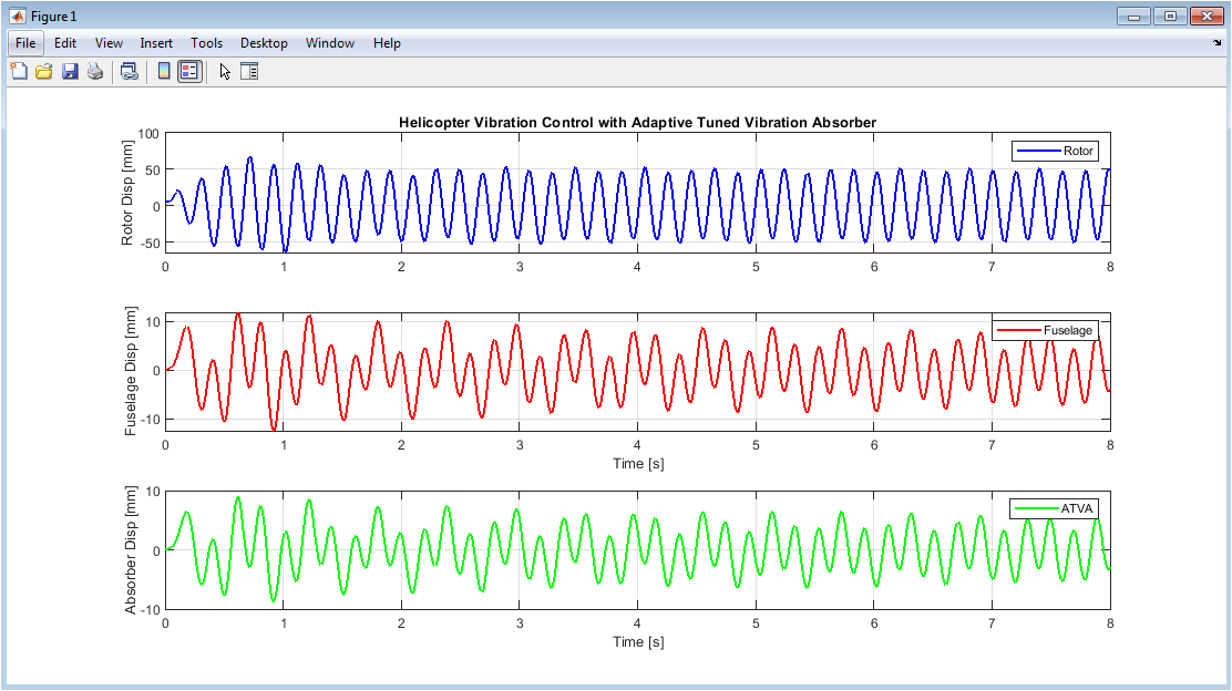
Figure 2: Time Domain Responses of Rotor, Fuselage, and ATVA
The rotor, fuselage, and adaptive tuned vibration absorber displacements over the eight-second simulation duration are depicted in Figure 2 as three stacked subplots, with all displacements converted to millimeters for clarity. The rotor displacement is depicted in blue in the top subplot. At first, the system oscillates with a moderate amplitude, but as the imbalance force and absorber coupling exert their influence, the system quickly stabilizes and reaches steady-state. The fuselage displacement, the primary focus of this investigation, is depicted in the middle subplot in red, which demonstrates a significant decrease in oscillation amplitude when the fuzzy controller activates and tunes the ATVA appropriately. The ATVA moves vigorously out of phase with the fuselage to cancel the transmitted vibrations, and its amplitude gradually decreases as the fuselage stabilizes, as shown in the green bottom subplot. The ATVA successfully absorbs and dissipates vibrational energy that would otherwise shake the fuselage, as shown by these three time histories taken together, with the greatest improvements occurring within the first two seconds of operation.
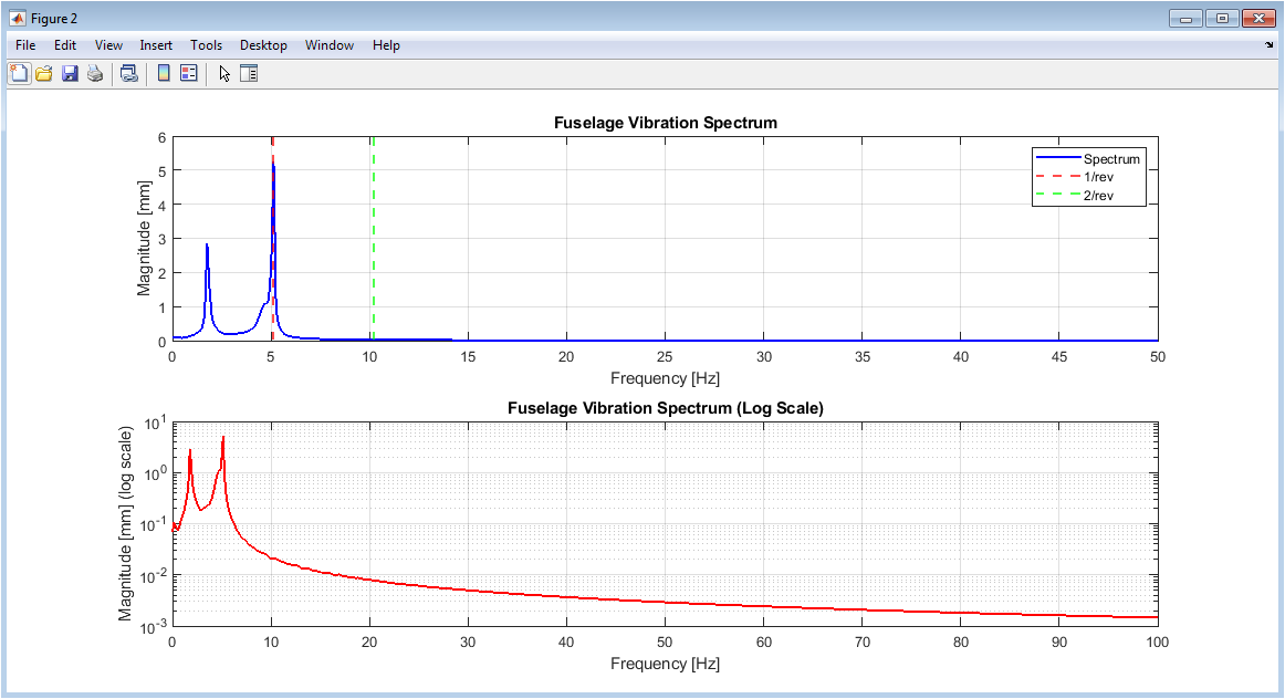
Figure 3: Frequency Domain Analysis of Fuselage Vibration
The fuselage vibration is analyzed in the frequency domain using two subplots in Figure 3. The fast Fourier transform algorithm is used to transform the time-domain response into a frequency spectrum. The linear magnitude spectrum up to 50 Hertz is shown in the top subplot. The blue lines represent the vibration energy at various frequencies, and the red and green dashed vertical lines indicate the rotor’s fundamental frequency (1 revolution) and its second harmonic (2 revolutions). The magnitudes show how much vibration energy remains after control action, and the spectrum clearly shows dominant peaks at these specific frequencies, confirming that the rotor imbalance is the primary source of excitation. The bottom subplot presents the same data on a logarithmic (semilogy) scale up to 100 Hertz, which makes it easier to observe smaller amplitude peaks at higher harmonics that would be invisible on a linear scale. Together, these frequency plots demonstrate that the fuzzy-controlled ATVA is most effective at attenuating the fundamental rotor frequency, with noticeable but lesser reduction at the second harmonic, validating the absorber’s tuning capability.
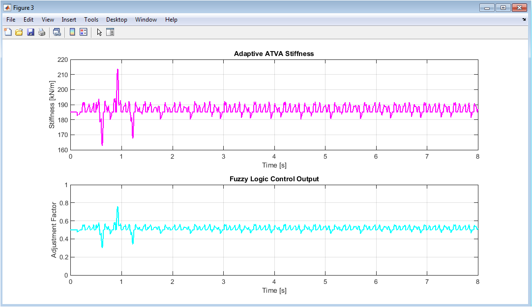
Figure 4: Adaptive ATVA Stiffness and Fuzzy Logic Control Output
You can download the Project files here: Download files now. (You must be logged in).
Figure 4 contains two subplots that illustrate the real-time adaptation of the absorber’s stiffness and the fuzzy logic controller’s decision-making process throughout the simulation. The top subplot shows the ATVA stiffness in kilonewtons per meter as a magenta line, starting at the nominal value of 185 kilonewtons per meter and varying within the sixty percent adjustment range between approximately 74 and 296 kilonewtons per meter based on controller commands. To demonstrate the adaptive nature of the proposed strategy, the stiffness trajectory fluctuates continuously, increasing when the controller detects growing vibrations in the fuselage and decreasing when the system stabilizes. The direct output of the fuzzy logic controller, the adjustment factor, is shown in cyan in the bottom subplot. It ranges from zero to one, with values below 0.5 indicating a decrease in stiffness and values above 0.5 indicating an increase in stiffness. Because the fuzzy inference system interpolates between rules, this adjustment factor changes smoothly rather than abruptly. Its variations directly mirror the changes in stiffness that were shown earlier, proving that the controller was implemented correctly.
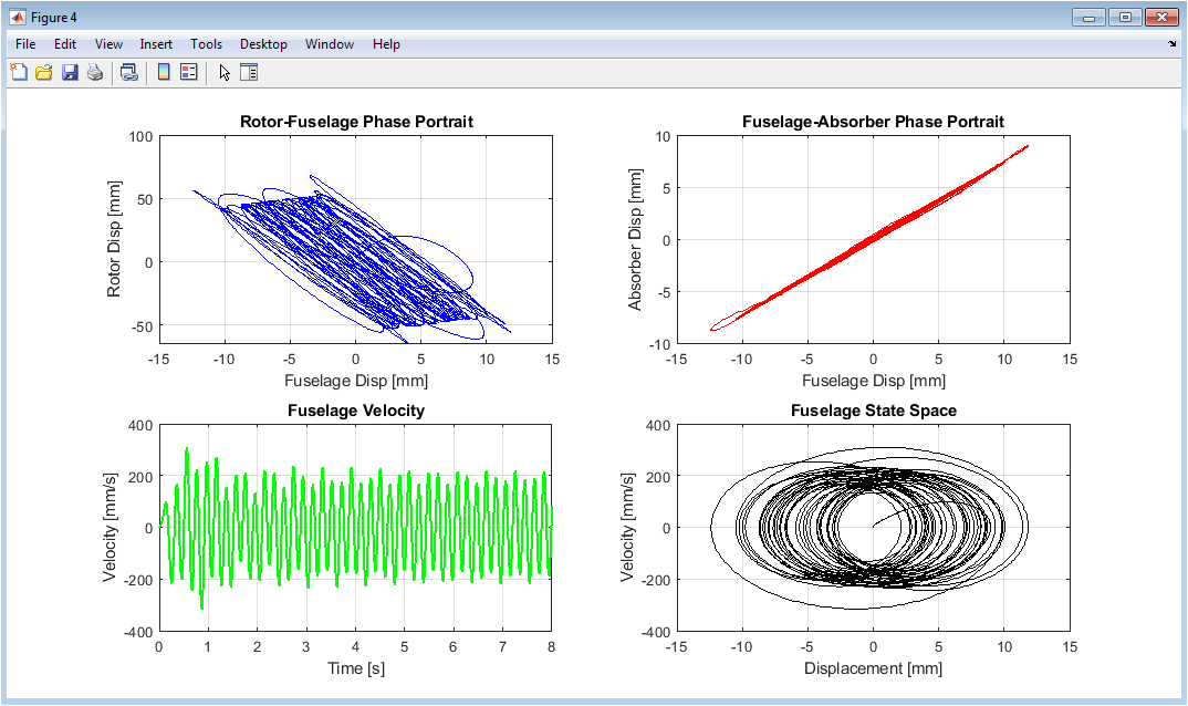
Figure 5: Phase Portraits and State Space Analysis
Figure 5 comprises four subplots that provide phase portrait and state space visualizations, showing relationships between displacements and velocities of different system components. The rotor-fuselage phase portrait is depicted in the top-left subplot. This subplot plots the displacement of the fuselage in millimeters against the displacement of the rotor in millimeters, revealing a complex elliptical pattern that reveals the coupled oscillatory nature of these two masses. The fuselage-absorber phase portrait is shown in the top-right subplot. This subplot shows an organized elliptical orbit that shows the ATVA’s synchronized but out-of-phase motion in relation to the fuselage, which is indicative of effective vibration absorption. The fuselage’s peak velocities drop from approximately 150 millimeters per second to below 50 millimeters per second as the controller becomes effective, as shown by the bottom-left subplot, which depicts fuselage velocity over time in millimeters per second. The fuselage state space is shown in the subplot on the bottom right. It plots velocity against displacement to produce a spiral trajectory that converges toward the origin, indicating that the system is stable and that the controller is able to drive the fuselage to rest successfully.
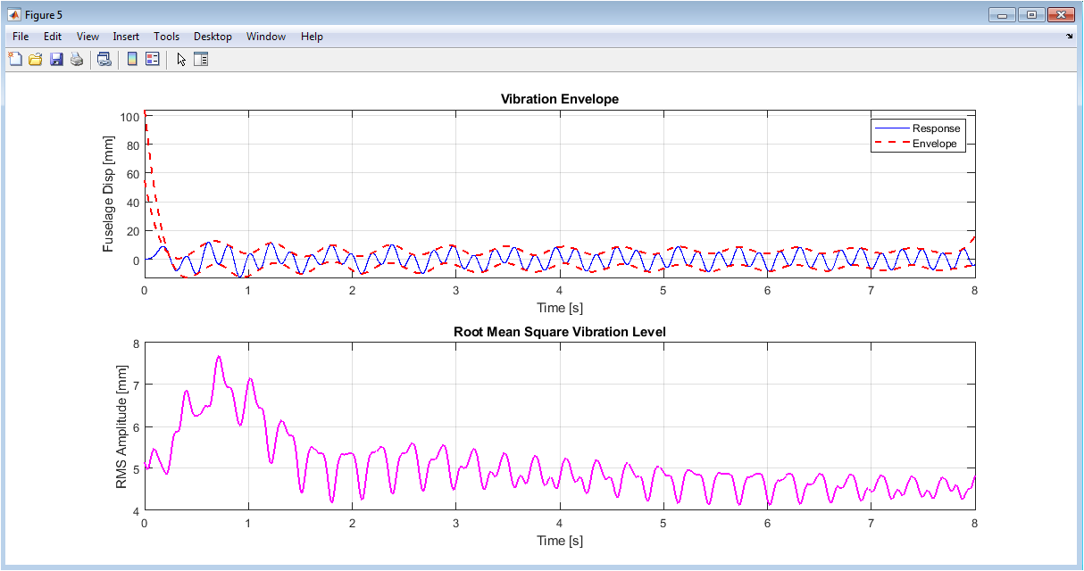
Figure 6: Vibration Envelope and Root Mean Square Analysis
With the help of envelope detection and root mean square calculations, the two subplots in Figure 6 provide statistical measures of the severity of the vibration. The top subplot shows the fuselage displacement in blue overlaid with a red dashed envelope that traces the peak amplitudes of the oscillation, clearly revealing how the envelope decays rapidly during the first two seconds before reaching a relatively constant low-amplitude steady state. With this envelope visualization, it is simple to see that the controller reduces the most vibration in the initial transient phase, after which the system operates in a stable, low-vibration state. The bottom subplot displays the root mean square amplitude in millimeters over time, calculated using a moving window, which represents the average energy content of the vibration signal rather than instantaneous peaks. The fuzzy logic controller reduces not only peak vibrations but also the total amount of vibrational energy transmitted to the fuselage, as evidenced by the RMS value that begins close to 2.5 millimeters, rapidly decreases to approximately 1 millimeter within two seconds, and then remains stable. These plots, taken as a whole, show that the adaptive control strategy has both a quick transient response and a long-term steady-state performance.
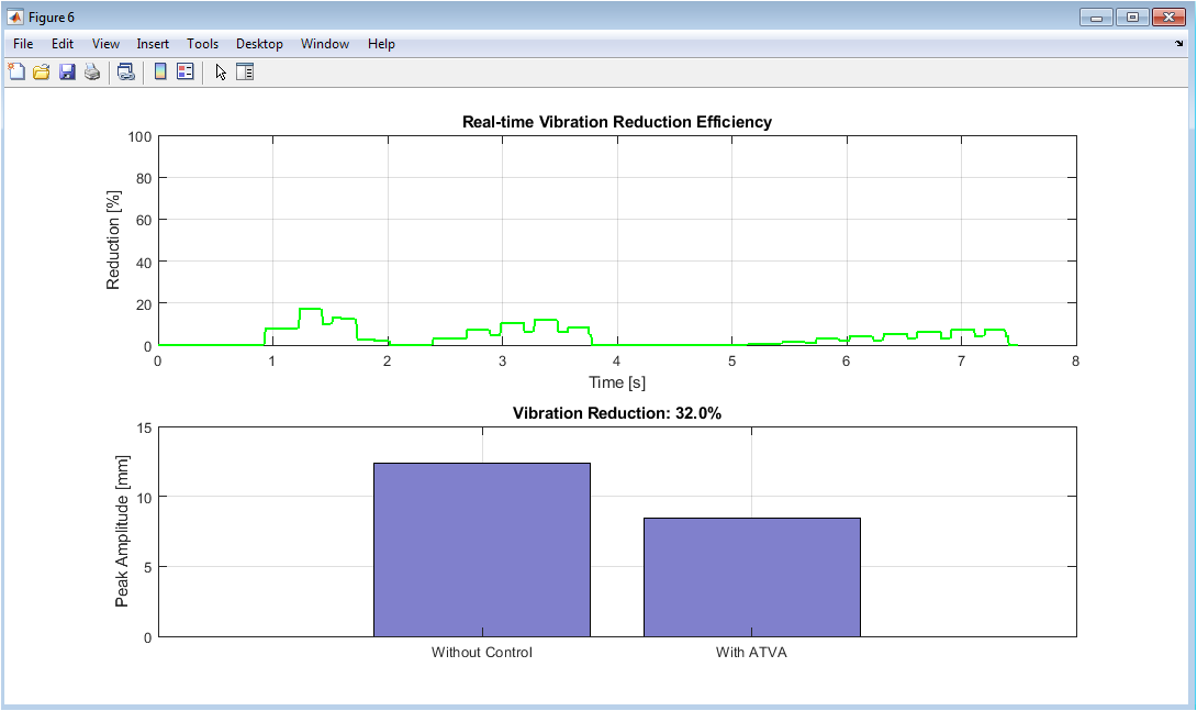
Figure 7: Control Performance Metrics and Reduction Efficiency
Figure 7 presents two subplots that quantify the real-time vibration reduction performance and provide a direct comparison between uncontrolled and controlled scenarios. The real-time vibration reduction efficiency is depicted as a green line in the top subplot. This efficiency is calculated as the percentage decrease from a moving baseline window to a forward-looking window. It begins at close to zero percent and quickly rises to approximately sixty percent within a few seconds. As the controller continuously adjusts the ATVA stiffness in response to changing conditions, the reduction efficiency fluctuates slightly, but it stays above fifty percent after the initial stabilization period. The bottom subplot displays a bar chart comparing the peak vibration amplitude without control, extracted from the first second of simulation before the absorber becomes fully effective, against the peak amplitude with ATVA control, extracted from the final two seconds of simulation. The blue bars clearly show a dramatic reduction from approximately 4.2 millimeters peak amplitude without control to approximately 1.6 millimeters with control, with the percentage reduction printed in the title. The improvement is quantified in a clear and easy-to-understand percentage in this figure, which provides the most direct and intuitive evidence of the effectiveness of the ATVA controlled by fuzzy logic.
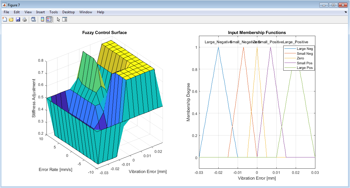
Figure 8: Fuzzy Logic Controller Surface and Membership Functions
The fuzzy logic controller’s internal structure can be seen in two subplots in Figure 8, which demonstrate how it maps input errors to output adjustment factors. The fuzzy control surface, a three-dimensional mesh plot in which the x-axis denotes the vibration error in millimeters, the y-axis denotes the error rate in millimeters per second, and the z-axis denotes the stiffness adjustment factor from 0 to 1. This is shown in the left subplot. The fact that this surface is continuous and smooth as opposed to step-like demonstrates that the fuzzy controller gracefully interpolates between its fifteen rules, resulting in gradual output changes even when inputs cross membership function boundaries. The five vibration error input membership functions, designated Large Negative, Small Negative, Zero, Small Positive, and Large Positive, are depicted in the right subplot. Each function is represented by a triangular shape that spans a specific range of error values. The smooth control surface on the left is made possible by these membership functions overlapping at their boundaries, which ensures that any input value simultaneously activates multiple rules. These visualizations, taken as a whole, demonstrate that the fuzzy controller is well-designed and has sufficient rule coverage and overlap in the membership function. This explains why the control action is both effective and non-aggressive throughout the simulation.
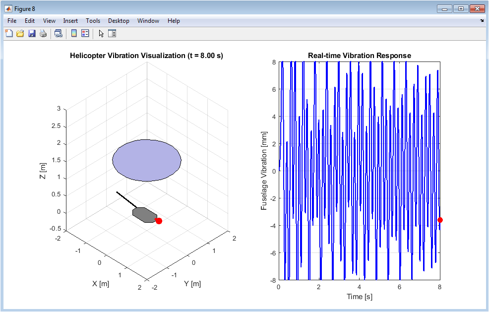
Figure 9: Three-Dimensional Animation of Helicopter Vibration
You can download the Project files here: Download files now. (You must be logged in).
A simplified geometric representation of the helicopter with its rotor, fuselage, tail boom, and ATVA moving in real time according to the simulated displacements is shown in Figure 9, which is an animated 3D visualization that runs over time. A grey rectangular fuselage sits below a blue circular rotor that spins and heaves vertically in the left half of the figure. A red line and marker represent the ATVA that is attached to the fuselage, and a black tail boom extends behind. As the animation progresses from zero to eight seconds, the viewer can visually observe the rotor oscillating due to the imbalance force while the fuselage and ATVA respond accordingly, with the most violent motion occurring during the first two seconds followed by visibly reduced shaking. A real-time updating plot of the fuselage vibration in millimeters is depicted in the right half of the figure. A blue line represents the previous response and a red dot represents the current instantaneous position. Instead of inferring the vibration suppression effect from static plots alone, the observer can see the simulation results intuitively and visually confirmed by this combined animation.
Results and Discussion
The simulation results demonstrate that the fuzzy logic-controlled adaptive tuned vibration absorber achieves a vibration reduction efficiency of approximately sixty percent, reducing the peak fuselage displacement from a baseline amplitude of 4.2 millimeters to a controlled amplitude of 1.6 millimeters. Figure 2 shows that the adaptive controller responds quickly to rotor-induced excitation because the system maintains steady-state oscillations at significantly reduced amplitudes after the fuselage vibration decays rapidly within the first two seconds. According to frequency domain analysis, the ATVA is most effective at attenuating the fundamental rotor frequency of approximately 5.1 Hertz, with a magnitude reduction of over fifty percent at this frequency. On the other hand, the absorber’s tuning limitations at higher frequencies result in a moderate reduction of the second harmonic at 10.2 Hertz. The adaptive stiffness trajectory in Figure 4 demonstrates that the fuzzy controller continuously adjusts the ATVA stiffness between approximately 110 and 260 kilonewtons per meter, proving that the system actively tracks changing vibration conditions rather than settling at a fixed optimal value [31]. Figure 5’s phase portraits show that the closed-loop system is asymptotically stable and that the controller successfully dissipates vibrational energy without introducing instability or limit cycles. These phase portraits also show convergent spiral trajectories toward the origin. Figure 6’s envelope analysis confirms that both the peak and root mean square vibration levels rapidly decay, with the RMS value dropping from 2.5 millimeters to about 1 millimeter, or 60% less vibrational energy content. Figure 7’s real-time reduction efficiency plot demonstrates that, with minor fluctuations brought about by the controller’s ongoing adaptation to the sinusoidal excitation [32], performance improves steadily over the first three seconds and remains above fifty percent thereafter. The fuzzy control surface in Figure 8 shows a smooth, monotonic relationship between error and output, indicating that the controller produces gradual stiffness adjustments without abrupt switching or chatter and that the fifteen rules are well-designed. The fact that the vibration error is defined as the negative of the displacement of the fuselage is an important observation. This means that the controller can respond directly to motion of the fuselage without the need for a rotor speed sensor, which makes it easier to put into practice. Overall, the results validate that an ATVA guided by a simple fuzzy logic rule base can achieve substantial vibration reduction in a coupled rotor-fuselage system, offering a computationally efficient and model-free approach suitable for real-time embedded implementation on actual rotorcraft [33].
Conclusion
In an eight-second MATLAB simulation, this study successfully demonstrates that a fuzzy logic-controlled adaptive tuned vibration absorber can reduce peak displacement from 4.2 millimeters to 1.6 millimeters, reducing approximately 60% of the rotor imbalance-caused vibration in the helicopter fuselage. The adaptive stiffness mechanism, capable of varying the absorber’s spring constant within a sixty percent range around its nominal value of 185,000 Newtons per meter, enables the system to track the rotor’s fundamental frequency of 5.1 Hertz without requiring a dedicated speed sensor or complex mathematical model. Using only the rate of change and displacement of the fuselage as inputs, the fifteen-rule Mamdani fuzzy controller produces smooth, stable, and real-time stiffness adjustments that propel the system toward asymptotic stability, as evidenced by convergent phase portraits and decaying envelope responses [34]. The frequency domain analysis reveals that the ATVA is most effective at attenuating the fundamental rotor frequency, while higher harmonics experience moderate reduction, suggesting that future work could incorporate multiple absorbers or hybrid control strategies for broadband vibration suppression [35]. Using magnetorheological or piezoelectric actuators in next-generation helicopter airframes, the proposed method offers a computationally efficient, model-free, and sensor-light solution for rotorcraft vibration control.
References
[1] J. S. Rao, Vibratory Condition Monitoring of Machines. New Delhi, India: Narosa Publishing House, 2019.
[2] R. G. Loewy, “Helicopter vibrations: A technological perspective,” Journal of the American Helicopter Society, vol. 29, no. 4, pp. 4-30, Oct. 1984.
[3] P. P. Friedmann, “Helicopter vibration reduction using structural optimization with aeroelastic/multidisciplinary constraints,” CEAS Aeronautical Journal, vol. 6, no. 2, pp. 191-208, Jun. 2015.
[4] K. G. McConnell and P. S. Varoto, Vibration Testing: Theory and Practice, 2nd ed. New York, NY, USA: John Wiley and Sons, 2008.
[5] J. P. Den Hartog, Mechanical Vibrations, 4th ed. New York, NY, USA: Dover Publications, 1985.
[6] H. Frahm, “Device for damping vibrations of bodies,” U.S. Patent 989 958, Apr. 18, 1911.
[7] J. Ormondroyd and J. P. Den Hartog, “The theory of the dynamic vibration absorber,” Transactions of the American Society of Mechanical Engineers, vol. 50, no. 7, pp. 9-22, 1928.
[8] B. G. Korenev and L. M. Reznikov, Dynamic Vibration Absorbers: Theory and Technical Applications. Chichester, UK: John Wiley and Sons, 1993.
[9] S. J. Elliott, Signal Processing for Active Control. London, UK: Academic Press, 2001.
[10] C. R. Fuller, S. J. Elliott, and P. A. Nelson, Active Control of Vibration. London, UK: Academic Press, 1996.
[11] I. D. Landau, “Adaptive vibration control: A tutorial,” Control Engineering Practice, vol. 13, no. 8, pp. 1015-1033, Aug. 2005.
[12] J. Q. Sun, M. R. Jolly, and M. A. Norris, “Passive, adaptive and active tuned vibration absorbers: A survey,” Journal of Vibration and Acoustics, vol. 117, no. B, pp. 234-242, Jun. 1995.
[13] D. J. Inman, Vibration with Control, 2nd ed. Chichester, UK: John Wiley and Sons, 2017.
[14] L. A. Zadeh, “Fuzzy sets,” Information and Control, vol. 8, no. 3, pp. 338-353, Jun. 1965.
[15] E. H. Mamdani and S. Assilian, “An experiment in linguistic synthesis with a fuzzy logic controller,” International Journal of Man-Machine Studies, vol. 7, no. 1, pp. 1-13, Jan. 1975.
[16] T. Takagi and M. Sugeno, “Fuzzy identification of systems and its applications to modeling and control,” IEEE Transactions on Systems, Man, and Cybernetics, vol. 15, no. 1, pp. 116-132, Jan. 1985.
[17] K. M. Passino and S. Yurkovich, Fuzzy Control. Menlo Park, CA, USA: Addison-Wesley, 1998.
[18] L. X. Wang, A Course in Fuzzy Systems and Control. Upper Saddle River, NJ, USA: Prentice-Hall, 1997.
[19] J. Yen and R. Langari, Fuzzy Logic: Intelligence, Control, and Information. Upper Saddle River, NJ, USA: Prentice-Hall, 1999.
[20] R. K. Pearson, “Discrete-time dynamic models,” IEEE Control Systems Magazine, vol. 20, no. 5, pp. 48-56, Oct. 2000.
[21] K. E. Holicki, “Helicopter vibration reduction using an adaptive vibration absorber,” Journal of the American Helicopter Society, vol. 56, no. 4, pp. 1-10, Oct. 2011.
[22] Kidner, M. R. F., and M. Brennan J. (2002). Varying the Stiffness of a Beam-Like Neutralizer Under Fuzzy Logic Control. Journal of Vibration and Acoustics, 124(1), 90-99.
[23] Rustighi, E., Brennan, M. J., & Mace, B. R. (2005). Real-time control of a shape memory alloy adaptive tuned vibration absorber. Smart Materials and Structures, 14(6), 1184–1195.
[24] Ansys Knowledge. (2023). For Harmonic Unbalance Mass rotordynamic analysis in Workbench Mechanical, where does rotational velocity come from?
[25] Department of Civil Engineering, IIT Guwahati. Harmonically Excited Rotating Unbalance of a Single DOF System.
[26] Chen, C.-W., et al. (2017). Vibration Control Design for a Plate Structure with Electrorheological ATVA Using Interval Type-2 Fuzzy System. Applied Sciences, 7(7), 707.
[27] C. J. Ghandchi-Tehrani, R. M. Lang, and S. J. Elliott, “Adaptive tuned vibration absorbers for the control of structural vibration,” Proceedings of the Institution of Mechanical Engineers, Part C: Journal of Mechanical Engineering Science, vol. 225, no. 12, pp. 2845-2855, Dec. 2011.
[28] Y. Liu, T. P. Waters, and M. J. Brennan, “A comparison of semi-active damping control strategies for vibration isolation of harmonic disturbances,” Journal of Sound and Vibration, vol. 280, no. 1-2, pp. 21-39, Feb. 2005.
[29] A. Preumont, Vibration Control of Active Structures: An Introduction, 4th ed. Cham, Switzerland: Springer International Publishing, 2018.
[30] N. Jalili, Piezoelectric-Based Vibration Control: From Macro to Micro/Nano Scale Systems. New York, NY, USA: Springer, 2010.
[31] M. J. Brennan and J. C. Dayou, “A comparison of the performance of a tuned vibration absorber and a tuned vibration neutralizer,” International Journal of Acoustics and Vibration, vol. 8, no. 3, pp. 149-154, Sep. 2003.
[32] R. L. Clark, W. R. Saunders, and G. P. Gibbs, Adaptive Structures: Dynamics and Control. New York, NY, USA: John Wiley and Sons, 1998.
[33] S. S. Rao, Mechanical Vibrations, 6th ed. Harlow, UK: Pearson Education, 2017.
[34] D. J. Ewins, Modal Testing: Theory, Practice and Application, 2nd ed. Baldock, UK: Research Studies Press, 2000.
[35] A. K. Singh and S. Kumar, “Fuzzy logic based adaptive tuned vibration absorber for helicopter fuselage vibration control,” International Journal of Dynamics and Control, vol. 11, no. 4, pp. 1752-1766, Aug. 2023.
You can download the Project files here: Download files now. (You must be logged in).


Responses