Matlab and Simulink – a must-have tool for signal processing
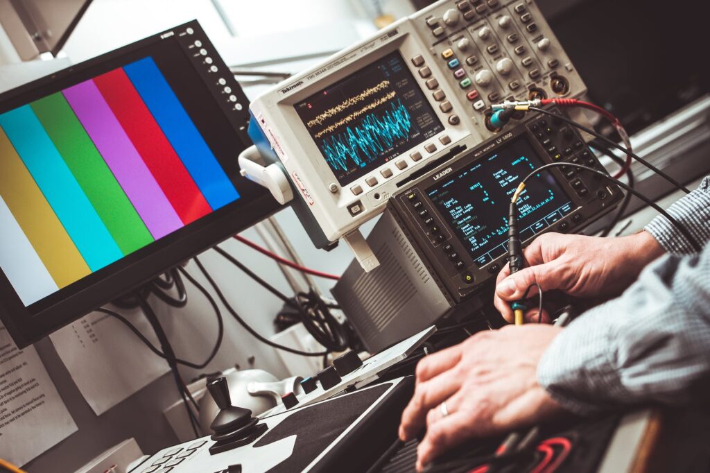
With its first introduction in 1984, MATLAB quickly became a sensation in the scientific community. Since then, it is being effectively used in the area of signal processing systems, automotive, finance, and many other fields. It has now been considered a de facto standard for all engineers and scientists for their simulations and developments. In this article, we particularly will have a close look at Matlab Simulink for signal processing purposes.

The Monopoly of Matlab
The liberty provides to the user is simply unmatchable. Although this area of numerical computing has rapidly evolved and various software suits exist today, however, there has not been a true competitor in the area of signal processing algorithm design and development. Initially, starting as a simulation-only environment, it evolved gradually and encompassed various other areas in itself. To date, hardware support has been added whereas code generation for deployment has been supported well.
Features like cloud connection and computing have also long been there. Additionally, multiprocessor execution and Parallel computing have been added. Moreover, verification and validation methodologies have been incorporated according to contemporary industry standards, to make it more productive for engineering and scientific computing. Broadening its spectrum and incorporating so much within its environment has allowed MathWorks to keep its leading place in the ever-changing global market. MathWorks can indeed be seen as the one with a time-proven strategy to uphold the top position as a top signal processing development and deployment environment.
Simulink – the Evolution to Model-Based Design
Matlab gradually adopted its environment from a script-only to a visual programming environment formally called as Model-Based Design. This add-on, called Simulink is now one of the most successful products of MathWorks and has created a new paradigm in the industry. The complex signal processing and control algorithms which used to be completed in months can now be developed within a few hours and can be deployed over the hardware of choice with absolute confidence. This whole end-end development methodology also called full-cyle development, is unprecedented. Now the designer can focus more on the accuracy and features within its algorithm, rather than spending valuable time debugging the codes. As a result, this has greatly enabled the development teams and increased their productivity manifold.

How Matlab Streamlines Development Teams
A few decades ago, the team size for product development was considered to be quite large, with specialized tasks assigned to each sub-group. As an example, algorithm design was a specialized field, its translation was done by another team and its deployment and hardware-associated features were done by some other team members. All of these people worked together coherently to achieve the final goal of product development.
Over time, much smaller teams with numbers in a single digit are seen, where support for automated tools has been maximized to reduce the time and HR dependency. Hence reducing the risks and great reduction in time to market and bugs in the development cycle. Testing and verification have become an integral part of the development now and complete conformance and validation to achieve a zero-bug level are now achievable through integrated quality tools like polyspace. An engineer can now use automated code generation to generate the production code with all the features asked for and easily conform his code to the industry standards. All of this adds up for a larger benefit and greatly makes the timely delivery of the product to market possible with a much smaller company size than before.
Scripting vs. Visual Programming
If we segregate MATLAB based on the programming methodology, then it can safely be divided into two major programming environments. The first one is scripting and the other one is the visual programming method also called as Model-Based Design. MATLAB itself uses scripting, whereas Simulink (an environment inside Matlab) focuses on Model-Based Design. Both environments have their power. As time has passed and version releases newer features are being incorporated into the programming suite. Scripting environment provides users with the ease to code, who have prior knowledge of any other language. Being at a higher abstraction level, coding is quite easier and more human-friendly. This can be taken further and taken towards implementation.
For implementation, two major pathways exist, i.e. a processor deployment and the FPGA deployment. The Matlab script can be translated into C/C++ code which is human readable or Verilog/VHDL code which gets synthesized as hardware and goes inside an FPGA. Optimized code generation is supported for numerous platforms; some of these are TI DSP, Analog Devices DSP, NXP Microcontrollers, STM Microcontrollers, Siemens PLCs, and many more. The library of supporting hardware is ever-growing with each release and a detailed listing can be found on their website.
Adapting to New Technologies
Matlab is also adapting to development in the field and has recently given apps to support the topics like AI, Deep Learning, Big Data, and even programming FPV drones is not alien to Matlab anymore. Industrial automation which relies on the PLC can benefit from the product and devise a control using state flow. The Stateflow uses visual diagrams with blocks and arrows to define complete control flow. With so many options and so many features, Matlab is no more just another tool to be learned. It solves your issues, provides you with features and tool to reach answers, and save a tremendous amount of time for simulation and development.
The Power of MATLAB for Signal Processing
Probably the best-suited tool for signal processing in modern times, it can do miracles and make things work very well. As an example, optimized filter design with support for various architectures is built in. Discretization of the continuous system, non-linear parameter estimation, linearization of a nonlinear system, audio analysis and processing, 2D image processing, and much more is available. Not only it all can be simulated but all the steps of product development are tightly integrated into this environment to which no other tool can match up. The full cycle of simulation – deployment – verification and quality conformance is built in and allows a user to pass through all of it and produce a well-tested quality code, which reduces the design iteration to its minimum.

Keeping Up with the Latest Hardware
MATLAB is rapidly incorporating new processes and new hardware to keep up to date. You can easily find the newest processors in the library and can make well use of them. Every new release is adding up new functions and blocks and empowers the product designers more and more. Toolboxes are like libraries that add up to the power and provide built-in functions and blocks. These function or blocks implements simple to complex algorithms and enables the use of these in a larger system.
As an example, you can find a PID controller block in Simulink and can use the apps provided to tune the gains on your desk. With similar ease, if you need to make an audio filter you can use among the various filter block architectures provided in the toolboxes and tune its parameters to suit your requirement. Now if you are required to take it further on some microcontroller, you can generate a C/C++ code from these and port it over the hardware. Similarly, if you want to port it to FPGA, you can generate the code and port over the FPGA of your choice.
An amazing thing, this development methodology provides to the engineers is the future-proofing of their design. Obsolescence of a certain processor doesn’t hamper your product anymore; simply change the processor and you are good to go. In short, your algorithm stays there, and the design effort conducted earlier is saved.

Conclusion: The Ideal Tool for Signal Processing
For signal processing applications there is no better environment than MATLAB. With the selection of the right toolbox, addons, and the support provided on the MathWorks website. The answer to nearly every problem of signal processing can be sought. Time-frequency analysis, curve fitting, distribution fitting, filtering visualization, and much much more are available at the click of a button. It all depends on your style of coding. Whether you want to stay at the higher abstraction layer or want to dive deep down where drivers can be made to interact with external hardware. All of this is possible within MATLAB. In short, it is a must-have tool for any engineer in the field of signal processing.
Solving Signal Processing Problems with WiredWhite
We have the expertise to work and develop the solution to your problem. Having various experts on our panel, who have worked in the industry and competitive ability to create the solution, is what you can rely on. You can initiate your project on the portal, and we will guide you through the process through our trained team members. The scale of the project doesn’t matter. We have experts specialized in complementary areas, who can provide you with the solution you require.
Please note, we are not like any other freelancing website, which has become so inconvenient. Our experts focus on engineering. The task assigned by you are guaranteed to be completed, up to your satisfaction level. You can try and feel the difference yourself. So, please move forward by joining the portal and launching a project to gain your confidence.
If you have any doubts or facing any problems, please do not hesitate to give WiredWhite a message.





Responses