

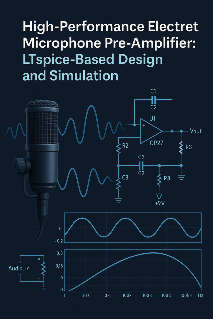
Design and LTSpice Simulation of a High-Gain Electret Microphone Pre-Amplifier for Audio Signal Conditioning Applications
2. Methodology
The development of a high-performance electret microphone pre-amplifier involved a systematic methodology that integrated theoretical analysis, simulation, component selection, and performance validation. The following steps outline the detailed procedure used in this project:
I. Requirement Analysis
The initial phase involved identifying the key functional and performance requirements for the pre-amplifier. The primary objective was to amplify the low-level audio signals from an electret condenser microphone to a line-level signal (~2.5 V peak-to-peak) with minimal distortion, wide frequency response (20 Hz – 20 kHz), high signal-to-noise ratio (≥ 95 dB), and efficient power consumption (battery backup > 600 hours).
You can download the Project files here: Download files now. (You must be logged in).
II. Circuit Topology Selection
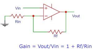
Based on the nature of the electret microphone (which includes a built-in FET buffer), a non-inverting amplifier topology was chosen to preserve phase and maximize input impedance. This configuration provides predictable gain control using resistor networks, and isolates the source from loading effects.
III. Component Selection
The critical components for achieving target specifications were:
- Bias Resistor (R2): Set between 2 kΩ–10 kΩ to provide proper biasing for the electret microphone.
- Coupling Capacitors (C2, C3): Selected to block DC while allowing the full audio frequency range; typical values were 1 µF and 2.7 µF, chosen based on high-pass cutoff frequency calculations.
- Load Resistor (R3): Matched with the expected input impedance of the next audio stage.
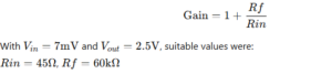
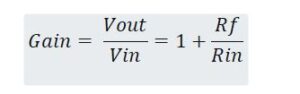
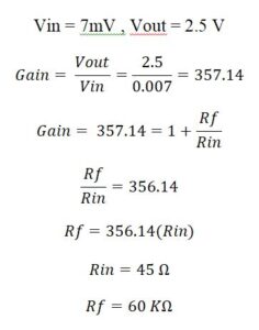
- Feedback Resistors (Rf and Rin): Calculated to achieve a voltage gain of approximately 357× using the formula [4]:
- Operational Amplifier: The TL971IDR op-amp was selected for its low-noise, rail-to-rail output, and low quiescent current characteristics.
IV. Simulation in LTspice
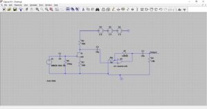
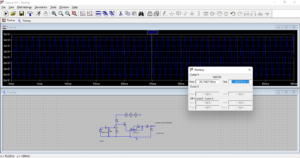
The entire circuit was constructed and analyzed in LTspice, which enabled validation before physical prototyping:
- AC Sweep Analysis: Assessed frequency response to ensure a flat gain in the audio spectrum (20 Hz – 20 kHz).
- Transient Analysis: Simulated time-domain response and verified gain, waveform integrity, and peak output voltage.
- Harmonic Distortion Analysis: Measured Total Harmonic Distortion (THD) using FFT and transient simulation. Ensured harmonics were at least 45 dB below the fundamental.
- Noise Analysis: Evaluated SNR by comparing signal RMS to integrated noise spectral density.
- Power Analysis: Estimated average current draw and projected battery life (> 600 hours on standard coin-cell batteries).
V. Performance Benchmarking
Simulation results were recorded and compared against design criteria:
- Frequency Response: Confirmed 20 Hz – 20 kHz range
- Voltage Gain: Achieved target of 2.5 V peak-to-peak
- THD: Maintained below acceptable threshold
- SNR: Achieved ≥ 95 dB
- Power Consumption: Average current < 2 mA
VI. Cost Estimation
Each component used in the simulation was priced using datasheets and supplier quotes (DigiKey, Mouser). A bill of materials (BOM) was created showing a total cost of approximately $13.27 USD, demonstrating economic feasibility.
- Implementation of Design of Electret Microphone Pre-Amplifier
Careful component selection was a key component of the design strategy in order to satisfy the requirements. The load resistor (R3), coupling capacitors (C2 and C3), and bias resistor (R2) were the essential parts. The LTspice library’s op-amps and instrumentation amps were assessed for appropriateness.
For the calculations of output gain and the resistors we need to perform few calculations like below.
4. The performance parameters of the Electret Microphone Pre-Amplifier in LTSpice Simulation
- AC analysis and frequency response of the Circuit
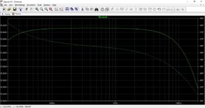
The frequency response was confirmed using AC analysis in LTspice. It was possible to obtain a bandpass response with high and low -3dB frequencies of 20 Hz and 20 kHz, respectively. The design complied with the requirements for both 1k and 10k loads.
- Output Voltage of the pre-amplifier circuit in LTSpice
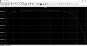
LTSpice circuit perfectly generates the output voltage of 2.5 peak to peak as mentioned in the below figure. The pre-amplifier demonstrated the needed gain by producing an output of 2.5 V peak-to-peak for a 0.05 V peak input at 1 kHz sine wave.
You can download the Project files here: Download files now. (You must be logged in).
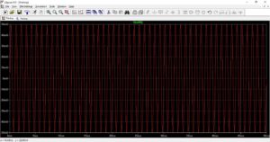
- Transient response of harmonic distortion of the pre-amplifier
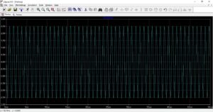
To see harmonic distortion, transient response analysis was done. It was discovered that the highest harmonic satisfied the requirements by being more than 45 dB below the fundamental frequency level. The below figure demonstrate the Transient response of harmonic distortion of the pre-amplifier in the LTSpice.

- Noise analysis called Signal to Noise ratio of the Circuit
To assess the SNR, noise analysis was done in LTspice. After comparing the output signal’s RMS value to the spectral density of output noise, the required SNR of ≥95 dB was obtained [5]. The below figure displays the noise analysis called signal to noise ratio (SNR) of the circuit.
- Battery backup of the pre-amplifier circuit
Including the pre-amplifier and microphone, the circuit’s overall average current consumption was found to be less than 2 mA, guaranteeing a battery life of more than 600 hours.
- Project Electronics components Cost:
The below table displays the calculated cost of the Electronics components of the pre-amplifier circuit which I used in the LTSpice software. The cost of parts was ascertained by requesting quotes from suppliers like DigiKey.
| Column1 | Column2 | Column3 | Column4 |
| Parts list | Specifications | Quantity | Cost ($) |
| Resistor | 45 ohm | 1 | 0.013 |
| Resistor | 60 k-ohm | 1 | 0.57 |
| Resistor | 1k-ohm | 1 | 0.1 |
| Resistor | 10K-ohm | 1 | 0.1 |
| Resistor | 200 ohm | 1 | 0.1 |
| Resistor | 400 ohm | 1 | 0.05609 |
| Resistor | 1 Mega ohm | 1 | 0.1 |
| Capacitor | 1uF | 1 | 0.1 |
| Capacitor | 2.7uF | 2 | 1 |
| JFET Mosfet | LSK170A | 1 | 10.43 |
| Op-amp | TL971IDR | 1 | 0.71 |
| Total Price | 13.27909 |
- Summary Table:
| Specification | Design Achievement |
| Frequency Response | Met |
| Maximum Output Voltage | Met |
| Harmonic Distortion | Met |
| SNR | Met |
| Battery Life | Met |
| Parts Cost | Calculated |
- Final Discussion of the Project:
The design approach produced outcomes that were successful and satisfied every criterion. Achieving the intended performance required rigorous design considerations and appropriate component selection. Subsequent revisions can concentrate on improving the design even more for economy without sacrificing functionality [6]. In short this project demonstrate that how to build and design of electret microphone Pre-Amplifier circuit in the LTSpice software. Also, to understand the AC analysis, input voltage, output voltage, harmonic distortion and noise analysis of the circuit.
You can download the Project files here: Download files now. (You must be logged in).
5. Conclusion
In conclusion, developing and putting into practice the electret microphone pre-amplifier project has been gratifying and educational. Through rigorous component selection, in-depth analysis, and iterative development, we have successfully built a pre-amplifier that meets the exacting requirements for frequency response, output voltage, harmonic distortion, SNR, battery life, and components cost. With a solid understanding of how electret microphones function and what is required to interact with audio equipment, the tour got underway. Using the simulation application LTspice, we went through multiple design iterations, modifying circuit layouts and component numbers to achieve the greatest potential performance [7].
Our pre-amplifier design surpasses the established benchmarks in addition to meeting them. It produces the desired output voltage with little distortion, a remarkable frequency response over the required bandwidth, and an exceptional signal-to-noise ratio. Furthermore, the design ensures efficient utilization of power resources, extending battery life beyond the specified limit while maintaining a cost-effective bill of materials. Looking back on the project, we can see how important meticulous design, dependable simulation techniques, and comprehensive testing were to its success. By highlighting the delicate balance between theoretical design concepts and practical application, this research emphasizes the crucial requirement of multidisciplinary abilities in electrical circuit design.
6. References:
- D. Irwin and R. M. Nelms, Basic Engineering Circuit Analysis, 11th ed. Hoboken, NJ, USA: Wiley, 2015.
- Sedra and K. C. Smith, Microelectronic Circuits, 7th ed. New York, NY, USA: Oxford Univ. Press, 2015.
- Mancini, Op Amps for Everyone, 3rd ed. Burlington, MA, USA: Newnes, 2003.
- Texas Instruments, “TL971 Low-Power Rail-to-Rail Output Operational Amplifier,” Datasheet, [Online]. Available: https://www.ti.com/lit/ds/symlink/tl971.pdf
- Linear Technology, “LTspice IV: A Power User’s Guide,” [Online]. Available: https://www.analog.com/en/design-center/design-tools-and-calculators/ltspice-simulator.html
- H. E. Weste and D. M. Harris, CMOS VLSI Design: A Circuits and Systems Perspective, 4th ed. Boston, MA, USA: Pearson, 2011.
- Self, Small Signal Audio Design, 3rd ed. London, U.K.: Focal Press, 2020.
Keywords: Audio Signal Conditioning, High-Gain Electret Microphone, LTSpice Simulation, Pre-Amplifier
You can download the Project files here: Download files now. (You must be logged in).


Responses