

Design and Simulation of a Vending Machine in Logisim-Evolution

Abstract
This project presents the design, implementation, and simulation of a vending machine circuit using Logisim-Evolution. The goal is to model a real-world vending machine capable of accepting coins, dispensing products, returning change, and tracking product inventory. Using only combinational logic and simple sequential circuits, the simulation meets specific functional requirements, such as accepting 5, 10, and 25 cent coins, disabling input after 75 cents, restocking items, and maintaining a total money register. The simulation validates the logical design and control flow of a vending system in a digital circuit framework [1]. The complete design is tested for accuracy, reliability, and adherence to constraints, with necessary corrections applied to resolve logic flaws.
Introduction
Vending machines are real-world electromechanical systems that require digital logic for their operation. These systems handle various inputs such as coin recognition, product selection, and stock tracking, and produce outputs including product dispensing, change return, and status indication [2]. In this project, Logisim-Evolution is employed to simulate a vending machine with limited product types and specific constraints on coin inputs and operational behavior. This simulation allows circuit behavior to be tested and analyzed before any physical implementation [3].
The purpose of this report is to present the systematic design, simulation, and analysis of a digital vending machine. Key learning objectives include the integration of combinational and sequential circuits, handling input conditions, decision-making based on control signals, and circuit-level problem solving [4]. The project also identifies and corrects three key design flaws in the initial configuration, ensuring that the final simulation meets all functional specifications.
Design Methodology
The vending machine system is composed of multiple interconnected subcircuits, each performing a distinct function. These include:
- Main Circuit: Interface between users and the internal logic.
- Bank Subcircuit: Accumulates coin values and outputs total deposit.
- Activator Subcircuit: Compares deposit value to 75 cents and computes change.
- Dispenser Subcircuit: Controls the selection and dispensing of products.
- Product Subcircuits: Maintain count of items and manage inventory.
- Vending Subcircuit: Integrates all other modules.
The design follows a modular approach, allowing for independent testing and debugging of each unit. A combination of logic gates, multiplexers, decoders, comparators, counters, and basic input/output components is used to model realistic behavior [5].
You can download the Project files here: Download files now. (You must be logged in).
3. Logisim Simulation Design Work and Results
Coin Detection and Input Circuit:
This circuit was designed to detect and accumulate the coin inputs (Rs. 5, Rs. 10). In Logisim, input buttons were used to represent coin insertions. These inputs were connected to an adder circuit using binary encoders to represent the coin value in binary. A clock signal was used to store the cumulative coin value using a register [6]. The main components used were input pins, adders, binary constants, and registers. The adder continuously updated the total inserted amount, displayed using a hexadecimal display.
Product Selection and Control Circuit:
This part of the vending machine was responsible for taking product selection and checking if the inserted amount matched the product cost. Input pins were used to represent the selection of Product A (Rs. 10) or Product B (Rs. 15). A comparator was used to compare the inserted amount against the cost of the selected product. If the condition was met, an enable signal was generated. Components used included multiplexers (for product selection), comparators (to check sufficient balance), constants (product prices), and logic gates to generate enable signals for dispensing.
Dispensing Circuit:
This circuit activated the dispensing mechanism when the selection and sufficient balance conditions were fulfilled. Once the product enable signal was generated, it triggered a clocked register or D flip-flop to create a short active pulse for the motor/actuator (represented using an output pin in Logisim) [7]. The output pin was connected to an LED or a label to represent successful dispensing. The components used were output pins, D flip-flops, and AND gates.
Change Return Circuit:
After product dispensing, the leftover balance (if any) was calculated and returned as change. Subtractor circuits were used to determine the remaining amount by subtracting product cost from the inserted amount. This remaining value was routed to an output display or LED-based circuit to represent the change. Registers were used to hold and transfer data, while control logic managed the timing of the change return signal. Components used included subtractors, registers, constants, output pins, and AND gates.
System Reset and Control Logic:
To ensure reliable operation, a reset mechanism was implemented to reset the registers and counters after each transaction. A reset push-button input was connected to a synchronous reset line for all key components. Additionally, control logic ensured the sequential operation of insert–select–dispense–reset. This was done using control gates and clock signals. Components included input pins, logic gates (AND, OR, NOT), and synchronous clear inputs on registers.
Each circuit was developed using a modular approach in Logisim. Blocks were tested individually, and connections were made using tunnels and wires for readability. Labels were added to ensure the clarity of signal paths and data flow.
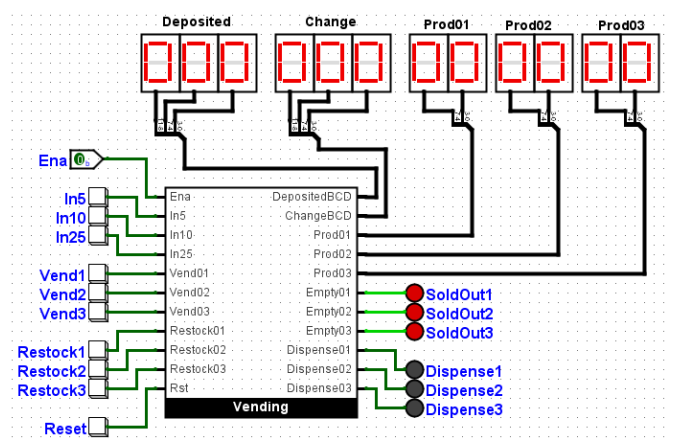
3.1 Main Circuit
The main circuit simulates the user interface of the vending machine. It includes inputs for enabling/disabling the machine, depositing coins (In5, In10, In25), selecting products (Vend1, Vend2, Vend3), restocking (Restock1, Restock2, Restock3), and resetting the deposit. Numeric displays show the total amount deposited, returned change, and inventory levels. LED indicators signal sold-out products and dispense events.
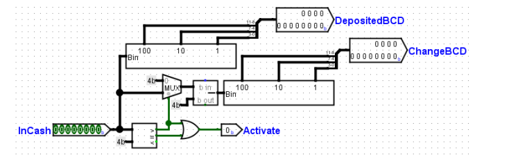
3.2 Activator Subcircuit
The Activator converts the binary deposit value to BCD for display and compares it to 75 cents. If the value is greater than or equal to 75, the Activate signal is set high to enable product dispensing [8]. Excess amount is calculated by subtracting 75 and is output as ChangeBCD. This subcircuit directly controls the Dispenser’s access to product vending logic.
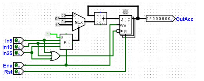
3.3 Bank Subcircuit
The Bank subcircuit processes the deposited coins. Inputs (In5, In10, In25) are encoded via a priority encoder and passed to a mux-controlled adder. The total is stored in a register with feedback to allow cumulative addition. A three-input OR gate drives the clock signal to the register, ensuring the value updates with each coin. Edge-triggering guarantees correct timing. Output is the accumulated deposit sent to the Activator.
You can download the Project files here: Download files now. (You must be logged in).
3.4 Dispenser Subcircuit
This logic block handles product dispensing. Based on user selection and the Activate signal, a demux routes the signal to the appropriate Product subcircuit. If Activate is low, the demux passes zeros, disabling any dispensing. LEDs and inventory counters reflect successful vends and track remaining stock [9].
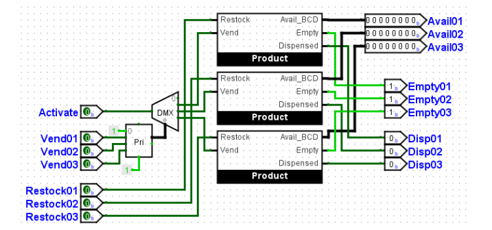
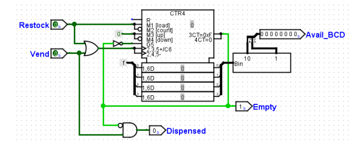
3.5 Product Subcircuits
Each product type has a dedicated subcircuit with a counter preset to 15. Vend input triggers a decrement operation, reducing available items by one. Restock input resets the counter to full stock. Binary counts are converted to BCD for display. A zero count sets the Empty flag, illuminating the Sold Out LED.
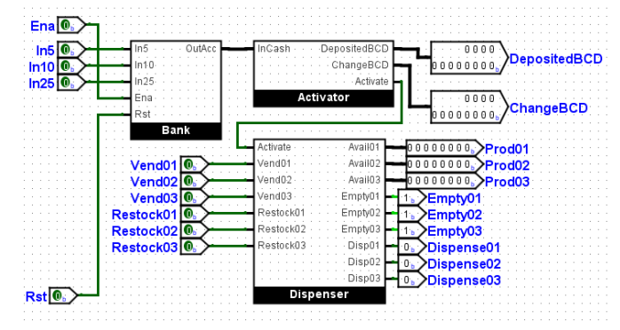
3.6 Vending Subcircuit
This is a wrapper module encapsulating the Bank, Activator, Dispenser, and Product blocks. It serves as a reusable logic unit instantiated in the main circuit. No additional logic is added here.
3.7 Testing and Observations
To verify functionality:
- Ena is enabled and SoldOut LEDs initially indicate empty products.
- Restocking buttons refill inventory and extinguish SoldOut indicators.
- Coins are inserted, total displayed, and any excess reflected as change.
- Once 75 cents is reached, Vend buttons allow product dispensing.
- If 75 cents isn’t reached or a product is sold out, the selection is ignored.
3.8 Identified Flaws and Corrections
Three flaws were observed in the initial implementation:
- Coins Accepted Beyond 75 Cents: Coin input logic was modified to disable further accumulation once total reaches 75.
- Deposited and Change Amount Not Reset After Vend: Reset signals were added post-dispensing to clear deposits and change.
- Total Collected Amount Not Tracked: A new counter/register combination was added to store each 75-cent transaction and accumulate total money collected by the machine [10].
After implementing these fixes, the system behaved as intended under all test cases.
You can download the Project files here: Download files now. (You must be logged in).
Conclusion
The vending machine simulation designed using Logisim-Evolution demonstrates how digital logic can model real-world systems. Modular subcircuits enabled a clear design flow, allowing for easier debugging and modification. Corrections to logical flaws ensured that system constraints were respected, such as coin limit enforcement, change return, and transaction reset after purchase.
The final design accurately simulates customer interaction, stock management, and transaction logging. It also emphasizes the importance of thorough testing in digital design. Such projects prepare students for advanced hardware system design by reinforcing concepts in state machines, arithmetic logic, and combinational circuits. Future enhancements could include LCD simulation, price variability, and support for more products or payment methods.
References
- Logisim-Evolution Documentation – https://github.com/reds-heig/logisim-evolution
- Brown, S., & Vranesic, Z. (2013). Fundamentals of Digital Logic with VHDL Design. McGraw-Hill.
- Mano, M. M., & Ciletti, M. D. (2017). Digital Design. Pearson.
- Harris, D., & Harris, S. (2012). Digital Design and Computer Architecture. Morgan Kaufmann.
- Wakerly, J. F. (2006). Digital Design: Principles and Practices. Prentice Hall.
- Bhattacharya, A. (2020). Digital Logic Design. Oxford University Press.
- Floyd, T. L. (2013). Digital Fundamentals. Pearson.
- Katz, R. H., & Borriello, G. (2004). Contemporary Logic Design. Prentice Hall.
- IEEE Digital System Design Standards
- Online tutorials and community forums for Logisim-Evolution.
You can download the Project files here: Download files now. (You must be logged in).


Responses