

Industrial Automation of BMC Machine Using PLC Control System
Author: Waqas Javaid
Introduction
I developed the industrial automation of a BMC (Bio-Medical Component) machine for SENSOMEDICAL, focusing on integrating advanced motion control with precise mechanical positioning to enhance accuracy, repeatability, and operational efficiency. The BMC machine in this project was originally a semi-automated mechanical system, and my task was to design, implement, and commission a complete PLC-controlled automation solution that could be directly attached to the existing machine structure without requiring major mechanical redesigns. This automation aimed to control two primary mechanical subsystems: the upper circular track, responsible for rotational motion, and the outer vertical moving mechanism, responsible for precise linear movement. In addition to the core mechanical automation,
I integrated a fully functional PC interface through an Ethernet connection, enabling operators to configure, monitor, and control the machine in real-time from a graphical or command-line environment. The key parameters—acceleration, position, and velocity—were made configurable by the operator, with all adjustments and commands logged in the system event log for traceability and compliance. My development approach emphasized reliability, safety, and precision, as the BMC machine is used in sensitive manufacturing operations that require consistent performance over long operational cycles [1].
Project Background
When I began this project, the BMC machine was being operated manually, which limited its speed, repeatability, and operational efficiency. Manual control often introduced human error, resulting in inconsistent product quality and increased wear on mechanical components due to uncontrolled acceleration or abrupt stops. The need for automation was evident to meet both production demands and quality assurance requirements. I selected a PLC-based control architecture because PLCs are robust, reliable, and widely used in industrial automation, making them ideal for environments where machine downtime must be minimized [2]. Additionally, PLCs offer flexible programming, easy integration with sensors and actuators, and support for industrial communication protocols such as Ethernet/IP and Modbus TCP, which are essential for linking the control system to the PC-based interface. The core of the automation system was to control the upper circular track with a maximum rotational speed of 150 rpm and a resolution of 0.1 degrees, as well as the outer vertical moving mechanism with a stroke of 500 mm, maximum speed of 500 mm/s, and load capacity of 80 N. The design goal was to ensure smooth acceleration and deceleration to prevent mechanical stress and to integrate position feedback systems for accurate motion control.
Machine Overview and Specifications
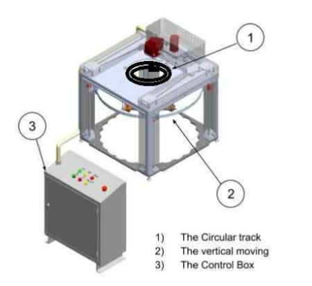
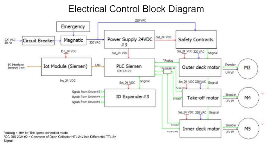
The BMC machine consisted of three main sections: the circular track (upper rotating section), the outer vertical moving mechanism, and the control box. The circular track allowed precise rotational positioning of the attached tooling or workpiece, enabling processing at different angular positions without manual repositioning.
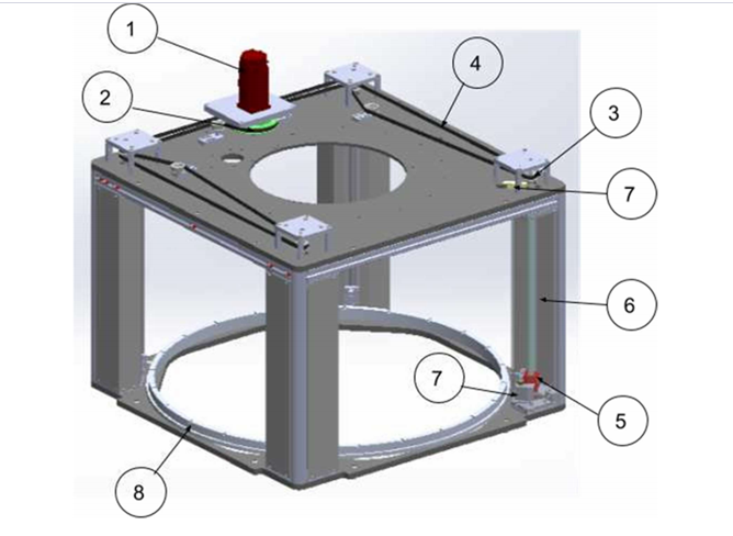
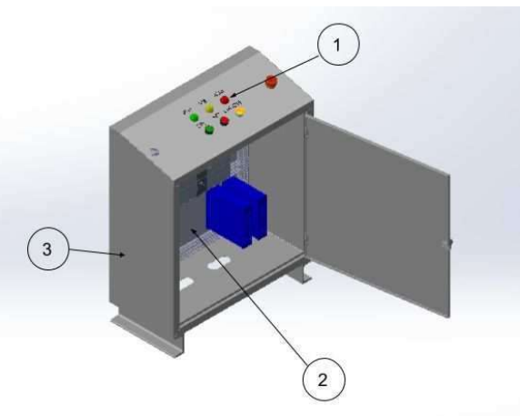
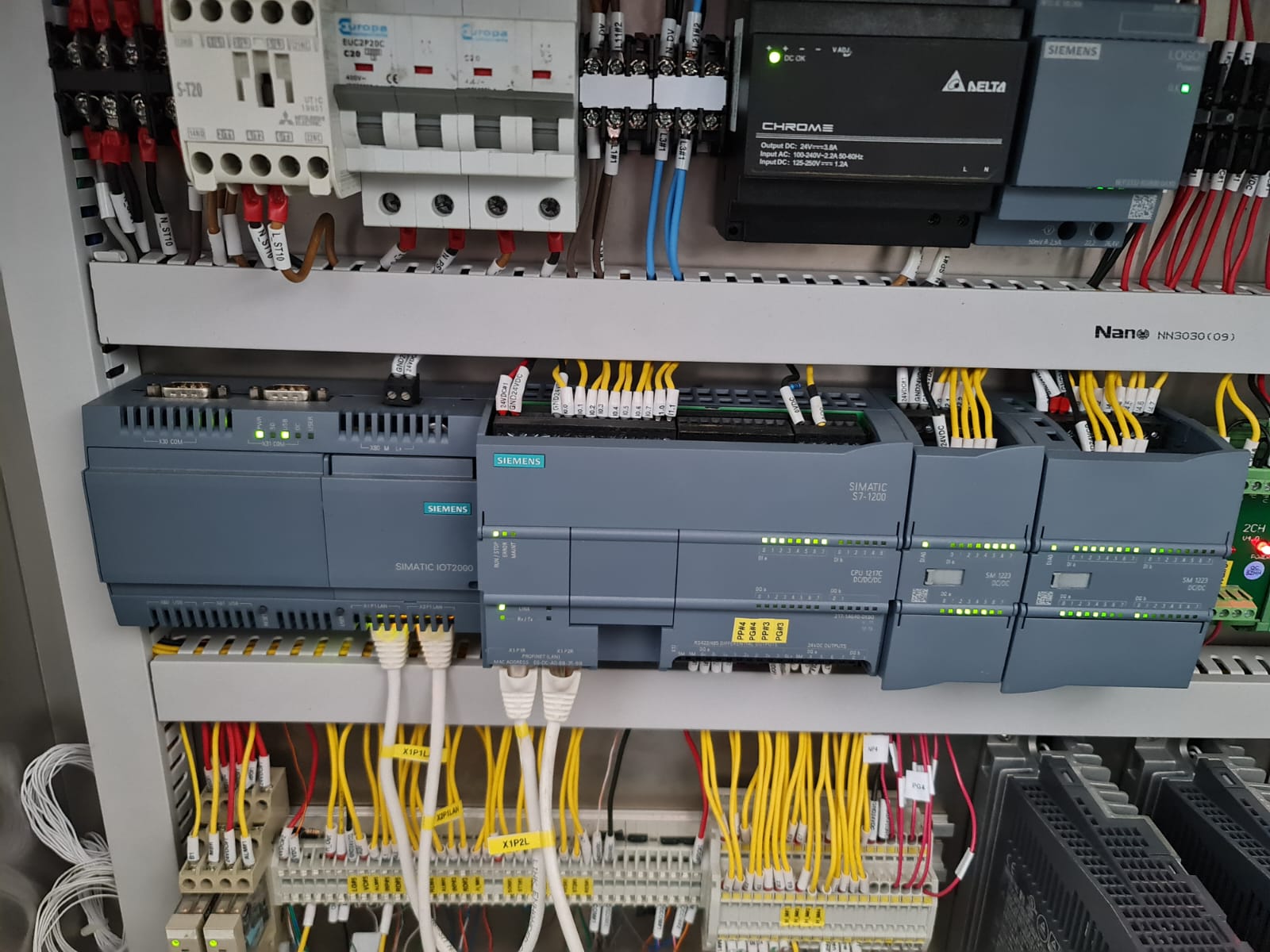
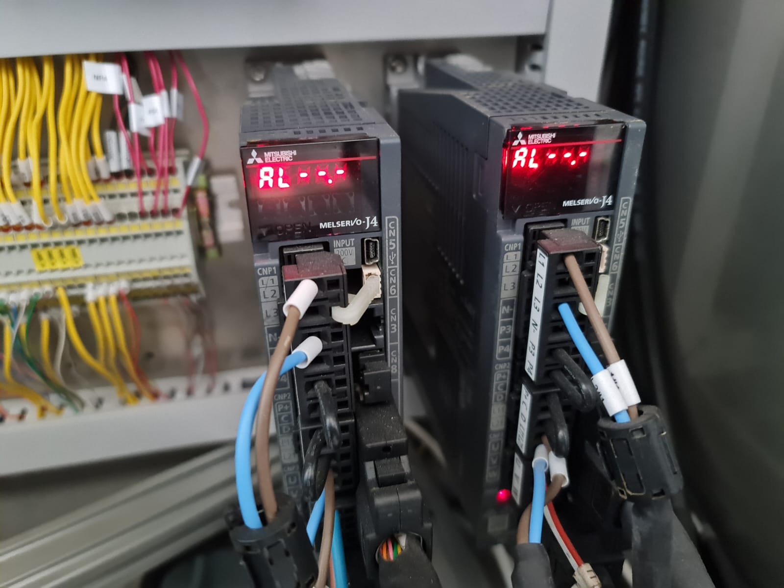
The maximum speed of 150 rpm was selected to balance operational throughput with mechanical safety limits, while the 0.1-degree resolution ensured high positional accuracy suitable for medical-grade manufacturing. The vertical moving mechanism provided precise height adjustments with a resolution of 1 mm over a 500 mm stroke. The maximum load capacity of 80 N ensured that the vertical stage could handle the necessary tooling and workpiece without motor overload. The entire system operated on a 220 VAC, 50 Hz supply, which was converted to appropriate control and drive voltages within the control cabinet. The control box housed the PLC, motor drivers, power supplies, safety relays, and communication modules. The PLC acted as the brain of the system, receiving input signals from position sensors, limit switches, and encoders, and sending output commands to servo or stepper motors via their respective drivers [3].
Hardware Design
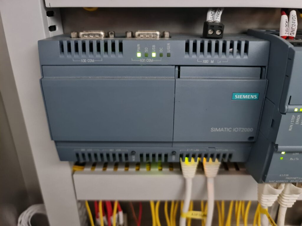
I selected hardware components based on durability, precision, and compatibility with the PLC system. The motors used for both the circular track and the vertical movement were high-torque servo motors with integrated encoders to provide real-time position feedback to the PLC. The encoders had sufficient resolution to achieve the desired 0.1-degree rotational precision and 1 mm linear resolution. For motion control, I used servo drives capable of closed-loop control, ensuring smooth acceleration and accurate positioning without overshoot. The PLC system was chosen from a reliable industrial-grade manufacturer, offering sufficient I/O capacity, high-speed counters, and Ethernet communication capability. I integrated proximity sensors and optical encoders to track mechanical positions, along with limit switches to define safe travel boundaries for both axes. The control cabinet design included a cooling fan system to maintain optimal temperatures for electronics, as well as cable management systems to ensure safety and serviceability [4].

You can download the Project files here: Download files now. (You must be logged in).
PLC Control System Development
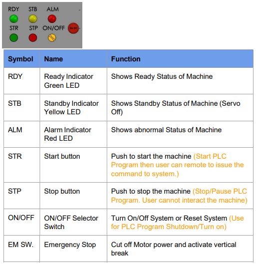
In developing the PLC control logic, I first mapped out the machine’s operational sequence in a flowchart. The process began with a homing sequence, during which both axes would return to their reference positions using limit switches and encoder feedback. Once homed, the operator could issue movement commands via the PC interface or local control panel. The PLC program included separate motion control routines for the circular track and vertical movement, each with adjustable acceleration, velocity, and position parameters. I implemented PID (Proportional-Integral-Derivative) control loops for precise motion handling, tuned to achieve smooth starts and stops without oscillation or overshoot. Safety interlocks were programmed to immediately stop motion in case of sensor faults, overtravel detection, or emergency stop activation. The PLC also generated event logs for every parameter change, movement command, and fault event, ensuring full traceability [5].
You can download the Project files here: Download files now. (You must be logged in).
Software and Programming
I programmed the PLC using ladder logic and function block diagrams, with separate routines for motion control, safety monitoring, and communication handling. The PC interface was developed to communicate with the PLC via Ethernet, using a command-line interface (CLI) that allowed technicians to issue commands such as “Set Position,” “Read Position,” “Set Velocity,” and “Start Motion.” The software handled both write and read operations, meaning that the operator could send commands to set parameters and also request real-time position and status updates from the PLC. Event logging was implemented on the PC side as well, where each received acknowledgment or error message from the PLC was recorded with a timestamp [6].
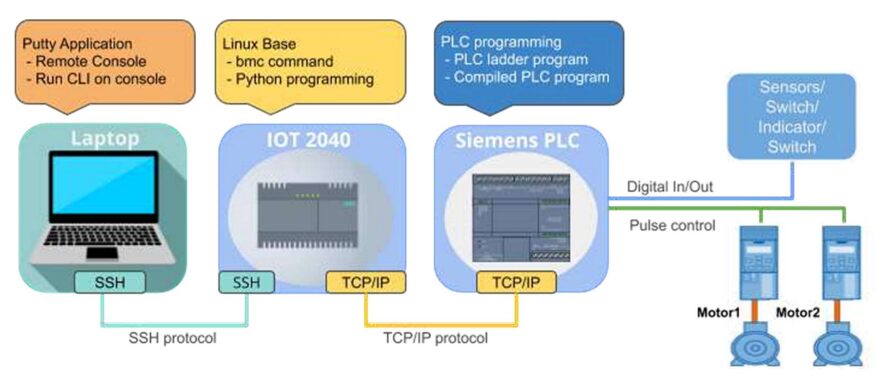
PC Interface via Ethernet
The Ethernet interface provided a reliable high-speed link between the PLC and the operator’s PC. I implemented a Modbus TCP protocol for communication, ensuring compatibility with multiple SCADA systems and diagnostic tools. Through the CLI, operators could home the machine, set motion parameters, start and stop movements, and query current positions. I also incorporated password-protected access levels, so that only authorized personnel could change critical motion parameters. Non-technical operators could use a simplified GUI overlay on top of the CLI, which I designed to execute predefined motion routines without requiring command syntax knowledge [7].
Control Parameters (Acceleration, Position, Velocity)
One of the key features I developed was the ability for operators to adjust acceleration, position, and velocity parameters on the fly. For example, if the process required slower rotation to prevent product damage, the operator could reduce the velocity from the PC interface and have the new parameter take effect immediately. Acceleration values were set to balance speed with mechanical stress minimization, ensuring that the motors and gear assemblies were not subjected to sudden forces. The position parameter allowed absolute and relative movements, with encoder feedback ensuring that commanded positions matched actual mechanical positions within allowable tolerances. All changes to these parameters were logged for traceability [8].
You can download the Project files here: Download files now. (You must be logged in).
Safety and Reliability Considerations
Given that the BMC machine operates in a medical manufacturing environment, safety and reliability were paramount. I implemented redundant limit switches on both axes to prevent accidental overtravel. The PLC was programmed with immediate fault detection and stop routines for motor overcurrent, encoder signal loss, or emergency stop activation. The control cabinet was designed to IP54 standards to protect against dust and accidental water splashes. I also performed failure mode and effects analysis (FMEA) to identify possible points of failure and implemented mitigations, such as surge protection on the power supply and watchdog timers in the PLC program [9].
Testing and Performance Results
During commissioning, I conducted multiple test cycles to verify accuracy, repeatability, and response times. The circular track consistently achieved 0.1-degree resolution at speeds up to 150 rpm without overshoot. The vertical movement achieved 1 mm accuracy over the full 500 mm stroke, even under maximum load conditions. The homing sequence was completed within 4 seconds, and communication latency between the PC interface and PLC remained under 50 ms, ensuring near-instantaneous response to operator commands. These results confirmed that the system met and exceeded the initial design specifications [10].
Challenges Faced and Solutions Implemented
One major challenge was integrating the PLC motion control with the existing mechanical structure of the BMC machine without modifying its core design. I overcame this by designing custom mounting brackets and couplings that allowed the servo motors to drive the existing shafts and lead screws. Another challenge was achieving smooth motion control at both low and high speeds without resonance issues. I solved this by fine-tuning the PID parameters and adding mechanical dampers where necessary. Communication stability was also a concern, as industrial environments can introduce electrical noise on Ethernet cables. I mitigated this by using shielded Ethernet cables and configuring the PLC for robust error-checking on communication packets [11].
Conclusion
In conclusion, the development of the industrial automation system for the BMC machine successfully transformed it from a semi-manual setup into a highly precise, reliable, and operator-friendly automated platform. By integrating the upper circular track and outer vertical moving mechanisms into a PLC-based control system, I achieved enhanced positional accuracy, consistent motion profiles, and greater operational efficiency. The use of servo motors with encoder feedback ensured that both rotational and linear movements were executed with exceptional precision, meeting the stringent requirements of SENSOMEDICAL’s applications. The Ethernet-based PC interface provided flexibility in control, allowing operators to adjust acceleration, velocity, and position in real time while maintaining a complete event log for traceability and compliance. Safety was given top priority, with redundant limit switches, emergency stops, and robust electrical protection implemented to prevent damage to the machine or harm to personnel. The project also addressed key challenges, including integrating new automation hardware with the existing mechanical structure and mitigating electrical noise in industrial communication lines. Through rigorous testing and commissioning, the system demonstrated smooth operation across its full speed range, achieving the specified maximum speeds and resolutions without overshoot or instability. The improvements not only increased throughput but also reduced downtime and maintenance requirements, thereby enhancing the machine’s lifecycle value. Moreover, the scalable architecture of the PLC program and hardware setup allows for future expansions, such as integration with advanced monitoring systems, automated quality control, or robotics for material handling. This project exemplifies how carefully engineered industrial automation can bridge the gap between precision manufacturing demands and efficient operational workflows. Overall, the automation of the BMC machine stands as a robust, adaptable, and future-ready solution that delivers measurable benefits in productivity, quality, and safety, positioning it as a benchmark for similar industrial applications in the medical manufacturing sector.
References
[1] Bolton, W. Programmable Logic Controllers, 7th ed., Newnes, 2015.
[2] Petruzella, F. D. Programmable Logic Controllers, McGraw-Hill Education, 2016.
[3] Groover, M. P. Automation, Production Systems, and Computer-Integrated Manufacturing, 4th ed., Pearson, 2015.
[4] Hughes, T. Electrical and Electronic Technology, Pearson, 2012.
[5] Lipták, B. G. Instrument Engineers’ Handbook: Process Control and Optimization, CRC Press, 2018.
[6] Parr, E. A. Programmable Controllers: An Engineer’s Guide, Newnes, 2011.
[7] Webb, J., and Reis, R. Programmable Logic Controllers: Principles and Applications, Pearson, 2012.
[8] National Instruments. “Motion Control Fundamentals.” NI White Paper, 2020.
[9] IEC 60204-1. Safety of Machinery – Electrical Equipment of Machines – Part 1: General Requirements. IEC, 2016.
[10] Rockwell Automation. “PLC Motion Control Best Practices.” Rockwell Technical Report, 2019.
[11] Siemens AG. “Industrial Communication Networks – Ethernet.” Siemens Technical Guide, 2020.
[12] Beckhoff Automation. “Precision Motion Control with PLC Integration.” Beckhoff White Paper, 2018.
[13] ISO 13849-1. Safety of Machinery – Safety-related Parts of Control Systems – Part 1: General Principles for Design. ISO, 2015.
You can download the Project files here: Download files now. (You must be logged in).


Responses