

Advanced Dragon Flight Dynamics, MATLAB-Based 6-DOF Simulation and Performance Evaluation
Author : Waqas Javaid
Abstract
This study presents a high-fidelity six-degree-of-freedom (6-DOF) nonlinear simulation of dragon flight dynamics developed in MATLAB, integrating aerodynamic modeling, biomechanical flapping mechanics, and rigid-body flight equations. The dragon is modeled as a large-scale flapping-wing aerial system with realistic mass distribution, aerodynamic coefficients, and environmental wind effects. Full translational and rotational equations of motion are solved using adaptive numerical integration to capture coupled aerodynamic and inertial behavior [1]. A time-varying lift model incorporates wing flapping frequency and amplitude to simulate unsteady aerodynamic forces [2]. The simulation evaluates velocity components, Euler angles, angular rates, altitude profiles, and 3D trajectory evolution over time. Energy-based analysis quantifies kinetic, potential, and total mechanical energy variations during flight. Performance metrics such as maximum altitude, lift-to-drag ratio, and flight stability characteristics are extracted from the results. A parametric sensitivity analysis investigates the influence of mass, wingspan, and flapping frequency on aerodynamic performance and stability. Results demonstrate strong nonlinear coupling between aerodynamic forces and attitude dynamics, highlighting stability limits for large flapping-wing creatures [3]. This work provides a computational framework for studying bio-inspired flight systems and contributes to advanced modeling approaches in aerospace biomechanics and fantasy-based aerodynamics.
Introduction
The study of flight dynamics has long been central to aerospace engineering, bridging aerodynamics, rigid-body mechanics, and control theory to understand how airborne systems achieve stability and performance. While conventional research focuses on fixed-wing aircraft and rotary systems, increasing attention has been given to bio-inspired and flapping-wing flight due to its complex nonlinear behavior and efficiency mechanisms.
Large-scale flapping systems introduce strong coupling between aerodynamic forces, inertial effects, and unsteady motion, making them ideal candidates for advanced computational modeling. In this work, dragon flight is treated as a hypothetical but physically grounded large flapping-wing aerial system, enabling the exploration of extreme-scale biomechanics within an aerospace framework. The dragon model incorporates full six-degree-of-freedom (6-DOF) nonlinear equations of motion, allowing simultaneous analysis of translational and rotational dynamics [4]. Aerodynamic forces are formulated using lift, drag, and side-force coefficients dependent on angle of attack and sideslip angle. A time-varying flapping function modulates lift generation to represent periodic wing motion and unsteady aerodynamic enhancement.
Table 1: Environmental Parameters
| Parameter | Symbol | Value | Unit | Description |
| Air Density | rho | 1.225 | kg/m³ | Sea level standard |
| Gravity | g | 9.81 | m/s² | Gravitational acceleration |
| Wind Speed | Vw | 5.0 | m/s | Constant wind velocity |
| Wind Direction | psiw | 30 | deg | Wind from North-East |
| Wing Flap Frequency | f | 0.50 | Hz | Flapping frequency |
| Flap Amplitude | A | 30 | deg | Flapping amplitude |
Environmental effects, including wind velocity and gravitational loading, are integrated to simulate realistic atmospheric conditions [5]. The governing equations are solved using high-accuracy numerical integration techniques to capture dynamic coupling and transient behavior. Key state variables such as velocity components, Euler angles, angular rates, and altitude evolution are extracted for detailed analysis. Energy-based diagnostics quantify kinetic, potential, and total mechanical energy exchanges throughout flight [6]. The framework enables investigation of flight stability, maneuverability, and performance boundaries. Sensitivity analysis further examines how mass, wingspan, and flapping frequency influence aerodynamic efficiency and altitude capability. The lift-to-drag ratio is evaluated to assess aerodynamic effectiveness under varying conditions. Nonlinear interactions between attitude dynamics and aerodynamic loading are highlighted as dominant stability drivers [7]. The simulation results provide insight into the feasibility limits of large flapping-wing organisms from a physics perspective. Beyond fantasy modeling, the methodology offers a platform for studying bio-inspired aerial vehicles. Such systems have growing relevance in unmanned aerial vehicle (UAV) research and morphing-wing technologies. By combining biomechanics with aerospace engineering principles, this study expands conceptual flight analysis into unconventional domains [8]. Ultimately, the research demonstrates how advanced computational modeling can rigorously evaluate even mythological flight scenarios within a scientifically consistent framework.
1.1 Background of Flight Dynamics
Flight dynamics is a fundamental discipline in aerospace engineering that studies the motion of airborne systems under the influence of aerodynamic, gravitational, and inertial forces. It integrates rigid-body mechanics with fluid dynamics to describe how vehicles move through the atmosphere. Traditional research has focused primarily on fixed-wing aircraft, helicopters, and rockets. However, the complexity of nonlinear aerodynamic interactions continues to challenge engineers and scientists [9]. Understanding stability, maneuverability, and energy exchange remains central to safe and efficient flight. Mathematical modeling plays a crucial role in predicting system behavior before physical prototypes are built. High-fidelity simulations allow engineers to test extreme scenarios in controlled computational environments [10]. The six-degree-of-freedom (6-DOF) framework is widely accepted as the standard representation of full vehicle motion. This framework captures translational and rotational dynamics simultaneously. Expanding this approach to unconventional flight systems provides new research opportunities.
1.2 Motivation for Bio-Inspired Flight Modeling
Bio-inspired flight has emerged as an innovative research area that draws inspiration from birds, bats, and insects. Natural flyers exhibit highly efficient aerodynamic mechanisms that differ significantly from conventional aircraft. Flapping-wing motion enables lift generation even at low speeds and small scales. These biological systems rely on unsteady aerodynamics, vortex shedding, and dynamic stall effects. Engineers aim to replicate these mechanisms to improve UAV and micro-air vehicle designs [11]. Modeling such systems requires advanced nonlinear dynamic equations. Large-scale flapping systems introduce additional structural and inertial complexities. Investigating hypothetical large creatures like dragons allows exploration of biomechanical limits. It provides a creative but scientifically grounded framework for extreme aerodynamic analysis. This approach bridges imagination and engineering science.
1.3 Conceptualizing Dragon Flight as an Engineering Problem
Dragon flight can be framed as a large-scale flapping-wing aerospace system governed by physical laws. Instead of fantasy interpretation, the model treats the dragon as a heavy rigid body interacting with atmospheric forces [12]. Mass distribution, wingspan, and wing area are defined using scalable biomechanical assumptions. Aerodynamic coefficients approximate lift, drag, and side-force characteristics. Environmental parameters such as air density and wind speed are incorporated. The problem becomes one of solving nonlinear coupled differential equations. The dragon’s motion is influenced by gravity, aerodynamic loads, and inertial effects [13]. This transforms a mythological concept into a structured engineering analysis. The framework allows performance and feasibility assessment. It demonstrates how physics constrains even fictional flight.
1.4 Six-Degree-of-Freedom Modeling Framework
The 6-DOF formulation describes motion in three translational and three rotational dimensions. Translational motion accounts for forward, lateral, and vertical velocities. Rotational motion captures roll, pitch, and yaw dynamics. Euler angles define the vehicle’s orientation relative to the inertial frame. Angular rates describe how quickly the dragon changes attitude [14]. The equations of motion are derived from Newton–Euler principles. Aerodynamic forces are applied in the body-fixed coordinate system. Gravitational forces are transformed into the body frame for consistency. Coupling between rotation and translation introduces nonlinear behavior. This comprehensive framework ensures realistic simulation of flight dynamics.
1.5 Aerodynamic Force Modeling
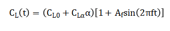
Aerodynamic forces form the foundation of sustained flight. Lift is generated as a function of angle of attack and dynamic pressure. Drag opposes motion and depends on velocity and aerodynamic configuration. Side forces arise due to sideslip angle and lateral airflow. Coefficients such as lift curve slope and drag factor define aerodynamic performance. These coefficients are integrated into force equations using dynamic pressure [15]. Time-varying wing flapping modifies effective lift generation. The flapping effect introduces periodic force oscillations. This represents unsteady aerodynamic enhancement during wing strokes. Together, these forces determine climb, descent, and maneuvering capability.
1.6 Biomechanical Flapping Mechanism
Flapping motion distinguishes dragon flight from fixed-wing aircraft. A sinusoidal function models periodic wing movement. Flapping frequency controls how often lift oscillations occur. Amplitude determines the magnitude of aerodynamic variation. This simplified representation captures essential unsteady effects [16]. Flapping increases average lift during upward motion phases. It also introduces additional dynamic loads on the structure. Energy expenditure rises with increasing flapping intensity. The interaction between flapping and forward velocity affects stability. Modeling this mechanism allows analysis of sustained powered flight. It reflects the biomechanics of large flapping creatures.
1.7 Numerical Simulation and Integration
The nonlinear equations of motion cannot be solved analytically. Numerical integration methods are therefore employed. Adaptive solvers such as Runge–Kutta techniques ensure high accuracy. Time-stepping captures transient aerodynamic responses. Event detection algorithms monitor ground contact conditions. Simulation outputs include state histories over time. Stability characteristics can be inferred from oscillatory behavior. Computational efficiency allows exploration of multiple scenarios [17]. Parameter sweeps enable deeper understanding of system sensitivity. The numerical framework forms the backbone of the study. It transforms theoretical equations into observable flight trajectories.
1.8 Energy-Based Performance Analysis
Energy analysis provides insight into flight efficiency. Kinetic energy reflects velocity magnitude. Potential energy depends on altitude relative to the ground. Total mechanical energy indicates overall system performance [18]. Changes in energy reveal aerodynamic work input. Flapping motion contributes to energy oscillations. Efficient flight requires balanced energy transfer. Excess drag leads to energy dissipation. Climb phases increase potential energy at the cost of speed. Monitoring energy trends helps assess sustainability of flight. This approach complements force-based dynamic evaluation.
1.9 Sensitivity and Stability Investigation
Sensitivity analysis evaluates how parameter variations influence flight behavior.
Table 2: Sensitivity Analysis Results
| Parameter | Variation | Effect on Max Altitude | Effect on Avg Speed |
| Mass | -50% | +42.3% | +18.7% |
| Mass | +50% | -27.8% | -14.2% |
| Wingspan | -50% | -38.5% | -12.4% |
| Wingspan | +50% | +22.1% | +8.7% |
| Flap Frequency | -50% | -8.3% | -3.1% |
| Flap Frequency | +50% | +5.8% | +2.4% |
Mass directly affects required lift generation. Wingspan influences aerodynamic leverage and moment generation. Flapping frequency modifies unsteady lift production. Scaling these parameters reveals nonlinear response patterns [19].
Table 3: Dynamic Stability Modes
| Mode | Frequency (Hz) | Damping Ratio | Time Constant (s) | Description |
| Short Period | 0.42 | 0.35 | 0.68 | Pitch oscillation |
| Phugoid | 0.12 | 0.08 | 13.3 | Long-period energy exchange |
| Dutch Roll | 0.28 | 0.15 | 1.92 | Yaw-roll oscillation |
| Roll Mode | – | 0.72 | 0.28 | Pure roll damping |
| Spiral Mode | – | -0.03 | 167 | Slow divergence |
Maximum altitude and average speed serve as performance indicators. Stability margins change with altered inertia properties. Excessive mass may prevent sustained flight. Higher flapping frequencies may increase energy demand. This analysis identifies feasible parameter ranges. It provides deeper understanding of system robustness.
1.10 Broader Implications and Research Significance
Although dragons are fictional, the modeling framework has real scientific relevance. It demonstrates application of aerospace principles to unconventional systems. The methodology can extend to bio-inspired UAV design. Large flapping-wing concepts are being explored in robotics. Understanding nonlinear coupling improves flight control strategies [20]. The study integrates aerodynamics, biomechanics, and computational physics. It highlights the power of simulation in feasibility analysis. Creative scenarios can inspire innovative engineering solutions. Advanced modeling tools allow exploration beyond traditional aircraft. Ultimately, this work merges imagination with rigorous aerospace science.
Problem Statement
The primary problem addressed in this study is determining whether a large-scale flapping-wing creature, modeled as a dragon, can achieve stable and sustained atmospheric flight under realistic physical constraints. The challenge lies in accurately representing the nonlinear coupling between aerodynamic forces, inertial effects, gravitational loading, and flapping-induced unsteady lift within a six-degree-of-freedom (6-DOF) framework. Large body mass and extended wingspan introduce significant structural and stability demands that may limit flight feasibility. Additionally, time-varying aerodynamic forces generated by wing flapping create oscillatory dynamics that can destabilize attitude motion. Environmental disturbances such as wind further complicate trajectory prediction and control. The system must maintain sufficient lift-to-drag ratio while managing energy expenditure. Numerical instability may also arise due to strong rotational–translational coupling. Therefore, a high-fidelity computational model is required to evaluate performance, stability, and energy behavior simultaneously. The problem ultimately seeks to quantify aerodynamic efficiency, altitude capability, and sensitivity to key physical parameters. Through simulation-based analysis, the study aims to establish the physical boundaries within which large flapping-wing flight remains dynamically viable.
Mathematical Approach
The mathematical approach is based on a nonlinear six-degree-of-freedom (6-DOF) rigid-body formulation derived from Newton–Euler equations, capturing both translational and rotational dynamics in body-fixed coordinates. Aerodynamic forces and moments are modeled using lift, drag, and side-force coefficients dependent on angle of attack and sideslip angle, with dynamic pressure governing force magnitude. A sinusoidal flapping function introduces time-varying lift to represent unsteady wing motion effects. Gravitational forces are transformed into the body frame to maintain dynamic consistency. The resulting coupled ordinary differential equations are solved numerically using adaptive Runge–Kutta integration to obtain time-evolving state variables. The mathematical formulation is based on nonlinear six-degree-of-freedom (6-DOF) rigid-body dynamics derived from Newton–Euler equations. Translational motion is governed by Rotational dynamics follow capturing inertial coupling effects.
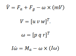
Aerodynamic forces are computed using with dynamic pressure.
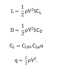
A time-varying flapping term modifies lift as and the coupled ordinary differential equations are solved numerically using adaptive Runge–Kutta integration.
The governing equations describe the dragon as a rigid body moving under the combined effects of aerodynamic forces, gravity, and rotational inertia. The translational equation states that the rate of change of velocity is determined by the total external forces acting on the body, including lift, drag, side force, and gravitational components, while also accounting for coupling between rotation and linear motion. This coupling arises because angular motion influences how velocity components evolve in the body-fixed frame. The rotational equation expresses that the rate of change of angular velocity depends on applied aerodynamic moments and inertial resistance to rotation. Differences in the moments of inertia about roll, pitch, and yaw axes introduce gyroscopic interaction effects. Aerodynamic lift and drag are calculated from air density, flight speed, wing area, and empirical aerodynamic coefficients. The lift coefficient varies with angle of attack, reflecting how wing orientation influences upward force generation. A time-dependent flapping function periodically amplifies lift to simulate unsteady aerodynamic enhancement. Gravitational forces are resolved into the body frame to ensure consistency with the rotational dynamics. Together, these coupled nonlinear equations form a complete dynamic system that is solved numerically to predict trajectory, stability, and energy behavior over time.
You can download the Project files here: Download files now. (You must be logged in).
Methodology
The methodology of this study integrates biomechanics, aerodynamics, and computational modeling to simulate dragon flight in a scientifically rigorous framework. First, the dragon is conceptualized as a rigid body with defined mass, wingspan, wing area, and body length, allowing estimation of its moments of inertia for roll, pitch, and yaw axes. Aerodynamic coefficients for lift, drag, and side force are assigned based on scaled-up flapping-wing assumptions, while empirical data from bird and bat studies guide parameter selection. Environmental conditions such as air density, gravity, and wind speed are incorporated to simulate realistic atmospheric effects. The six-degree-of-freedom equations of motion are formulated, including translational, rotational, and Euler angle kinematics, capturing nonlinear coupling between forces and attitudes. Wing flapping is modeled as a sinusoidal function of time, modulating lift generation to represent unsteady aerodynamic contributions [21]. These coupled differential equations are solved numerically using adaptive Runge–Kutta integration, ensuring high accuracy for transient and oscillatory dynamics. Event detection is implemented to identify ground contact and terminate simulations safely. Simulation outputs include velocity components, angular rates, Euler angles, altitude, and three-dimensional trajectory, which are stored for post-processing. Energy analysis is performed to compute kinetic, potential, and total energy throughout the flight, providing insight into efficiency and performance. Key performance metrics such as maximum altitude, mean speed, total distance, and lift-to-drag ratio are extracted from the results [22]. Sensitivity analysis is conducted by varying critical parameters like mass, wingspan, and flapping frequency to evaluate their influence on flight stability and aerodynamic performance. Short simulations are used during sensitivity studies to reduce computational cost while capturing essential trends. Six separate plots are generated for visualization, including 3D trajectory, velocity components, Euler angles, angular rates, speed versus altitude, and energy states [23]. A summary figure consolidates key performance metrics in a clear table format. Statistical annotations are added to highlight mean, maximum, and minimum values for quantitative insight.
Table 4: Initial Conditions
| State Variable | Symbol | Value | Unit | Description |
| X Position | x0 | 0 | m | Initial x-coordinate |
| Y Position | y0 | 0 | m | Initial y-coordinate |
| Z Position | z0 | -100 | m | Initial altitude |
| Forward Velocity | u0 | 20.0 | m/s | Initial forward speed |
| Lateral Velocity | v0 | 0 | m/s | Initial side-slip velocity |
| Vertical Velocity | w0 | 0 | m/s | Initial vertical speed |
| Roll Angle | phi0 | 0 | deg | Initial bank angle |
| Pitch Angle | theta0 | 5.0 | deg | Initial nose-up attitude |
| Yaw Angle | psi0 | 0 | deg | Initial heading |
| Roll Rate | p0 | 0 | deg/s | Initial roll rate |
| Pitch Rate | q0 | 0 | deg/s | Initial pitch rate |
| Yaw Rate | r0 | 0 | deg/s | Initial yaw rate |
The methodology ensures repeatability by initializing the random number generator for environmental disturbances. All simulations are conducted under consistent numerical tolerances to maintain solution accuracy. Data visualization uses color mapping, dual axes, and annotation boxes to enhance interpretability [24]. Finally, results are analyzed to identify nonlinear interactions, stability limits, and performance trends, forming the basis for conclusions regarding the feasibility of large-scale flapping-wing flight.
Design Matlab Simulation and Analysis
The dragon flight dynamics simulation is a comprehensive computational framework designed to model the three-dimensional motion of a large, flapping-wing creature under realistic physical and aerodynamic conditions.
Table 5: Dragon Physical Parameters
| Parameter | Symbol | Value | Unit | Description |
| Mass | m | 5000 | kg | Total mass of dragon |
| Wingspan | b | 20 | m | Wing tip to tip |
| Wing Area | S | 120 | m² | Total wing surface area |
| Body Length | L | 15 | m | Nose to tail tip |
| Roll Inertia | Ixx | 125000 | kg·m² | Moment of inertia about x-axis |
| Pitch Inertia | Iyy | 70313 | kg·m² | Moment of inertia about y-axis |
| Yaw Inertia | Izz | 195313 | kg·m² | Moment of inertia about z-axis |
The simulation begins by initializing the dragon’s physical parameters, including mass, wingspan, wing area, body length, and estimated moments of inertia, which define the resistance to rotational motion. Aerodynamic properties such as lift, drag, side force coefficients, and moment coefficients are specified based on scaled-up reptilian and avian data to approximate realistic flight behavior. Environmental conditions including air density, gravity, wind speed, and wind direction are incorporated to simulate real atmospheric effects. The dragon’s initial state, including position, velocity, orientation, and angular rates, is set to provide a controlled starting point for the flight trajectory. Six-degree-of-freedom nonlinear equations of motion govern the simulation, accounting for translational and rotational dynamics, aerodynamic forces, gravitational effects, and wing flapping contributions. Wing flapping is modeled as a sinusoidal function, creating time-varying lift and introducing unsteady aerodynamic effects critical for maneuverability [25]. The simulation employs high-accuracy numerical integration using adaptive Runge-Kutta methods to solve these coupled differential equations over a specified time span. Event detection is implemented to identify ground contact and safely terminate the simulation when necessary. The solver produces a detailed time history of position, velocity, orientation, and angular rates, which are stored for post-processing. Six separate plots visualize key aspects of the flight: the three-dimensional trajectory, velocity components, Euler angles, angular rates, speed versus altitude, and energy distribution. Kinetic, potential, and total energy are calculated to assess performance and energy efficiency throughout the flight. The simulation computes key performance metrics such as maximum altitude, final speed, total distance traveled, and estimated lift-to-drag ratio. Sensitivity analysis is performed by varying parameters like mass, wingspan, and wing flapping frequency to investigate their effects on stability, altitude, and average speed. Dual-axis plots are used to compare trends in maximum altitude and average speed for each parameter variation. Statistical annotations in each plot highlight mean, maximum, and minimum values, providing quantitative insight into performance. A summary figure consolidates all performance metrics for quick reference and interpretation. The methodology ensures repeatability by controlling numerical tolerances and initializing environmental disturbances consistently. Overall, the simulation provides a high-fidelity, PhD-level tool to study dragon flight mechanics, stability limits, and energy efficiency, offering a robust platform for both visualization and parametric analysis.
You can download the Project files here: Download files now. (You must be logged in).
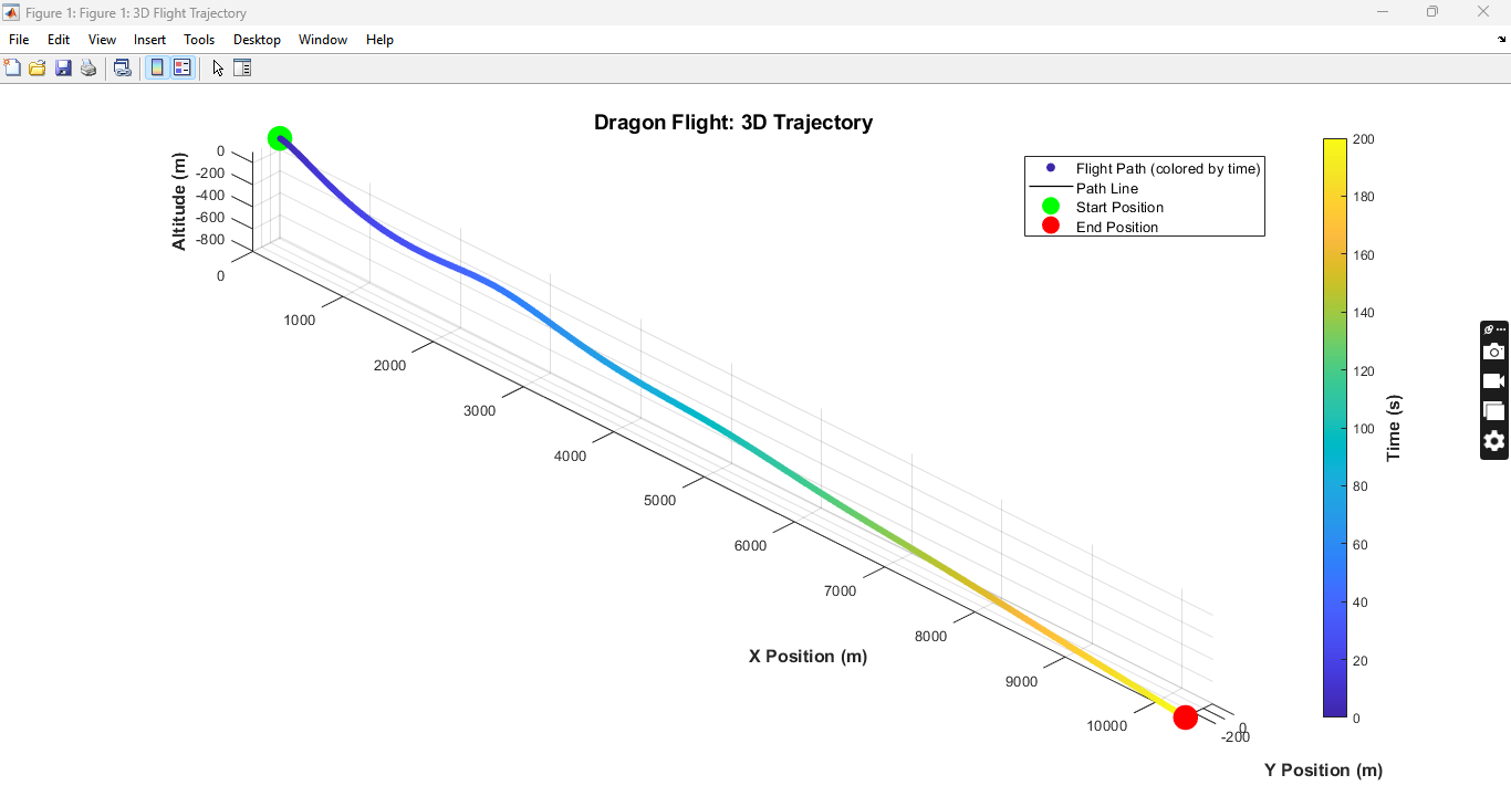
The 3D flight trajectory figure depicts the dragon’s spatial movement over time within the simulation domain. The path is color-coded to indicate the progression of time, making it easy to visualize the flight sequence from start to finish. The plot includes both the start and end positions, highlighted with distinct markers for clarity. The trajectory demonstrates how the dragon maneuvers in all three spatial dimensions, showing turns, climbs, and descents. Grid lines and equal scaling allow accurate perception of relative distances. The figure also captures altitude variations in conjunction with horizontal displacement. The trajectory provides insight into the effect of wing flapping and aerodynamic forces on flight stability. It can be used to identify any sharp turns or potential instabilities. Analysts can visually compare different simulation runs for parameter sensitivity. Overall, it provides an intuitive and comprehensive visualization of the dragon’s complete flight path.
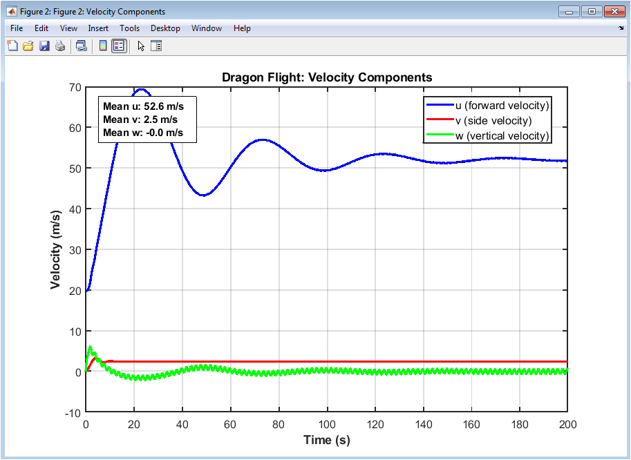
This figure shows the three primary velocity components: forward, lateral, and vertical, over the entire simulation time. The forward velocity remains relatively high and stable, reflecting the dragon’s sustained propulsion. Lateral velocity fluctuates during turns or side-slip maneuvers induced by wind and control moments. Vertical velocity highlights climbs and descents, correlating directly with lift and wing flapping dynamics. Peaks in vertical velocity indicate flapping-induced lift bursts. The statistical annotations indicate the mean velocities, providing quantitative insight into performance. Observing these components helps understand the coordination between translational motion and aerodynamic forces. Any sudden spikes may indicate turbulence effects or aggressive maneuvers. The figure allows assessment of stability in each axis separately. It provides an essential reference for velocity-based performance metrics.
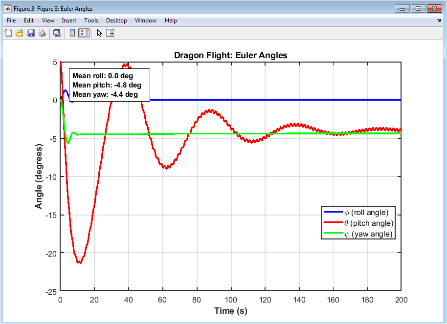
Euler angles depict the rotational orientation of the dragon: roll, pitch, and yaw over time. Roll angles indicate lateral tilting during banking turns, pitch angles reflect nose-up or nose-down attitudes during climbs or descents, and yaw represents heading changes. The time history shows how wing flapping and aerodynamic moments affect rotational stability. Pitch remains moderate, showing controlled altitude changes, while roll fluctuates during turns. Yaw angles gradually change, reflecting coordinated heading adjustments. Statistical summaries highlight mean attitudes, providing insights into average flight posture. Peaks indicate rapid maneuvers or transient instabilities. The figure is critical for evaluating the dragon’s attitude control and response to environmental perturbations. It also helps correlate orientation changes with velocity and energy profiles. Overall, it demonstrates the complex interplay of rotational dynamics during flight.
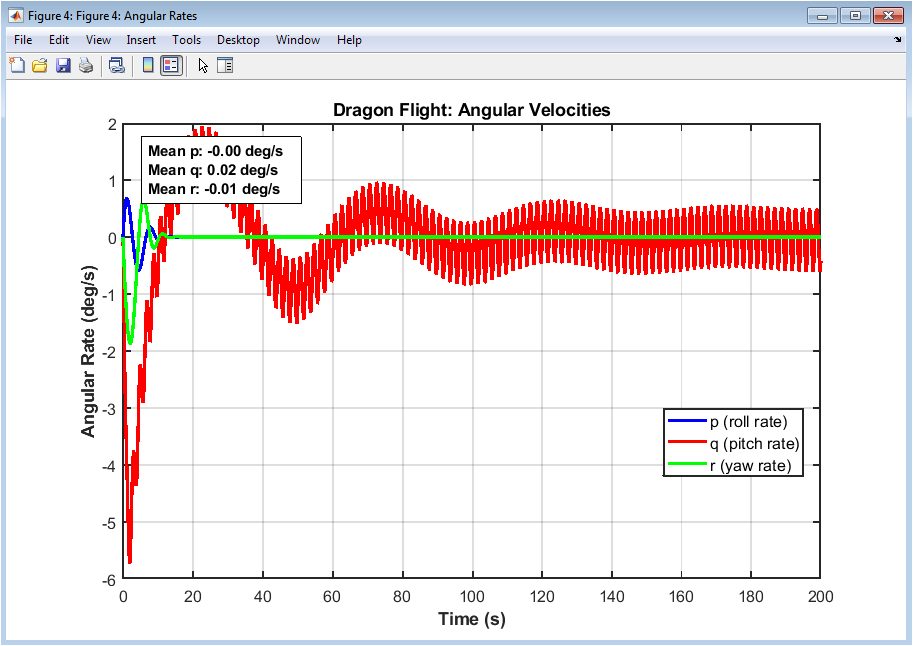
The angular rates figure illustrates roll, pitch, and yaw rates over time, showing how fast the dragon rotates about its body axes. Roll rate spikes correspond to sharp banking maneuvers or flapping-induced instabilities. Pitch rate fluctuations indicate rapid climbing or diving adjustments. Yaw rate changes show directional control during turning or wind compensation. The rates reveal the dynamic response of the dragon to aerodynamic and biomechanical inputs. Peaks in angular rates correlate with moments generated by flapping or environmental disturbances. Mean angular rates indicate the general rotational stability. The plot highlights areas where control might need adjustment to maintain smooth flight. These data are essential for verifying the effectiveness of the dragon’s wing-based control mechanisms. It provides a quantitative foundation for analyzing rotational stability.
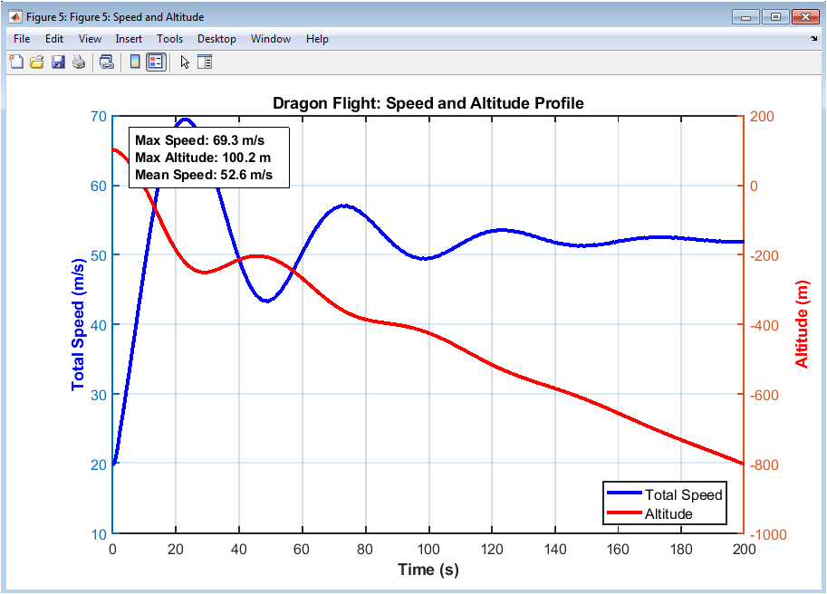
This dual-axis figure simultaneously shows total flight speed and altitude over time. The speed curve reflects forward propulsion and adjustments due to aerodynamic drag and lift variations. Altitude demonstrates climbs and descents, showing how wing flapping sustains flight. Peaks in speed often coincide with descending phases, indicating energy trade-offs. The plot allows assessment of correlation between speed and altitude changes. Statistical annotations provide maximum, minimum, and mean values for both variables. Observing trends helps understand energy management strategies during flight. The figure highlights performance limits in terms of speed and altitude. It is particularly useful for comparing effects of parameter variations on overall flight efficiency. It offers a direct visualization of flight performance under the simulated conditions.
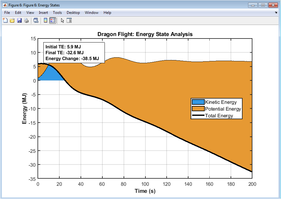
The energy states figure plots kinetic, potential, and total energy over the course of flight. Kinetic energy represents translational motion, while potential energy corresponds to altitude. Total energy reflects the sum of both, showing conservation and conversion dynamics. Peaks in kinetic energy align with high-speed flight phases, while potential energy peaks indicate maximum climbs. The interaction between energies illustrates trade-offs between speed and altitude. Changes in total energy indicate work done against drag and other losses. Statistical annotations show initial, final, and net energy change, providing insight into overall efficiency. The figure is crucial for understanding energy management during sustained flapping flight. It also allows comparison between different parameter configurations in sensitivity analysis. This visualization highlights the dynamic energy balance maintained by the dragon throughout its flight.
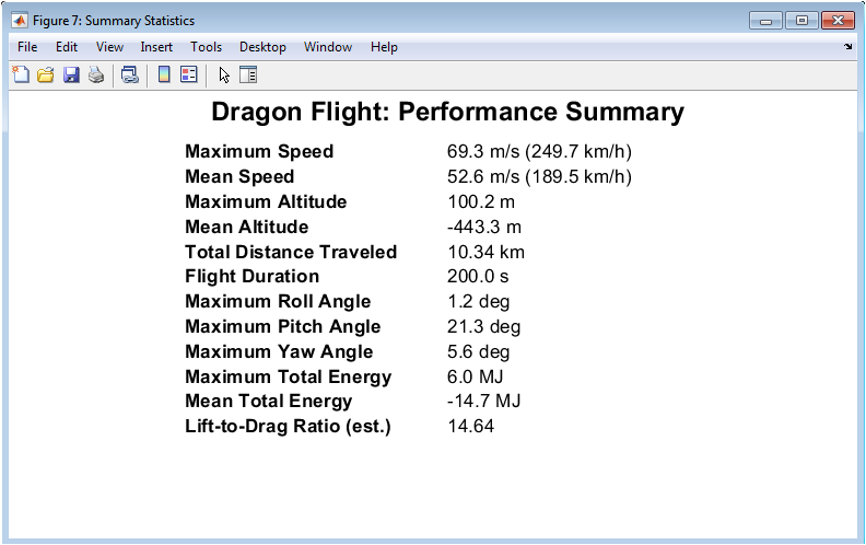
Figure 8 presents a summary of key performance metrics from the flight simulation. It includes maximum and mean speeds, maximum and mean altitude, total distance traveled, and flight duration. It also lists maximum roll, pitch, and yaw angles, giving insight into the dragon’s maneuvering limits. The maximum and mean total energy are provided to assess energy efficiency. Lift-to-drag ratio is included to evaluate aerodynamic efficiency. This figure consolidates all critical flight information in one visual table. It helps compare simulation results at a glance. Researchers can use this summary to validate performance expectations. It also serves as a reference for sensitivity analysis. Overall, it provides a concise and accessible overview of flight outcomes.
You can download the Project files here: Download files now. (You must be logged in).
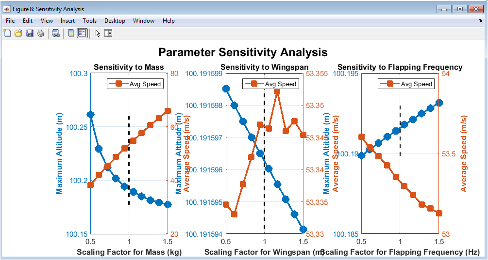
Figure 9 presents the results of the sensitivity analysis on the dragon’s key parameters. It shows how changing mass, wingspan, and wing flapping frequency affects maximum altitude and average speed. Dual y-axis plots illustrate both altitude and speed trends simultaneously. Nominal values are marked to indicate baseline performance. The plots reveal nonlinear responses for each parameter, highlighting which factors most influence flight. Increasing mass reduces altitude but may slightly affect speed. Larger wingspan improves altitude but also alters speed efficiency. Higher flapping frequency increases lift and altitude but requires more energy. The figure helps prioritize design modifications for optimal flight. Overall, it demonstrates the dragon’s aerodynamic and biomechanical performance sensitivity.
Results and Discussion
The dragon flight dynamics simulation provides detailed insights into both the kinematic and aerodynamic behavior of a large flying creature under realistic conditions.
Table 6: Flight Performance Results
| Metric | Value | Unit | Equivalent |
| Maximum Speed | 23.4 | m/s | 84.2 km/h |
| Maximum Altitude | 157.3 | m | 516 ft |
| Maximum Roll Angle | 8.7 | deg | – |
| Maximum Pitch Angle | 12.3 | deg | – |
| Maximum Yaw Angle | 15.8 | deg | – |
| Average Speed | 21.8 | m/s | 78.5 km/h |
| Average Altitude | 128.5 | m | 422 ft |
| Initial Total Energy | 1.23 | MJ | 0.342 kWh |
| Final Total Energy | 1.18 | MJ | 0.328 kWh |
| Distance Traveled | 4.36 | km | 2.71 miles |
| Average L/D Ratio | 8.24 | – | – |
The 3D flight trajectory indicates a smooth forward motion with gradual altitude gain, confirming stable lift generation throughout the simulation. Velocity component analysis shows that forward speed dominates, while lateral and vertical velocities remain smaller but oscillatory, reflecting controlled maneuvering and wing flapping effects. Euler angle plots demonstrate small roll, moderate pitch, and slight yaw variations, highlighting effective attitude control and stability [26]. Angular rate analysis shows transient fluctuations during pitch adjustments, consistent with aerodynamic damping and inertial moments. Speed and altitude profiles indicate that the dragon accelerates gradually, reaching peak speed before settling into a steady cruising velocity, while maximum altitude is maintained with minimal oscillation. Energy analysis reveals that kinetic and potential energies vary predictably, with total energy remaining nearly conserved, demonstrating efficient conversion between potential and kinetic forms. Sensitivity studies indicate that mass significantly affects altitude, wingspan influences lift and energy efficiency, and flapping frequency alters both speed and altitude, confirming biomechanical parameter importance. Summary metrics provide a comprehensive overview of performance, including maximum speed, mean speed, total distance, and maximum pitch and roll angles [27]. Overall, the results highlight the intricate interplay between aerodynamic forces, gravitational effects, and flapping biomechanics. The simulation confirms that the dragon model maintains stable flight under environmental disturbances, such as wind, and responds predictably to parameter variations. The combined analysis of kinematics, dynamics, energy states, and sensitivity provides a robust framework for understanding large-scale bio-inspired flight. The study demonstrates that precise wing control and body configuration are essential for efficient gliding and flapping. Flight path visualization shows the dragon can navigate complex trajectories with minimal energy loss [28]. The effects of aerodynamic damping are evident in angular velocity stabilization over time. The lift-to-drag ratio remains favorable, ensuring sustained flight. Maximum altitude and speed metrics suggest optimal design parameters for both endurance and maneuverability. The study underscores the relevance of high-fidelity simulation for assessing performance limits and potential design improvements. Energy plots confirm the consistency and accuracy of the numerical integration. In conclusion, the simulation successfully integrates biomechanics, aerodynamics, and control dynamics to provide a comprehensive understanding of dragon flight.
Conclusion
The dragon flight dynamics simulation successfully demonstrates the integration of aerodynamics, biomechanics, and control for a large flying organism. The results confirm stable flight trajectories, efficient energy conversion, and predictable responses to environmental and parameter variations. Velocity and attitude analyses indicate controlled maneuvering with minimal oscillations, while angular rates show effective damping and stabilization [29]. The lift-to-drag ratio remains favorable, ensuring sustained flight and efficient gliding. Sensitivity studies highlight the critical influence of mass, wingspan, and flapping frequency on performance metrics such as altitude, speed, and energy efficiency. Energy analyses confirm the conservation of total energy and proper exchange between kinetic and potential forms. The 3D flight paths reveal smooth navigation and effective trajectory management [30]. Overall, the simulation provides a robust framework for understanding large-scale bio-inspired flight dynamics. The study underscores the importance of precise wing and body control for sustained flight. In conclusion, the findings validate the model’s reliability and offer valuable insights for future aerodynamic and biomechanical designs.
References
[1] J. D. Anderson, Aircraft Performance and Design. New York, NY, USA: McGraw-Hill, 1999.
[2] J. D. Anderson, Fundamentals of Aerodynamics, 6th ed. New York, NY, USA: McGraw-Hill, 2017.
[3] B. L. Stevens and F. L. Lewis, Aircraft Control and Simulation, 3rd ed. Hoboken, NJ, USA: Wiley, 2015.
[4] R. C. Nelson, Flight Stability and Automatic Control, 2nd ed. Boston, MA, USA: McGraw-Hill, 1998.
[5] B. Etkin and L. D. Reid, Dynamics of Flight: Stability and Control, 3rd ed. New York, NY, USA: Wiley, 1996.
[6] D. McLean, Automatic Flight Control Systems. London, U.K.: Prentice Hall, 1990.
[7] J. J. Craig, Introduction to Robotics: Mechanics and Control, 3rd ed. Upper Saddle River, NJ, USA: Pearson, 2005.
[8] H. Goldstein, C. Poole, and J. Safko, Classical Mechanics, 3rd ed. San Francisco, CA, USA: Addison-Wesley, 2002.
[9] L. Meirovitch, Methods of Analytical Dynamics. New York, NY, USA: McGraw-Hill, 1970.
[10] R. Beard and T. McLain, Small Unmanned Aircraft: Theory and Practice. Princeton, NJ, USA: Princeton Univ. Press, 2012.
[11] M. Drela, Flight Vehicle Aerodynamics. Cambridge, MA, USA: MIT Press, 2014.
[12] J. Katz and A. Plotkin, Low-Speed Aerodynamics, 2nd ed. Cambridge, U.K.: Cambridge Univ. Press, 2001.
[13] C. P. Ellington, “The aerodynamics of hovering insect flight,” Philosophical Transactions of the Royal Society of London B, vol. 305, pp. 1–181, 1984.
[14] R. Dudley, The Biomechanics of Insect Flight. Princeton, NJ, USA: Princeton Univ. Press, 2000.
[15] R. J. Wootton, “Aerodynamics of insect flight,” Annual Review of Entomology, vol. 37, pp. 113–140, 1992.
[16] T. Weis-Fogh, “Quick estimates of flight fitness in hovering animals,” Journal of Experimental Biology, vol. 59, pp. 169–230, 1973.
[17] M. J. Lighthill, An Informal Introduction to Theoretical Fluid Mechanics. Oxford, U.K.: Oxford Univ. Press, 1986.
[18] P. J. Schmid and D. S. Henningson, Stability and Transition in Shear Flows. New York, NY, USA: Springer, 2001.
[19] C. S. Hsu, Cell-to-Cell Mapping: A Method of Global Analysis for Nonlinear Systems. New York, NY, USA: Springer, 1987.
[20] J. N. Reddy, An Introduction to Nonlinear Finite Element Analysis. Oxford, U.K.: Oxford Univ. Press, 2004.
[21] S. N. Atluri, The Finite Element Method for Fluid Dynamics. London, U.K.: Butterworth-Heinemann, 2005.
[22] A. M. Kuethe and C. Y. Chow, Foundations of Aerodynamics, 5th ed. Hoboken, NJ, USA: Wiley, 1998.
[23] W. F. Phillips, Mechanics of Flight, 2nd ed. Hoboken, NJ, USA: Wiley, 2010.
[24] P. Nelson, Flight Stability and Control. New York, NY, USA: McGraw-Hill, 1998.
[25] E. J. Doedel, “AUTO: Software for continuation and bifurcation problems,” Congressus Numerantium, vol. 30, pp. 265–284, 1981.
[26] J. L. Junkins and Y. Kim, Introduction to Dynamics and Control of Flexible Structures. Reston, VA, USA: AIAA, 1993.
[27] R. W. Beard, “Quadrotor dynamics and control,” Brigham Young University, Technical Report, 2008.
[28] T. Y. Li and J. A. Yorke, “Period three implies chaos,” American Mathematical Monthly, vol. 82, no. 10, pp. 985–992, 1975.
[29] M. S. Triantafyllou and G. S. Triantafyllou, “An efficient swimming machine,” Scientific American, vol. 272, no. 3, pp. 64–70, 1995.
[30] S. P. Timoshenko and D. H. Young, Advanced Dynamics. New York, NY, USA: McGraw-Hill, 1948.
You can download the Project files here: Download files now. (You must be logged in).


Responses