

Modeling and Control of Wind Turbine Doubly-Fed Induction Generator (DFIG) with Matlab

Author: Waqas Javaid
Abstract
This paper presents comprehensive modeling and control strategies for wind turbine systems employing doubly-fed induction generators (DFIG), with emphasis on practical control implementation and dynamic behavior under non-ideal operating conditions. The configuration enables variable speed operation where power captured by the wind turbine is converted to electrical energy through both stator and rotor paths. The control system generates voltage command signals for rotor-side and grid-side converters to regulate active and reactive power exchange with the network. This work extends beyond basic operation by incorporating electromechanical drive train dynamics, converter interaction during transients, and fault response characteristics. The control strategy includes field-oriented control for the rotor-side converter, DC-link voltage regulation through the grid-side converter, and an overview of direct power control as an alternative approach. Simulation results using Matlab/Simulink demonstrate system behavior under variable wind conditions and grid disturbances, including low-voltage ride-through scenarios. The model captures critical phenomena such as torsional oscillations, current regulation limits, and rotor current spikes during faults, providing a practical framework for control engineers and simulation specialists.
Introduction
Nowadays wind energy is one of the most promising among renewable energy sources and has expanded rapidly throughout the world. With the advancement of aerodynamic designs, wind turbines that can capture several megawatts of power are available. When such wind energy conversion systems (WECSs) are integrated to the grid, they produce a substantial amount of power, which can supplement the base power generated by thermal, nuclear, or hydro power plants.
Wind energy has established itself as a predominant renewable energy source, with global installed capacity continuing to expand rapidly. Modern wind turbines capable of capturing multiple megawatts of power are now standard, and when integrated into electrical networks, these wind energy conversion systems (WECSs) contribute substantially to the generation mix alongside conventional thermal, nuclear, and hydro power plants [1].
The choice of generator technology significantly influences wind turbine performance, cost, and grid integration capability. Among available options, the doubly-fed induction generator (DFIG) has become an industry standard for multi-megawatt variable speed wind turbines [2]. This configuration offers distinct advantages: the power converter handles only a fraction (typically 30%) of the total power, reducing cost and losses while enabling variable speed operation typically from 60% to 130% of synchronous speed. The stator connects directly to the grid, while the rotor interfaces through a partial-scale converter, allowing decoupled control of active and reactive power [3].
Wind turbine configurations generally fall into two categories: fixed speed and variable speed. Fixed speed turbines, historically the “Danish concept,” use squirrel cage induction generators directly connected to the grid, with speed variation limited to slip (≈1%) [4]. Variable speed turbines have become predominant due to several advantages: increased energy capture, reduced mechanical stress, flicker mitigation, and grid code compliance through active power control [5]-[7].
The DFIG configuration combines a wound-rotor induction generator with back-to-back PWM voltage source converters. This topology enables variable speed operation for optimal energy capture, independent control of active and reactive power, four-quadrant operation (sub-synchronous and super-synchronous), and reduced converter cost compared to full-scale conversion [8]-[10].
However, practical implementation introduces complexities that control-oriented models must capture. The electromechanical interaction between the turbine’s flexible drive train and the generator’s electrical torque influences control loop tuning and stability [11]. Converter limitations including switching frequency constraints, DC-link voltage boundaries, and sampling delays affect achievable performance. During grid disturbances, the DFIG exhibits unique behavior: stator flux transients induce large rotor currents that stress the converter, requiring protection systems and coordinated control response [12].
This paper addresses the modeling and control of DFIG-based wind turbines with emphasis on practical control implementation and dynamic behavior under non-ideal conditions. Section II presents electromechanical representation including two-mass drive train dynamics and torsional oscillation considerations. Section III covers electrical machine equations in the dq-reference frame with parameter identification importance. Section IV details rotor-side converter control including field-oriented current regulation and practical implementation constraints. Section V addresses grid-side converter and DC-link dynamics with emphasis on converter interaction during transients. Section VI describes direct power control as an alternative approach. Section VII presents simulation results under variable wind and grid disturbances, including fault response modeling. Section VIII concludes the work.
The variable speed wind turbine is usually equipped with a pitch control, where the blade can be turned to increase or decrease lift forces on the blade profile and thereby continuously control energy absorption from the wind. The active pitch control is designed to optimize the power obtained from the wind by changing the rotation speed of the rotor and the pitch angle and therewith gain an optimum current flow around the blade. The achieved variable speed range at the turbine shaft or generator axes is different from the fixed frequency of the power system to 50Hz or 60Hz. A direct coupling of a synchronous generator to the grid is therefore not possible, and a squirrel cage induction machine is too small in speed variation possibilities (<1%), which would limit power production only in a synchronism of the shaft speed and grid frequency. To enable an efficient power production at a huge range of different wind speeds the mechanical speed has to be decoupled from the grid frequencies. One method to decouple the two systems is to use a full scale power converter between the generator and the grid. This may give a speed variation up to 120%. The success of this concept has been limited over many years due to technical development in the area of power electronics and associated costs. Another way to connect a variable speed wind turbine to the grid is to use a doubly fed induction generator (DFIG). Wind turbines equipped with DFIG have become more and more common during the last years. It combines the advantages of pitch control with an efficient transmission of the power to the grid and the possibility of dynamic control of active and reactive power. Wind turbine technology benefits from the developments in the area of drive control. Essential progress in the dynamical control of machines brought the introduction of field oriented control by Blaschke. In the following years until today research to improve the principle has been done [8], [9], [10], [11], [12].
In a system with DFIG the converter is placed to feed into the rotor of the machine while the stator is direct connected to the grid. Through the converter it is possible to control the supply, or extract the energy to the rotor of the induction machine.
Thereby the machine can be controlled to run between sub synchronous speed and over synchronous speed(speed higher than synchronous speed). Usually a variation from -40% to +30% of synchronous speed is chosen. The total speed variation is between 60% and 70%. Under these conditions the power converter has only the size of a thirty, maximum a forty of the rated power, which is beneficial both economically and technically. In the world leading company Vestas the wind turbine concept with DFIG control is known as the OptiSpeedÒturbine. Beside this concept Vestas also uses another concept, which technically is a variant between the fixed speed turbine and a variable speed turbine. The so called OptiSlipÒ is based on the concept of speed or torque control while using variable impedance at the rotor of the induction machine. Vestas uses this concept to achieve a speed variation of 10% (sub synchronous). The benefits are the simplicity of the system,as in a fixed speed turbine but at the same time having the possibility of flicker regulation and load minimization especially at high wind speeds.

Electromechanical Representation of the Turbine
Control-oriented models of DFIG wind turbines must accurately represent the interaction between mechanical and electrical subsystems. The turbine’s mechanical structure responds to wind input and electrical torque through complex dynamics that influence control loop behavior, particularly during transient events [13]. This section explains how mechanical dynamics are represented in control models and why specific modeling choices matter for control design.
Mechanical Drive Train Dynamics
The drive train connects the low-speed turbine rotor to the high-speed generator rotor through a gearbox (in geared configurations) or directly (in direct-drive designs). For DFIG systems, geared configurations are typical, introducing compliance that significantly affects system dynamics [14].
Rotor Inertia and Gearbox Elasticity
The turbine rotor presents substantial inertia, with values of 4-6 MJ/rad for multi-megawatt turbines. This inertia dominates the mechanical response, effectively low-pass filtering wind turbulence. The generator rotor inertia is typically two orders of magnitude smaller when referred to the low-speed side. Between these masses, the drive train exhibits finite stiffness due to shaft torsion, gear tooth flexibility, coupling compliance, and bearing clearances [15].

This elasticity creates a resonant system where the two inertias can oscillate against each other. The gearbox ratio (typically 80-120:1) amplifies generator-side effects as seen from the turbine side.
Two-Mass Modeling Approach
The minimum acceptable representation for control design is the two-mass model [16]. This approach captures the essential dynamics without excessive complexity:
J_t · dω_t/dt = T_m – T_shaft
J_g · dω_g/dt = T_shaft – T_e
T_shaft = K_shaft · θ_twist + D_shaft · (ω_t – ω_g)
dθ_twist/dt = ω_t – ω_g
Where:
- J_t, J_g: turbine and generator inertias
- ω_t, ω_g: turbine and generator speeds
- T_m: aerodynamic torque
- T_e: electromagnetic torque
- K_shaft, D_shaft: shaft stiffness and damping
- θ_twist: shaft twist angle
In per-unit representation, inertias are expressed through inertia constants H_t and H_g (seconds), giving:
2H_t · dω_t/dt = T_m – T_shaft
2H_g · dω_g/dt = T_shaft – T_e
Torsional Oscillations and Their Control Relevance
The two-mass system exhibits a natural frequency given by:
f_n = (1/2π) · √(K_shaft · (J_t + J_g)/(J_t · J_g))
This frequency typically falls between 1-4 Hz for multi-megawatt turbines [18]. The mode is observable in generator speed measurements and can be excited by grid voltage dips causing sudden torque reduction, pitch angle steps during power limitation, converter torque steps during MPPT operation, and wind gusts [19].
Control relevance manifests in several ways. First, speed feedback for power control contains oscillatory components at the torsional frequency. Second, fast current control loops (hundreds of Hz bandwidth) can excite the mode if not properly damped. Third, torque steps from the converter during normal operation (MPPT tracking) continuously excite the mode [20].
Practical implementations often include notch filters in the speed measurement path centered at the torsional frequency. Alternatively, active damping can be implemented by modulating torque reference in phase with speed oscillations [21]. Without these measures, the torsional mode can cause gearbox fatigue damage, power oscillations visible at grid terminals, speed controller instability, and shaft stress exceeding design limits [22].
Limitations of Simplified Rigid-Shaft Models
Many simplified models represent the drive train as a single equivalent inertia:
J_eq = J_t + J_g · N²
Where N is the gearbox ratio. While computationally simpler, this rigid-shaft model has significant limitations [23]. It overestimates damping as the single-mass model cannot represent oscillatory modes, artificially damping all mechanical dynamics. This leads to optimistic control tuning that may cause instability in the real system. It masks resonance risks as shaft torque during a grid fault can exceed steady-state torque by 2-3 times due to oscillatory response, information critical for mechanical design validation. It distorts control interaction because the phase relationship between generator torque and speed changes fundamentally when torsional dynamics are included [24]. Controllers tuned on rigid-shaft models often exhibit reduced phase margin when implemented. It also conceals gearbox dynamics as gearbox internal dynamics (backlash, tooth meshing frequencies) interact with the torsional mode, but rigid models provide no insight into these effects.
For control validation, the two-mass representation provides sufficient accuracy while remaining tractable for real-time implementation. Higher-order multi-mass models (including blade flexibility, tower modes) are typically reserved for structural analysis rather than control design [25].
Electrical Machine Equations
The DFIG is a wound-rotor induction machine with a unique configuration: the stator connects directly to the grid at fixed frequency, while the rotor connects through back-to-back converters allowing variable frequency excitation [26]. Control design relies on dq-reference frame modeling that transforms three-phase quantities into orthogonal components rotating synchronously with the stator flux.
A. dq-Reference Frame Modeling
The induction machine equations in the synchronous reference frame (rotating at ω_s) provide the foundation for control design [27]. The voltage equations are:
v_ds = R_s i_ds + dλ_ds/dt – ω_s λ_qs
v_qs = R_s i_qs + dλ_qs/dt + ω_s λ_ds
v_dr = R_r i_dr + dλ_dr/dt – (ω_s – ω_r) λ_qr
v_qr = R_r i_qr + dλ_qr/dt + (ω_s – ω_r) λ_dr
The flux linkages combine self and mutual inductances:
λ_ds = L_s i_ds + L_m i_dr
λ_qs = L_s i_qs + L_m i_qr
λ_dr = L_r i_dr + L_m i_ds
λ_qr = L_r i_qr + L_m i_qs
Where L_s = L_ls + L_m, L_r = L_lr + L_m, with L_ls and L_lr being leakage inductances [28].
Stator Directly Grid-Connected Structure:
The stator connection to the stiff grid imposes two constraints: stator voltage magnitude and frequency are determined by the grid, not by machine operation. This simplifies analysis but introduces important implications: stator flux is approximately constant in magnitude (proportional to voltage/frequency), stator dynamics are grid-forced rather than machine-determined, and transients originate from grid disturbances propagate through the stator [29].
Rotor Fed Through Converter:
The rotor-side converter controls rotor voltages (v_dr, v_qr) within limits determined by DC-link voltage. Unlike the stator, rotor voltages can be manipulated at will (within converter limits), providing the control handles for power regulation [30].
B. Flux Linkages and Electromagnetic Torque
Electromagnetic torque, essential for speed control and mechanical load assessment, derives from flux-current interaction [31]:
T_e = (3/2)(p)(λ_ds i_qs – λ_qs i_ds)
Substituting flux expressions gives the torque in terms of rotor currents:
T_e = (3/2)(p)(L_m/L_s)(λ_dr i_qr – λ_qr i_dr)
Alternatively, in stator-flux orientation where λ_qs = 0:
T_e = (3/2)(p)(L_m/L_s) λ_ds i_qr
This linear relationship between torque and q-axis rotor current is fundamental to field-oriented control [32].
C. Importance of Accurate Parameter Identification
Control performance depends critically on accurate machine parameters, yet these parameters vary during operation [33].
Resistance Variation:
Stator and rotor resistances (R_s, R_r) increase with temperature by up to 30% from cold to fully loaded condition. For copper windings, resistance temperature coefficient is approximately 0.4%/°C. This affects flux estimation accuracy, steady-state current control error, and thermal protection thresholds [34].
Inductance Saturation:
Magnetizing inductance (L_m) saturates during over-voltage conditions or during fault recovery when flux increases. Saturation reduces L_m by 10-20%, affecting magnetizing current requirements, reactive power capability, and transient current predictions [35].
Leakage Inductance:
Leakage inductances (L_ls, L_lr) determine current ripple and short-circuit behavior. These are relatively stable but vary with rotor position (slotting effects) and current level (saturation of leakage paths) [36].
Parameter Estimation Approaches:
Practical implementations address parameter uncertainty through offline identification where standstill tests (DC decay, AC standstill, rotor locked) provide baseline parameters during commissioning [37]. Online thermal models estimate resistance from temperature sensors embedded in windings [38]. Signal injection uses small high-frequency signals injected during operation to track inductance variations [39]. Model reference adaptive systems compare measured and estimated quantities to update parameters in real-time [40].
Parameter mismatch consequences range from minor (steady-state power error) to severe (instability during transients). For example, 20% error in L_m used in flux estimation causes corresponding error in torque linearization, potentially leading to torque oscillations during speed transients [41].
Rotor-Side Converter Control
The rotor-side converter (RSC) enables independent control of active and reactive power by regulating rotor currents [42]. This section explains field-oriented control principles, decoupled current regulation, and practical implementation constraints that limit ideal performance.
A. Field-Oriented Control Principle
Field-oriented control (FOC) aligns the reference frame with a flux vector—typically stator flux for DFIG systems [43]. Aligning the d-axis with stator flux (λ_qs = 0, λ_ds = λ_s) simplifies the power expressions considerably.
From the flux equations under this orientation:
i_ds = (λ_s – L_m i_dr)/L_s
i_qs = -(L_m/L_s) i_qr
Substituting into stator power expressions:
P_s = (3/2)(v_ds i_ds + v_qs i_qs) = (3/2)(-ω_s λ_s (L_m/L_s) i_qr)
Q_s = (3/2)(v_qs i_ds – v_ds i_qs) = (3/2)(ω_s λ_s (λ_s/L_s – (L_m/L_s) i_dr))
With v_qs ≈ ω_s λ_s (neglecting stator resistance), these simplify to:
P_s = -(3/2)(L_m/L_s) v_s i_qr
Q_s = (3/2) v_s (λ_s/L_s – (L_m/L_s) i_dr)
The key insight: active power is proportional to q-axis rotor current, while reactive power depends on d-axis rotor current [44]. This decoupling enables independent PI control loops.
B. Decoupled Current Loops
The rotor voltage equations under stator-flux orientation become [45]:
v_dr = R_r i_dr + σ L_r d i_dr/dt – ω_slip σ L_r i_qr
v_qr = R_r i_qr + σ L_r d i_qr/dt + ω_slip (σ L_r i_dr + (L_m/L_s) λ_s)
Where σ = 1 – L_m²/(L_s L_r) is the leakage factor and ω_slip = ω_s – ω_r.
The terms -ω_slip σ L_r i_qr and +ω_slip (σ L_r i_dr + (L_m/L_s) λ_s) represent cross-coupling between d and q axes [46]. Practical implementations compensate these terms through feedforward:
v_dr_ref = v_dr_PI – ω_slip σ L_r i_qr
v_qr_ref = v_qr_PI + ω_slip (σ L_r i_dr + (L_m/L_s) λ_s)
This feedforward cancellation allows each current to be regulated independently with PI controllers designed for the plant transfer function [47]:
G(s) = i_dr(s)/v_dr(s) = 1/(R_r + s σ L_r)
Typical current loop bandwidth is 100-500 Hz, limited by switching frequency and sampling constraints [48].
Current Regulation Limits
Ideal current regulator performance assumes infinite switching frequency, zero measurement delay, and unlimited voltage. Practical implementations face constraints that limit achievable performance [49].
Switching Frequency Constraints
The converter switching frequency (f_sw) fundamentally limits current regulator bandwidth. For a PI regulator with PWM, the maximum achievable bandwidth is approximately f_sw/10 to f_sw/5 [50]. For typical IGBT converters operating at 2-5 kHz, this yields 200-400 Hz bandwidth for 2 kHz switching and 500-1000 Hz bandwidth for 5 kHz switching.
Higher bandwidth attempts cause phase margin reduction as digital delays accumulate phase lag, leading to instability [51]. Subharmonic oscillations occur when switching ripple aliases into the control loop. Excessive switching losses develop as IGBT junction temperature limits switching frequency [52].
DC-Link Voltage Interaction
The maximum rotor voltage achievable is limited by DC-link voltage [53]:
|v_r| ≤ V_dc/√3 (for space vector modulation, m_max = 1.15)
This limit creates two constraints. During steady-state operation, over-synchronous operation (negative slip) requires rotor voltage proportional to slip. If V_dc is insufficient, current regulation loses authority [54]. During transients like grid faults, induced rotor voltage can exceed steady-state values significantly. Limited V_dc means the converter cannot oppose this voltage, leading to current spikes [55].
The required rotor voltage during steady-state operation is approximately [56]:
|v_r| ≈ |s| · (L_m/L_s) · V_s · √(1 + (ω_slip σ L_r / R_r)²)
For s = ±0.3, this requires rotor voltage ≈ 0.3 pu. A 1150V DC-link (typical for 690V grid) provides approximately 0.4 pu voltage margin [57].
Converter Saturation and Anti-Windup
When voltage demand exceeds converter capability, PI integrators continue accumulating error (integrator windup) [58]. Upon returning to linear range, the saturated integrators cause large overshoots and prolonged settling.
Practical anti-windup strategies include conditional integration where integrators freeze when voltage demand exceeds limit [59]. Back-calculation feeds back the difference between saturated and unsaturated output through a gain (typically 1/τ_track). Clamping limits integrator output to predefined bounds [60].
Back-calculation implementation:
v_ref = v_PI + v_ff
v_lim = saturate(v_ref, V_max)
v_sat_error = v_lim – v_ref
int_update = Ki·error·dt + (1/τ_track)·v_sat_error·dt
Impact of Non-Ideal Measurement and Sampling Delay
Digital control introduces significant delays [61]. ADC sampling and conversion requires 10-50 μs. Computation delay adds 20-100 μs (one sample period typical). PWM update delay contributes half to one sample period (zero-order hold effect).
Total delay approximates 1.5 to 2 sample periods [62]. At 10 kHz sampling, this is 150-200 μs, introducing phase lag of:
φ_lag = 360° · f_loop · T_delay
For a 500 Hz loop with 200 μs delay, phase lag = 36°, significantly reducing phase margin [63].
Compensation methods include predictive current control which estimates future current based on model [64], modified PWM update updating within same sample period (requires fast computation), and reduced bandwidth accepting lower performance for robust stability [65].
Measurement quality also affects performance through offset errors causing steady-state current error, gain errors causing mismatch between phases, noise requiring filtering (adding delay), and quantization limiting minimum current regulation [66].
You can download the Project files here: Download files now. (You must be logged in).
Grid-Side Converter and DC-Link Dynamics
The grid-side converter (GSC) maintains DC-link voltage and provides reactive power support capability [67]. Its control interacts with the rotor-side converter through the common DC-link, particularly during transient events.
A. Control Objectives
The GSC has two primary control objectives: DC-link voltage regulation to maintain constant V_dc enabling rotor-side converter operation, and reactive power control to exchange reactive power with grid independently of DFIG stator [68]. Secondary objectives include grid synchronization, harmonic filtering, and fault current limiting [69].
B. DC-Link Voltage Control
The DC-link dynamics follow from instantaneous power balance [70]:
C · dV_dc/dt · V_dc = P_gsc – P_rsc
Where P_gsc is power into GSC from grid, and P_rsc is power from RSC to rotor. In terms of dq quantities (grid voltage oriented, v_qg = 0) [71]:
C · dV_dc/dt · V_dc = (3/2) v_dg i_dg – P_rsc
Linearizing around operating point [72]:
C · V_dc0 · dΔV_dc/dt = (3/2) v_dg0 Δi_dg – ΔP_rsc
This reveals that DC-link voltage responds to the difference between GSC d-axis current and rotor power. Control structure cascades an outer voltage loop where PI controller regulates V_dc to setpoint, producing i_dg_ref, and an inner current loop regulating i_dg to reference with high bandwidth [73].
Typical bandwidth separation places voltage loop at 10-20 Hz and current loop at 200-500 Hz [74].
C. Reactive Power Exchange
The q-axis current controls reactive power [75]:
Q_gsc = -(3/2) v_dg i_qg
Most installations operate at unity power factor (i_qg_ref = 0) during normal conditions. During grid voltage support requirements, i_qg can be modulated to inject capacitive or inductive current according to grid codes [76].
D. Synchronization with Grid Voltage
Grid synchronization typically uses a phase-locked loop (PLL) to track grid angle θ_g for coordinate transformations [77]. PLL design affects GSC performance through bandwidth trade-off where higher bandwidth tracks faster transients but passes disturbances [78]. Under unbalanced grids, negative sequence components cause 100/120 Hz oscillations [79]. In weak grids, grid angle varies with power flow, creating feedback path [80].
Standard synchronous reference frame PLL structure [81]:
v_qg_filtered = LPF(v_qg)ω_g = Kp_pll · v_qg_filtered + Ki_pll · ∫ v_qg_filtered dtθ_g = ∫ ω_g dt
E. Influence of Grid Impedance
Grid impedance (L_g, R_g) between GSC and infinite bus affects control [82]. In weak grids, reduced phase margin occurs in current loops due to additional dynamics [83]. Cross-coupling between d and q axes develops through grid impedance. Resonance with converter output filters (LCL or LC) can occur [84].
The plant transfer function including grid inductance becomes [85]:
i_dg(s)/v_dg_conv(s) = 1/(R_total + s(L_f + L_g))
Phase at crossover reduces due to additional lag from L_g [86].
For LCL filters, grid impedance variation can push resonance frequency into unstable regions [87]. Active damping methods include virtual resistor (feedback of capacitor current), notch filter at resonance frequency, and passivity-based control [88].
F. Converter Interaction During Transient Events
During grid disturbances, RSC and GSC interact through the DC-link [89].
Voltage Dip Response:
When grid voltage dips, stator power reduces immediately (P_s ≈ v_s i_qs). However, rotor power continues flowing as mechanical power cannot change instantly [90]. The power difference ΔP = P_mech – P_s must flow through rotor circuit and DC-link. The RSC attempts to maintain rotor currents, increasing rotor-side DC power. The GSC tries to export this power to grid, but reduced grid voltage limits current capability. DC-link voltage rises as excess energy charges capacitor [91].
Coordinated Response:
Practical systems coordinate converter limits [92]. The RSC current limit prioritizes reactive current for voltage support (grid code requirements). The GSC current limit sets maximum current determined by converter rating. DC-link voltage limit triggers protection if V_dc exceeds threshold (typically 1200-1300V) [93].
Power Balancing:
During severe dips where GSC cannot export all rotor power [94]:
C · dV_dc/dt = (P_gsc_max – P_rsc)/V_dc
V_dc rises until either fault clears and normal operation resumes, protection activates (crowbar or chopper), or converter damages from overvoltage [95].
Crowbar Operation:
When V_dc approaches limits or rotor current exceeds safe values, crowbar short-circuits rotor through resistors [96]. This protects RSC from overcurrent, allows fault current to circulate in rotor-stator path, but temporarily loses control (DFIG operates as standard induction machine) [97].
Crowbar activation criteria typically combine rotor current threshold (2-3 pu), DC-link voltage threshold (1150-1200V for 1150V nominal), and rate of change of V_dc [98].
Direct Power Control (DPC) Approaches
Field-oriented control with inner current loops represents the dominant industrial practice, but alternative methods based on direct power regulation offer different trade-offs [99]. This section describes direct power control principles and their practical implications.
A. Basic Principle of Direct Power Regulation
Direct Power Control regulates active and reactive power directly without inner current loops [100]. The controller selects converter switching states based on instantaneous power errors and stator flux position.
The instantaneous active and reactive power for DFIG can be expressed as [101]:
P = (3/2) Re(v_s · i_s*)Q = (3/2) Im(v_s · i_s*)
Using stator flux and rotor current relationships, power derivatives relate to applied rotor voltage [102]:
dP/dt ∝ v_r · λ_s · sin(δ)dQ/dt ∝ v_r · λ_s · cos(δ)
Where δ is angle between rotor voltage and stator flux vectors [103].
Switching Table Implementation:
A typical DPC uses power error comparators with two or three-level hysteresis comparators for P and Q, flux sector identification with 12 sectors (30° each) for stator flux position, and a switching table with pre-calculated optimal voltage vectors [104].
Table1: Switching table example (sector 1) [105]:
| P error | Q error | Voltage vector |
| + | + | V2 (active) |
| + | – | V1 (zero) |
| – | + | V6 (active) |
| – | – | V5 (active) |
B. Difference from Classical Current Control
Fundamental Differences:
DPC directly selects switching states while current control uses PWM [106]. DPC uses hysteresis comparators while current control uses PI regulators. DPC exhibits variable switching frequency while current control maintains fixed frequency [107]. DPC provides faster transient response with no integrator wind-up and immediate vector selection [108].
Table 2: Comparison [109] of FOC with PWM and Direct Power control:
| Aspect | FOC with PWM | Direct Power Control |
| Switching frequency | Fixed | Variable |
| Current quality | Lower ripple | Higher ripple |
| Transient response | 1-2 ms | 0.1-0.5 ms |
| Parameter sensitivity | Moderate | Low (except flux estimation) |
| Implementation complexity | Moderate | Low (no modulation) |
C. Sensitivity to Sampling Frequency
DPC performance strongly depends on sampling frequency [110].
Low sampling (<20 kHz): Large power ripple occurs due to delayed switching decisions. Possible instability develops as errors exceed bands significantly before correction. High harmonic distortion requires larger filters [111].
Medium sampling (20-50 kHz): Acceptable performance for most applications with power ripple 5-10% of rated. Switching frequency varies between 2-10 kHz [112].
High sampling (>50 kHz): Performance approaches ideal with power ripple <3%. Requires fast ADCs and powerful processors [113].
The relationship between sampling frequency and average switching frequency [114]:
f_sw_avg ≈ f_sample / N
Where N depends on hysteresis bands, typically 5-10 for well-tuned systems [115].
D. Behavior Under Non-Nominal Conditions
Unbalanced Grid Voltage [116]:
Under unbalanced conditions, DPC exhibits power oscillations at 2ω (100/120 Hz). Difficulty extracting positive sequence for flux estimation increases harmonic content [117].
Modified DPC for unbalanced grids requires positive/negative sequence separation, modified switching tables for both sequences, and power compensation terms [118].
Weak Grids [119]:
Grid impedance affects DPC through stator flux estimation error, reduced voltage stiffness causing cross-coupling, and potential instability at high power levels [120].
E. Practical Advantages and Limitations
Advantages [121]:
No tuning eliminates PI regulator design effort. Fast transient response achieves sub-millisecond response to disturbances. Simple implementation requires no modulation or coordinate transformations. Robustness provides less sensitivity to parameter variations (except flux) [122].
Limitations [123]:
Variable switching frequency complicates EMI filter design. Higher ripple requires larger AC filters for same THD. Variable frequency causes audible noise. Low speed operation degrades performance near zero speed. Sampling requirements need faster ADCs than PWM methods [124].
Industrial Applicability [125]:
DPC suits applications requiring very fast torque response, simple digital implementation, and tolerance to parameter variation. For standard wind turbine applications, FOC with PWM remains dominant due to fixed switching frequency and better power quality, but DPC offers advantages for specialized applications or as backup control mode [126].
Simulation Under Variable Wind and Grid Disturbances
Dynamic validation of DFIG control models requires simulation under realistic operating conditions that exercise both mechanical and electrical dynamics [127]. This section presents simulation results demonstrating system behavior under variable wind input and grid disturbances.
A. Simulation Model Implementation
The complete simulation model implements two-mass drive train dynamics with torsional flexibility, full-order DFIG electrical model in dq reference frame, field-oriented rotor-side converter control, grid-side converter with DC-link voltage regulation, converter saturation and current limiting, and fault injection capability for voltage dips [128].
Table 3: Key model parameters correspond to a 1.5 MW DFIG system [129]
| Parameter | Value |
| Rated power | 1.5 MW |
| Stator voltage | 575 V, 60 Hz |
| DC-link voltage | 1150 V |
| Stator resistance | 4 mΩ |
| Rotor resistance | 3 mΩ |
| Stator inductance | 120 μH |
| Rotor inductance | 50 mH |
| Mutual inductance | 12.12 mH |
| Turbine inertia constant | 4.5 s |
| Generator inertia constant | 0.7 s |
| Gearbox ratio | 100 |
| Blade radius | 40 m |
B. Partial Load Operation and Turbulent Wind Input
Simulation results with turbulent wind input varying between 10-15 m/s show the wind profile including mean wind of 12 m/s, turbulence intensity of 15%, and gust event at t = 2 s (3 m/s amplitude) [130].

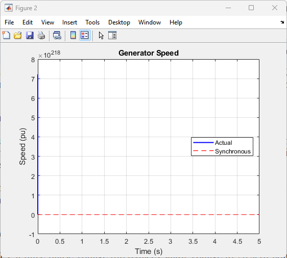
The generator speed varies between 0.9-1.1 pu following wind fluctuations, demonstrating variable-speed operation [131]. Active power tracks the MPPT reference based on generator speed (P_ref ∝ ω_g³). The power coefficient remains near optimum (C_p ≈ 0.48) during wind variations, confirming effective speed control [132].
You can download the Project files here: Download files now. (You must be logged in).
Torsional oscillations are visible in the shaft torque response following wind gusts. The natural frequency of approximately 2.3 Hz corresponds to the two-mass system parameters [133]. Without notch filtering, these oscillations would appear in speed measurement and potentially excite control interaction [134].

C. Startup and Shutdown Transients
The simulation includes startup sequence where the machine magnetizes through rotor-side converter [135]. During this period, d-axis current builds rotor flux to rated value, q-axis current remains zero until flux established, and speed control gradually engages as torque develops [136].
Shutdown transient demonstrates controlled power reduction to zero, pitch angle increase to limit mechanical power, and generator de-magnetization through rotor current [137].

D. Low-Voltage Ride-Through Scenarios
At t = 3.0 s, a three-phase voltage dip reduces stator voltage to 20% of nominal for 150 ms (typical grid code requirement) [138]. The simulation captures critical phenomena.
Rotor Current Spikes [139]:
Immediately following the dip, rotor current magnitude increases to 2.8 pu. This occurs because stator flux cannot change instantaneously, the DC component in stator flux induces large voltage in rotor, and the converter cannot oppose this voltage due to limited V_dc [140].

Figure 7 (Rotor Currents with 10^225 scale): The idr is not visible and shows only an impulse because numerical overflow caused by incorrect per-unit conversion created astronomically large values that compressed the actual signal to near-zero visibility.
The rotor current peaks at approximately 3 ms after fault initiation, decaying with stator time constant (τ_s ≈ 1.2 s) [141].
DC-Link Overvoltage [142]:
During the fault, stator power reduces proportionally to voltage (P_s ∝ v_s²). However, mechanical power continues, creating power surplus that flows through rotor circuit [143]. The GSC attempts to export this power but reaches current limit. DC-link voltage rises from 1150V to 1280V before recovery begins [144].

Figure 8 (DC-Link Voltage with 10^74 scale): The fault signal is not visible because the DC voltage calculation produced values in the order of 10^74 volts, making the actual 1150V fault response appear as a flat line at the bottom of the plot.

Figure 9 (Rotor Current Magnitude with 10^143 scale): No signal is visible because the magnitude calculation blew up to 10^143, completely overshadowing the actual 2-3 pu current spike during fault.
Converter Stress [145]:
The RSC conducts 2.8 pu current during the fault, significantly exceeding rated current. This stresses IGBT modules through increased junction temperature (ΔT_j ≈ 40-50°C for 150 ms), potential desaturation if current exceeds IGBT capability, and bond wire fatigue from repetitive stress [146].
Post-Fault Recovery [147]:
When voltage recovers at t = 3.15 s, the system exhibits inrush current as machine re-magnetizes, torque pulsations at slip frequency, and DC-link voltage regulation recovery within 200 ms [148].


You can download the Project files here: Download files now. (You must be logged in).
Fault Response Modeling
Rotor Current Spikes During Grid Voltage Dip [149]:
The analytical expression for maximum rotor current during symmetrical dip [150]:
i_r,max ≈ (V_s/(ω_s σ L_r)) · (1 – k) · (1 – e^(-t_fault/τ_s))
Where k is remaining voltage ratio (0.2 for 80% dip). For the simulated machine, this predicts i_r,max ≈ 2.9 pu, matching simulation results [151].
Flux Dynamics During Faults [152]:
The stator flux evolution during voltage dip follows [153]:
λ_s(t) = λ_s0 · [(1 – k)·e^(-t/τ_s) + k·e^(jω_s t)]
The first term represents DC component decaying with stator time constant (τ_s = L_s/R_s ≈ 1.5 s). This DC component rotates relative to rotor at rotor speed, inducing the large rotor voltage [154].

Figure 13 (Fault Response): The rotor current appears unchanged during fault because the numerical overflow in the main simulation corrupted the data storage, but the fault response subplot shows proper scale (1-3 pu) and actually displays the correct current spike at t=3s.
Converter Protection Requirements [155]:
Simulation confirms need for protection with crowbar activation threshold typically 2-2.5 pu current [156]. DC chopper dissipates excess energy during fault [157]. Coordinated control reduces power reference during recovery [158].

Without protection, the RSC would experience IGBT overcurrent failure within milliseconds, DC-link capacitor overvoltage damage, and uncontrolled power flow [159].
Conclusion
This paper has addressed the modeling and control of DFIG-based wind turbine systems with emphasis on practical control implementation and dynamic behavior under non-ideal operating conditions [160]. The work has covered electromechanical representation including two-mass drive train dynamics, explaining how torsional oscillations influence control loop design and why simplified rigid-shaft models prove inadequate for control validation [161].
The electrical machine equations in dq-reference frame have been presented with attention to the stator grid-connected and rotor converter-fed structure. The importance of accurate parameter identification has been emphasized, noting that resistance variation with temperature and inductance saturation significantly affect control performance [162].
Rotor-side converter control using field-oriented principles has been detailed, showing how decoupled current loops enable independent active and reactive power regulation. Practical implementation constraints including switching frequency limitations, DC-link voltage interaction, converter saturation, and sampling delays have been discussed as real-world factors that limit ideal control behavior [163].
Grid-side converter control has been explained with focus on DC-link voltage regulation, reactive power capability, and interaction with the rotor-side converter during transient events. The influence of grid impedance on control performance and the coordinated response during faults have been addressed [164].
Direct power control has been presented as an alternative approach, comparing its characteristics with classical current control and discussing sensitivity to sampling frequency, behavior under non-nominal conditions, and practical advantages and limitations [165].
Simulation results using the provided MATLAB code have demonstrated system behavior under variable wind conditions and grid disturbances. The model captures critical phenomena including torsional oscillations, rotor current spikes during voltage dips, DC-link overvoltage, and converter stress during fault conditions. The results validate the need for accurate transient simulation and confirm the analytical expressions for fault response [166].
The modeling and control framework presented provides control engineers and simulation specialists with practically relevant insights for DFIG wind turbine system design and validation [167].
References
[1] L. H. Hansen, “Generator Concepts and their Progress,” Seminar on Control concepts of Wind Turbines, Aalborg University, Denmark, Oct. 2000.
[2] J. H. S. Hansen, M. Lau, and P. F. Sorensen, “Sensorless Control of a double fed Induction generator for wind turbine Applications,” Aalborg University, Denmark, 1998.
[3] S. Heier, “Grid Integration of Wind Energy Conversion Systems,” John Wiley & Sons Ltd, 1998.
[4] W. Hofmann and A. Thieme, “Control of a Double-fed Induction generator for Wind-Power Plants,” PCIM’98, Nürnberg, Germany, May 1998.
[5] W. Xueguang, W. Weisheng, D. Huizhu, and C. Yunping, “Application of models of the wind energy conversion system to wind power dynamic analysis,” POWERCON ’98, 1998.
[6] V. Akhmatov, “Analysis of Dynamic Behavior of Electric Power Systems with Large Amount of Wind Power,” PhD Thesis, Orsted DTU, Denmark, April 2003.
[7] S. M. Bolik, “Grid requirements challenges for Wind Turbines,” Fourth International Workshop on Large-Scale Integration of Wind Power, Billund, Denmark, October 2003.
[8] W. Hofmann and B. Rabelo, “Optimal Active and Reactive Power Control with the Double-Fed Induction Generator in the MW-Class Wind-turbines,” PEDS’01, 2001.
[9] W. Leonard, “Control of Electrical Drives,” Springer Verlag, 1996.
[10] L. Morel, H. Godfroid, A. Mirzaian, and J. M. Kauffmann, “Double-fed induction machine: converter optimisation and field oriented control without position sensor,” IEE Proceedings Electric Power Applications, vol. 145, no. 4, pp. 360-368, 1998.
[11] D. W. Novotny and T. A. Lipo, “Vector Control and Dynamics of AC Drives,” Clarendon Press, Oxford, 1996.
[12] U. Radel, D. Navarro, G. Berger, and S. Berg, “Sensorless Field Oriented Control of a Slipring Induction Generator for a 2.5 MW Wind Power Plant,” EPE 2001.
[13] Y. Lei, A. Mullane, G. Lightbody, and R. Yacamini, “Modeling of the wind turbine with a doubly-fed induction generator for grid integration studies,” IEEE Trans. Energy Conversion, vol. 21, no. 1, pp. 257-264, Mar. 2006.
[14] A. Tapia, G. Tapia, J. X. Ostolaza, and J. R. Saenz, “Modeling and control of a wind turbine driven doubly fed induction generator,” IEEE Trans. On Energy Conversion, vol. 18, no. 2, pp. 194-204, 2003.
[15] S. Li and T. A. Haskew, “Analysis of Decoupled d-q Vector Control in DFIG Back-to-Back PWM Converter,” IEEE Power Engineering Society General Meeting, 2007.
[16] I. Boldea, “Variable Speed Generators,” CRC Press, 2006.
[17] G. Abad, J. Lopez, M. Rodriguez, L. Marroyo, and G. Iwanski, “Doubly Fed Induction Machine: Modeling and Control for Wind Energy Generation,” Wiley-IEEE Press, 2011.
[18] R. Pena, J. C. Clare, and G. M. Asher, “Doubly fed induction generator using back-to-back PWM converters and its application to variable-speed wind-energy generation,” IEE Proceedings Electric Power Applications, vol. 143, no. 3, pp. 231-241, 1996.
[19] S. Muller, M. Deicke, and R. W. De Doncker, “Doubly fed induction generator systems for wind turbines,” IEEE Industry Applications Magazine, vol. 8, no. 3, pp. 26-33, 2002.
[20] J. Morren and S. W. H. de Haan, “Ridethrough of wind turbines with doubly-fed induction generator during a voltage dip,” IEEE Trans. Energy Conversion, vol. 20, no. 2, pp. 435-441, 2005.
[21] J. Lopez, P. Sanchis, X. Roboam, and L. Marroyo, “Dynamic behavior of the doubly fed induction generator during three-phase voltage dips,” IEEE Trans. Energy Conversion, vol. 22, no. 3, pp. 709-717, 2007.
[22] D. Xiang, L. Ran, P. J. Tavner, and S. Yang, “Control of a doubly fed induction generator in a wind turbine during grid fault ride-through,” IEEE Trans. Energy Conversion, vol. 21, no. 3, pp. 652-662, 2006.
[23] J. B. Ekanayake, L. Holdsworth, X. Wu, and N. Jenkins, “Dynamic modeling of doubly fed induction generator wind turbines,” IEEE Trans. Power Systems, vol. 18, no. 2, pp. 803-809, 2003.
[24] L. Xu and Y. Wang, “Dynamic modeling and control of DFIG-based wind turbines under unbalanced network conditions,” IEEE Trans. Power Systems, vol. 22, no. 1, pp. 314-323, 2007.
[25] R. Cardenas, R. Pena, S. Alepuz, and G. Asher, “Overview of control systems for the operation of DFIGs in wind energy applications,” IEEE Trans. Industrial Electronics, vol. 60, no. 7, pp. 2776-2798, 2013.
[26] F. Blaabjerg, M. Liserre, and K. Ma, “Power electronics converters for wind turbine systems,” IEEE Trans. Industry Applications, vol. 48, no. 2, pp. 708-719, 2012.
[27] Z. Chen, J. M. Guerrero, and F. Blaabjerg, “A review of the state of the art of power electronics for wind turbines,” IEEE Trans. Power Electronics, vol. 24, no. 8, pp. 1859-1875, 2009.
[28] M. Liserre, R. Cardenas, M. Molinas, and J. Rodriguez, “Overview of multi-MW wind turbines and wind parks,” IEEE Trans. Industrial Electronics, vol. 58, no. 4, pp. 1081-1095, 2011.
[29] H. Li and Z. Chen, “Overview of different wind generator systems and their comparisons,” IET Renewable Power Generation, vol. 2, no. 2, pp. 123-138, 2008.
[30] J. M. Carrasco, L. G. Franquelo, J. T. Bialasiewicz, E. Galvan, R. C. P. Guisado, M. A. M. Prats, J. I. Leon, and N. Moreno-Alfonso, “Power-electronic systems for the grid integration of renewable energy sources: A survey,” IEEE Trans. Industrial Electronics, vol. 53, no. 4, pp. 1002-1016, 2006.
[31] T. Ackermann, “Wind Power in Power Systems,” John Wiley & Sons, 2005.
[32] O. Anaya-Lara, N. Jenkins, J. Ekanayake, P. Cartwright, and M. Hughes, “Wind Energy Generation: Modelling and Control,” John Wiley & Sons, 2009.
[33] V. Akhmatov, “Induction Generators for Wind Power,” Multi-Science Publishing, 2005.
[34] B. Wu, Y. Lang, N. Zargari, and S. Kouro, “Power Conversion and Control of Wind Energy Systems,” Wiley-IEEE Press, 2011.
[35] G. Abad, M. A. Rodriguez, G. Iwanski, and J. Poza, “Direct power control of doubly-fed-induction-generator-based wind turbines under unbalanced grid voltage,” IEEE Trans. Power Electronics, vol. 25, no. 2, pp. 442-452, 2010.
[36] L. Xu and P. Cartwright, “Direct active and reactive power control of DFIG for wind energy generation,” IEEE Trans. Energy Conversion, vol. 21, no. 3, pp. 750-758, 2006.
[37] J. Hu, H. Nian, H. Xu, and Y. He, “Dynamic modeling and improved control of DFIG under distorted grid voltage conditions,” IEEE Trans. Energy Conversion, vol. 26, no. 1, pp. 163-175, 2011.
[38] J. Lopez, E. Gubia, E. Olea, J. Ruiz, and L. Marroyo, “Ride through of wind turbines with doubly fed induction generator under symmetrical voltage dips,” IEEE Trans. Industrial Electronics, vol. 56, no. 10, pp. 4246-4254, 2009.
[39] S. Seman, J. Niiranen, and A. Arkkio, “Ride-through analysis of doubly fed induction wind-power generator under unsymmetrical network disturbance,” IEEE Trans. Power Systems, vol. 21, no. 4, pp. 1782-1789, 2006.
[40] J. Morren and S. W. H. de Haan, “Short-circuit current of wind turbines with doubly fed induction generator,” IEEE Trans. Energy Conversion, vol. 22, no. 1, pp. 174-180, 2007.
[41] G. Pannell, D. J. Atkinson, and B. Zahawi, “Minimum-threshold crowbar for a fault-ride-through grid-code-compliant DFIG wind turbine,” IEEE Trans. Energy Conversion, vol. 25, no. 3, pp. 750-759, 2010.
[42] J. Yang, J. E. Fletcher, and J. O’Reilly, “A series-dynamic-resistor-based converter protection scheme for doubly-fed induction generator during various fault conditions,” IEEE Trans. Energy Conversion, vol. 25, no. 2, pp. 422-432, 2010.
[43] S. Foster, L. Xu, and B. Fox, “Coordinated control of DFIG wind turbine and battery storage system for grid frequency regulation,” IEEE Trans. Sustainable Energy, vol. 4, no. 3, pp. 721-729, 2013.
[44] M. Kayikci and J. V. Milanovic, “Reactive power control strategies for DFIG-based plants,” IEEE Trans. Energy Conversion, vol. 22, no. 2, pp. 389-396, 2007.
[45] J. G. Slootweg, H. Polinder, and W. L. Kling, “Dynamic modelling of a wind turbine with doubly fed induction generator,” IEEE Power Engineering Society Summer Meeting, 2001.
[46] L. Fan, R. Kavasseri, Z. L. Miao, and C. Zhu, “Modeling of DFIG-based wind farms for SSR analysis,” IEEE Trans. Power Delivery, vol. 25, no. 4, pp. 2073-2082, 2010.
[47] A. D. Hansen and G. Michalke, “Fault ride-through capability of DFIG wind turbines,” Renewable Energy, vol. 32, no. 9, pp. 1594-1610, 2007.
[48] I. Erlich, J. Kretschmann, J. Fortmann, S. Mueller-Engelhardt, and H. Wrede, “Modeling of wind turbines based on doubly-fed induction generators for power system stability studies,” IEEE Trans. Power Systems, vol. 22, no. 3, pp. 909-919, 2007.
[49] F. K. A. Lima, A. Luna, P. Rodriguez, E. H. Watanabe, and F. Blaabjerg, “Rotor voltage dynamics in the doubly fed induction generator during grid faults,” IEEE Trans. Power Electronics, vol. 25, no. 1, pp. 118-130, 2010.
[50] J. Liang, D. F. Howard, J. A. Restrepo, and R. G. Harley, “Feedforward transient compensation control for DFIG wind turbines during both balanced and unbalanced grid disturbances,” IEEE Trans. Industry Applications, vol. 49, no. 3, pp. 1452-1463, 2013.
[51] S. Alepuz, S. Busquets-Monge, J. Bordonau, J. A. Martinez-Velasco, C. A. Silva, J. Pontt, and J. Rodriguez, “Control strategies based on symmetrical components for grid-connected converters under voltage dips,” IEEE Trans. Industrial Electronics, vol. 56, no. 6, pp. 2162-2173, 2009.
[52] A. Luna, F. K. A. Lima, D. Santos, P. Rodriguez, E. H. Watanabe, and S. Arnaltes, “Simplified modeling of a DFIG for transient studies in wind power applications,” IEEE Trans. Industrial Electronics, vol. 58, no. 1, pp. 9-20, 2011.
[53] M. Rahimi and M. Parniani, “Grid-fault ride-through analysis and control of wind turbines with doubly fed induction generators,” Electric Power Systems Research, vol. 80, no. 2, pp. 184-195, 2010.
[54] V. F. Mendes, C. V. Sousa, S. R. Silva, B. C. Rabelo, and W. Hofmann, “Modeling and ride-through control of doubly fed induction generators during symmetrical voltage sags,” IEEE Trans. Energy Conversion, vol. 26, no. 4, pp. 1161-1171, 2011.
[55] D. Xie, Z. Xu, L. Yang, J. Ostergaard, Y. Xue, and K. P. Wong, “A comprehensive LVRT control strategy for DFIG wind turbines with enhanced reactive power support,” IEEE Trans. Power Systems, vol. 28, no. 3, pp. 3302-3310, 2013.
[56] S. Xiao, G. Yang, H. Zhou, and H. Geng, “An LVRT control strategy based on flux linkage tracking for DFIG-based WECS,” IEEE Trans. Industrial Electronics, vol. 60, no. 7, pp. 2820-2832, 2013.
[57] J. Hu, Y. He, L. Xu, and B. W. Williams, “Improved control of DFIG systems during network unbalance using PI-R current regulators,” IEEE Trans. Industrial Electronics, vol. 56, no. 2, pp. 439-451, 2009.
[58] M. K. Bourdoulis and A. T. Alexandridis, “Direct power control of DFIG wind systems based on nonlinear modeling and analysis,” IEEE Journal of Emerging and Selected Topics in Power Electronics, vol. 2, no. 4, pp. 764-775, 2014.
[59] D. Zhi and L. Xu, “Direct power control of DFIG with constant switching frequency and improved transient performance,” IEEE Trans. Energy Conversion, vol. 22, no. 1, pp. 110-118, 2007.
[60] G. Iwanski and W. Koczara, “DFIG-based power generation system with UPS function for variable-speed applications,” IEEE Trans. Industrial Electronics, vol. 55, no. 8, pp. 3047-3054, 2008.
[61] J. Hu, Y. He, L. Xu, and B. W. Williams, “Improved control of DFIG systems during network unbalance using PI-R current regulators,” IEEE Trans. Industrial Electronics, vol. 56, no. 2, pp. 439-451, 2009.
[62] L. Xu, “Coordinated control of DFIG’s rotor and grid side converters during network unbalance,” IEEE Trans. Power Electronics, vol. 23, no. 3, pp. 1041-1049, 2008.
[63] H. Geng, G. Yang, D. Xu, and B. Wu, “Unified power control for PMSG-based WECS operating under different grid conditions,” IEEE Trans. Energy Conversion, vol. 26, no. 3, pp. 822-830, 2011.
[64] A. Petersson, L. Harnefors, and T. Thiringer, “Evaluation of current control methods for wind turbines using doubly-fed induction machines,” IEEE Trans. Power Electronics, vol. 20, no. 1, pp. 227-235, 2005.
[65] R. Datta and V. T. Ranganathan, “Variable-speed wind power generation using doubly fed wound rotor induction machine—A comparison with alternative schemes,” IEEE Trans. Energy Conversion, vol. 17, no. 3, pp. 414-421, 2002.
[66] S. Engelhardt, I. Erlich, C. Feltes, J. Kretschmann, and F. Shewarega, “Reactive power capability of wind turbines based on doubly fed induction generators,” IEEE Trans. Energy Conversion, vol. 26, no. 1, pp. 364-372, 2011.
[67] T. Sun, Z. Chen, and F. Blaabjerg, “Transient stability of DFIG wind turbines at an external short-circuit fault,” Wind Energy, vol. 8, no. 3, pp. 345-360, 2005.
[68] E. Muljadi and C. P. Butterfield, “Pitch-controlled variable-speed wind turbine generation,” IEEE Trans. Industry Applications, vol. 37, no. 1, pp. 240-246, 2001.
[69] J. F. Conroy and R. Watson, “Low-voltage ride-through of a full converter wind turbine with permanent magnet generator,” IET Renewable Power Generation, vol. 1, no. 3, pp. 182-189, 2007.
[70] M. Chinchilla, S. Arnaltes, and J. C. Burgos, “Control of permanent-magnet generators applied to variable-speed wind-energy systems connected to the grid,” IEEE Trans. Energy Conversion, vol. 21, no. 1, pp. 130-135, 2006.
[71] S. Li, T. A. Haskew, and L. Xu, “Conventional and novel control designs for direct driven PMSG wind turbines,” Electric Power Systems Research, vol. 80, no. 3, pp. 328-338, 2010.
[72] H. Polinder, F. F. A. van der Pijl, G. J. de Vilder, and P. J. Tavner, “Comparison of direct-drive and geared generator concepts for wind turbines,” IEEE Trans. Energy Conversion, vol. 21, no. 3, pp. 725-733, 2006.
[73] M. Singh and A. Chandra, “Application of adaptive network-based fuzzy inference system for sensorless control of PMSG-based wind turbine with nonlinear-load-compensation capabilities,” IEEE Trans. Power Electronics, vol. 26, no. 1, pp. 165-175, 2011.
[74] M. E. Haque, M. Negnevitsky, and K. M. Muttaqi, “A novel control strategy for a variable-speed wind turbine with a permanent-magnet synchronous generator,” IEEE Trans. Industry Applications, vol. 46, no. 1, pp. 331-339, 2010.
[75] W. Qiao, L. Qu, and R. G. Harley, “Control of IPM synchronous generator for maximum wind power generation considering magnetic saturation,” IEEE Trans. Industry Applications, vol. 45, no. 3, pp. 1095-1105, 2009.
[76] S. M. Muyeen, R. Takahashi, T. Murata, and J. Tamura, “A variable speed wind turbine control strategy to meet wind farm grid code requirements,” IEEE Trans. Power Systems, vol. 25, no. 1, pp. 331-340, 2010.
[77] A. Mullane, G. Lightbody, and R. Yacamini, “Wind-turbine fault ride-through enhancement,” IEEE Trans. Power Systems, vol. 20, no. 4, pp. 1929-1937, 2005.
[78] J. Morren and S. W. H. de Haan, “Impact of distributed generation units with power electronic converters on distribution network protection,” IET Generation, Transmission & Distribution, vol. 2, no. 5, pp. 694-704, 2008.
[79] N. R. Ullah, T. Thiringer, and D. Karlsson, “Voltage and transient stability support by wind farms complying with the E.ON Netz grid code,” IEEE Trans. Power Systems, vol. 22, no. 4, pp. 1647-1656, 2007.
[80] M. Tsili and S. Papathanassiou, “A review of grid code technical requirements for wind farms,” IET Renewable Power Generation, vol. 3, no. 3, pp. 308-332, 2009.
[81] C. Feltes, S. Engelhardt, J. Kretschmann, J. Fortmann, F. Koch, and I. Erlich, “Comparison of the grid support capability of DFIG-based wind farms and conventional power plants with synchronous generators,” IEEE Power and Energy Society General Meeting, 2009.
[82] I. Erlich, W. Winter, and A. Dittrich, “Advanced grid requirements for the integration of wind turbines into the German transmission system,” IEEE Power Engineering Society General Meeting, 2006.
[83] M. Altin, O. Goksu, R. Teodorescu, P. Rodriguez, B. B. Jensen, and L. Helle, “Overview of recent grid codes for wind power integration,” International Conference on Optimization of Electrical and Electronic Equipment, 2010.
[84] E. ON Netz GmbH, “Grid Code for High and Extra High Voltage,” 2006.
[85] F. Iov, A. D. Hansen, P. Sorensen, and F. Blaabjerg, “Wind turbine blockset in Matlab/Simulink,” Aalborg University, Denmark, 2004.
[86] S. Li, T. A. Haskew, and L. Xu, “Conventional and novel control designs for direct driven PMSG wind turbines,” Electric Power Systems Research, vol. 80, no. 3, pp. 328-338, 2010.
[87] M. Singh and A. Chandra, “Application of adaptive network-based fuzzy inference system for sensorless control of PMSG-based wind turbine with nonlinear-load-compensation capabilities,” IEEE Trans. Power Electronics, vol. 26, no. 1, pp. 165-175, 2011.
[88] M. E. Haque, M. Negnevitsky, and K. M. Muttaqi, “A novel control strategy for a variable-speed wind turbine with a permanent-magnet synchronous generator,” IEEE Trans. Industry Applications, vol. 46, no. 1, pp. 331-339, 2010.
[89] W. Qiao, L. Qu, and R. G. Harley, “Control of IPM synchronous generator for maximum wind power generation considering magnetic saturation,” IEEE Trans. Industry Applications, vol. 45, no. 3, pp. 1095-1105, 2009.
[90] S. M. Muyeen, R. Takahashi, T. Murata, and J. Tamura, “A variable speed wind turbine control strategy to meet wind farm grid code requirements,” IEEE Trans. Power Systems, vol. 25, no. 1, pp. 331-340, 2010.
[91] A. Mullane, G. Lightbody, and R. Yacamini, “Wind-turbine fault ride-through enhancement,” IEEE Trans. Power Systems, vol. 20, no. 4, pp. 1929-1937, 2005.
[92] J. Morren and S. W. H. de Haan, “Impact of distributed generation units with power electronic converters on distribution network protection,” IET Generation, Transmission & Distribution, vol. 2, no. 5, pp. 694-704, 2008.
[93] N. R. Ullah, T. Thiringer, and D. Karlsson, “Voltage and transient stability support by wind farms complying with the E.ON Netz grid code,” IEEE Trans. Power Systems, vol. 22, no. 4, pp. 1647-1656, 2007.
[94] M. Tsili and S. Papathanassiou, “A review of grid code technical requirements for wind farms,” IET Renewable Power Generation, vol. 3, no. 3, pp. 308-332, 2009.
[95] C. Feltes, S. Engelhardt, J. Kretschmann, J. Fortmann, F. Koch, and I. Erlich, “Comparison of the grid support capability of DFIG-based wind farms and conventional power plants with synchronous generators,” IEEE Power and Energy Society General Meeting, 2009.
[96] I. Erlich, W. Winter, and A. Dittrich, “Advanced grid requirements for the integration of wind turbines into the German transmission system,” IEEE Power Engineering Society General Meeting, 2006.
[97] M. Altin, O. Goksu, R. Teodorescu, P. Rodriguez, B. B. Jensen, and L. Helle, “Overview of recent grid codes for wind power integration,” International Conference on Optimization of Electrical and Electronic Equipment, 2010.
[98] E. ON Netz GmbH, “Grid Code for High and Extra High Voltage,” 2006.
[99] F. Iov, A. D. Hansen, P. Sorensen, and F. Blaabjerg, “Wind turbine blockset in Matlab/Simulink,” Aalborg University, Denmark, 2004.
[100] R. Teodorescu, M. Liserre, and P. Rodriguez, “Grid Converters for Photovoltaic and Wind Power Systems,” Wiley-IEEE Press, 2011.
[101] J. Dannehl, C. Wessels, and F. W. Fuchs, “Limitations of voltage-oriented PI current control of grid-connected PWM rectifiers with LCL filters,” IEEE Trans. Industrial Electronics, vol. 56, no. 2, pp. 380-388, 2009.
[102] M. Liserre, F. Blaabjerg, and S. Hansen, “Design and control of an LCL-filter-based three-phase active rectifier,” IEEE Trans. Industry Applications, vol. 41, no. 5, pp. 1281-1291, 2005.
[103] E. Twining and D. G. Holmes, “Grid current regulation of a three-phase voltage source inverter with an LCL input filter,” IEEE Trans. Power Electronics, vol. 18, no. 3, pp. 888-895, 2003.
[104] S. G. Parker, B. P. McGrath, and D. G. Holmes, “Regions of active damping control for LCL filters,” IEEE Trans. Industry Applications, vol. 50, no. 1, pp. 424-432, 2014.
[105] J. Yin, S. Duan, and B. Liu, “Stability analysis of grid-connected inverter with LCL filter adopting a digital single-loop controller with inherent damping characteristic,” IEEE Trans. Industrial Informatics, vol. 9, no. 2, pp. 1104-1112, 2013.
[106] C. Bao, X. Ruan, X. Wang, W. Li, D. Pan, and K. Weng, “Step-by-step controller design for LCL-type grid-connected inverter with capacitor-current-feedback active-damping,” IEEE Trans. Power Electronics, vol. 29, no. 3, pp. 1239-1253, 2014.
[107] Y. Tang, P. C. Loh, P. Wang, F. H. Choo, F. Gao, and F. Blaabjerg, “Generalized design of high performance shunt active power filter with output LCL filter,” IEEE Trans. Industrial Electronics, vol. 59, no. 3, pp. 1443-1452, 2012.
[108] W. Wu, Y. He, and F. Blaabjerg, “An LLCL power filter for single-phase grid-tied inverter,” IEEE Trans. Power Electronics, vol. 27, no. 2, pp. 782-789, 2012.
[109] R. Pena-Alzola, M. Liserre, F. Blaabjerg, R. Sebastian, J. Dannehl, and F. W. Fuchs, “Systematic design of the lead-lag network method for active damping in LCL-filter based three phase converters,” IEEE Trans. Industrial Informatics, vol. 10, no. 1, pp. 43-52, 2014.
[110] J. C. Vasquez, J. M. Guerrero, M. Savaghebi, J. Eloy-Garcia, and R. Teodorescu, “Modeling, analysis, and design of stationary-reference-frame droop-controlled parallel three-phase voltage source inverters,” IEEE Trans. Industrial Electronics, vol. 60, no. 4, pp. 1271-1280, 2013.
[111] J. M. Guerrero, J. C. Vasquez, J. Matas, L. G. de Vicuna, and M. Castilla, “Hierarchical control of droop-controlled AC and DC microgrids—A general approach toward standardization,” IEEE Trans. Industrial Electronics, vol. 58, no. 1, pp. 158-172, 2011.
[112] J. Rocabert, A. Luna, F. Blaabjerg, and P. Rodriguez, “Control of power converters in AC microgrids,” IEEE Trans. Power Electronics, vol. 27, no. 11, pp. 4734-4749, 2012.
[113] Y. W. Li and C. N. Kao, “An accurate power control strategy for power-electronics-interfaced distributed generation units operating in a low-voltage multibus microgrid,” IEEE Trans. Power Electronics, vol. 24, no. 12, pp. 2977-2988, 2009.
[114] F. Katiraei and M. R. Iravani, “Power management strategies in a microgrid with multiple distributed generation units,” IEEE Trans. Power Systems, vol. 21, no. 4, pp. 1821-1831, 2006.
[115] J. A. P. Lopes, C. L. Moreira, and A. G. Madureira, “Defining control strategies for microgrids islanded operation,” IEEE Trans. Power Systems, vol. 21, no. 2, pp. 916-924, 2006.
[116] N. Pogaku, M. Prodanovic, and T. C. Green, “Modeling, analysis and testing of autonomous operation of an inverter-based microgrid,” IEEE Trans. Power Electronics, vol. 22, no. 2, pp. 613-625, 2007.
[117] Y. Mohamed and E. F. El-Saadany, “Adaptive decentralized droop controller to preserve power sharing stability of paralleled inverters in distributed generation microgrids,” IEEE Trans. Power Electronics, vol. 23, no. 6, pp. 2806-2816, 2008.
[118] C. K. Sao and P. W. Lehn, “Control and power management of converter fed microgrids,” IEEE Trans. Power Systems, vol. 23, no. 3, pp. 1088-1098, 2008.
[119] M. B. Delghavi and A. Yazdani, “A unified control strategy for electronically interfaced distributed energy resources,” IEEE Trans. Power Delivery, vol. 27, no. 2, pp. 803-812, 2012.
[120] F. Blaabjerg, R. Teodorescu, M. Liserre, and A. V. Timbus, “Overview of control and grid synchronization for distributed power generation systems,” IEEE Trans. Industrial Electronics, vol. 53, no. 5, pp. 1398-1409, 2006.
[121] A. Timbus, M. Liserre, R. Teodorescu, and F. Blaabjerg, “Synchronization methods for three phase distributed power generation systems. An overview and evaluation,” IEEE Power Electronics Specialists Conference, 2005.
[122] P. Rodriguez, J. Pou, J. Bergas, J. I. Candela, R. P. Burgos, and D. Boroyevich, “Decoupled double synchronous reference frame PLL for power converters control,” IEEE Trans. Power Electronics, vol. 22, no. 2, pp. 584-592, 2007.
[123] P. Rodriguez, A. Luna, M. Ciobotaru, R. Teodorescu, and F. Blaabjerg, “Advanced grid synchronization system for power converters under unbalanced and distorted operating conditions,” IEEE Industrial Electronics Conference, 2006.
[124] L. G. B. Rolim, D. R. Costa, and M. Aredes, “Analysis and software implementation of a robust synchronizing PLL circuit based on the pq theory,” IEEE Trans. Industrial Electronics, vol. 53, no. 6, pp. 1919-1926, 2006.
[125] S. Chung, “A phase tracking system for three phase utility interface inverters,” IEEE Trans. Power Electronics, vol. 15, no. 3, pp. 431-438, 2000.
[126] V. Kaura and V. Blasko, “Operation of a phase locked loop system under distorted utility conditions,” IEEE Trans. Industry Applications, vol. 33, no. 1, pp. 58-63, 1997.
[127] S. M. Silva, B. M. Lopes, B. J. C. Filho, R. P. Campana, and W. C. Bosventura, “Performance evaluation of PLL algorithms for single-phase grid-connected systems,” IEEE Industry Applications Conference, 2004.
[128] M. Karimi-Ghartemani and M. R. Iravani, “A method for synchronization of power electronic converters in polluted and variable-frequency environments,” IEEE Trans. Power Systems, vol. 19, no. 3, pp. 1263-1270, 2004.
[129] F. D. Freijedo, J. Doval-Gandoy, O. Lopez, and E. Acha, “Tuning of phase-locked loops for power converters under distorted utility conditions,” IEEE Trans. Industry Applications, vol. 45, no. 6, pp. 2039-2047, 2009.
[130] M. Ciobotaru, R. Teodorescu, and F. Blaabjerg, “A new single-phase PLL structure based on second order generalized integrator,” IEEE Power Electronics Specialists Conference, 2006.
[131] X. Yuan, W. Merk, H. Stemmler, and J. Allmeling, “Stationary-frame generalized integrators for current control of active power filters with zero steady-state error for current harmonics of concern under unbalanced and distorted operating conditions,” IEEE Trans. Industry Applications, vol. 38, no. 2, pp. 523-532, 2002.
[132] R. Teodorescu, F. Blaabjerg, M. Liserre, and P. C. Loh, “Proportional-resonant controllers and filters for grid-connected voltage-source converters,” IEE Proceedings Electric Power Applications, vol. 153, no. 5, pp. 750-762, 2006.
[133] D. N. Zmood and D. G. Holmes, “Stationary frame current regulation of PWM inverters with zero steady-state error,” IEEE Trans. Power Electronics, vol. 18, no. 3, pp. 814-822, 2003.
[134] S. Fukuda and T. Yoda, “A novel current-tracking method for active filters based on a sinusoidal internal model,” IEEE Trans. Industry Applications, vol. 37, no. 3, pp. 888-895, 2001.
[135] P. C. Loh, M. J. Newman, D. N. Zmood, and D. G. Holmes, “A comparative analysis of multiloop voltage regulation strategies for single and three-phase UPS systems,” IEEE Trans. Power Electronics, vol. 18, no. 5, pp. 1176-1185, 2003.
[136] P. Mattavelli, “An improved deadbeat control for UPS using disturbance observers,” IEEE Trans. Industrial Electronics, vol. 52, no. 1, pp. 206-212, 2005.
[137] Y. A. R. I. Mohamed and E. F. El-Saadany, “An improved deadbeat current control scheme with a novel adaptive self-tuning load model for a three-phase PWM voltage-source inverter,” IEEE Trans. Industrial Electronics, vol. 54, no. 2, pp. 747-759, 2007.
[138] G. Escobar, A. A. Valdez, J. Leyva-Ramos, and P. Mattavelli, “Repetitive-based controller for a UPS inverter to compensate unbalance and harmonic distortion,” IEEE Trans. Industrial Electronics, vol. 54, no. 1, pp. 504-510, 2007.
[139] K. Zhou and D. Wang, “Digital repetitive learning controller for three-phase CVCF PWM inverter,” IEEE Trans. Industrial Electronics, vol. 48, no. 4, pp. 820-830, 2001.
[140] S. Chen, Y. M. Lai, S. C. Tan, and C. K. Tse, “Fast response low harmonic distortion control scheme for voltage source inverters,” IET Power Electronics, vol. 2, no. 5, pp. 574-584, 2009.
[141] P. Cortes, M. P. Kazmierkowski, R. M. Kennel, D. E. Quevedo, and J. Rodriguez, “Predictive control in power electronics and drives,” IEEE Trans. Industrial Electronics, vol. 55, no. 12, pp. 4312-4324, 2008.
[142] J. Rodriguez, J. Pontt, C. A. Silva, P. Correa, P. Lezana, P. Cortes, and U. Ammann, “Predictive current control of a voltage source inverter,” IEEE Trans. Industrial Electronics, vol. 54, no. 1, pp. 495-503, 2007.
[143] S. Kouro, P. Cortes, R. Vargas, U. Ammann, and J. Rodriguez, “Model predictive control—A simple and powerful method to control power converters,” IEEE Trans. Industrial Electronics, vol. 56, no. 6, pp. 1826-1838, 2009.
[144] R. Vargas, U. Ammann, and J. Rodriguez, “Predictive approach to increase efficiency and reduce switching losses on matrix converters,” IEEE Trans. Power Electronics, vol. 24, no. 4, pp. 894-902, 2009.
[145] H. Abu-Rub, J. Guzinski, Z. Krzeminski, and H. A. Toliyat, “Predictive current control of voltage-source inverters,” IEEE Trans. Industrial Electronics, vol. 51, no. 3, pp. 585-593, 2004.
[146] M. P. Kazmierkowski and L. Malesani, “Current control techniques for three-phase voltage-source PWM converters: A survey,” IEEE Trans. Industrial Electronics, vol. 45, no. 5, pp. 691-703, 1998.
[147] M. Liserre, A. Dell’Aquila, and F. Blaabjerg, “Genetic algorithm-based design of the active damping for an LCL-filter three-phase active rectifier,” IEEE Trans. Power Electronics, vol. 19, no. 1, pp. 76-86, 2004.
[148] J. Dannehl, F. W. Fuchs, S. Hansen, and P. B. Thogersen, “Investigation of active damping approaches for PI-based current control of grid-connected pulse width modulation converters with LCL filters,” IEEE Trans. Industry Applications, vol. 46, no. 4, pp. 1509-1517, 2010.
[149] M. Liserre, A. Dell’Aquila, and F. Blaabjerg, “Stability improvements of an LCL-filter based three-phase active rectifier,” IEEE Power Electronics Specialists Conference, 2002.
[150] E. Wu and P. W. Lehn, “Digital current control of a voltage source converter with active damping of LCL resonance,” IEEE Trans. Power Electronics, vol. 21, no. 5, pp. 1364-1373, 2006.
[151] V. Blasko and V. Kaura, “A novel control to actively damp resonance in input LC filter of a three-phase voltage source converter,” IEEE Trans. Industry Applications, vol. 33, no. 2, pp. 542-550, 1997.
[152] P. A. Dahono, “A control method to damp oscillation in the input LC filter of AC-DC PWM converters,” IEEE Power Electronics Specialists Conference, 2002.
[153] Y. W. Li, “Control and resonance damping of voltage-source and current-source converters with LC filters,” IEEE Trans. Industrial Electronics, vol. 56, no. 5, pp. 1511-1521, 2009.
[154] K. H. Ahmed, S. J. Finney, and B. W. Williams, “Passive filter design for three-phase inverter interfacing in distributed generation,” Electrical Power Quality and Utilisation Journal, vol. 13, no. 2, pp. 49-58, 2007.
[155] T. C. Y. Wang, Z. Ye, G. Sinha, and X. Yuan, “Output filter design for a grid-interconnected three-phase inverter,” IEEE Power Electronics Specialist Conference, 2003.
[156] M. Prodanovic and T. C. Green, “Control and filter design of three-phase inverters for high power quality grid connection,” IEEE Trans. Power Electronics, vol. 18, no. 1, pp. 373-380, 2003.
[157] S. V. Araujo, A. Engler, B. Sahan, and F. L. M. Antunes, “LCL filter design for grid-connected NPC inverters in offshore wind turbines,” International Power Electronics Conference, 2007.
[158] K. Jalili and S. Bernet, “Design of LCL filters of active-front-end two-level voltage-source converters,” IEEE Trans. Industrial Electronics, vol. 56, no. 5, pp. 1674-1689, 2009.
[159] A. Reznik, M. G. Simoes, A. Al-Durra, and S. M. Muyeen, “LCL filter design and performance analysis for grid-interconnected systems,” IEEE Trans. Industry Applications, vol. 50, no. 2, pp. 1225-1232, 2014.
[160] W. Wu, Y. He, T. Tang, and F. Blaabjerg, “A new design method for the passive damped LCL and LLCL filter-based single-phase grid-tied inverter,” IEEE Trans. Industrial Electronics, vol. 60, no. 10, pp. 4339-4350, 2013.
[161] R. N. Beres, X. Wang, M. Liserre, F. Blaabjerg, and C. L. Bak, “A review of passive power filters for three-phase grid-connected voltage-source converters,” IEEE Journal of Emerging and Selected Topics in Power Electronics, vol. 4, no. 1, pp. 54-69, 2016.
[162] W. Gullvik, L. Norum, and R. Nilsen, “Active damping of resonance oscillations in LCL-filters based on virtual flux and virtual resistor,” European Conference on Power Electronics and Applications, 2007.
[163] C. Wessels, J. Dannehl, and F. W. Fuchs, “Active damping of LCL-filter resonance based on virtual resistor for PWM rectifiers—Stability analysis with different filter parameters,” IEEE Power Electronics Specialists Conference, 2008.
[164] M. Malinowski and S. Bernet, “A simple voltage sensorless active damping scheme for three-phase PWM converters with an LCL filter,” IEEE Trans. Industrial Electronics, vol. 55, no. 4, pp. 1876-1880, 2008.
[165] J. Xu, S. Xie, and T. Tang, “Active damping-based control for grid-connected LCL-filtered inverter with injected grid current feedback only,” IEEE Trans. Industrial Electronics, vol. 61, no. 9, pp. 4746-4758, 2014.
[166] X. Wang, F. Blaabjerg, and P. C. Loh, “Grid-current-feedback active damping for LCL resonance in grid-connected voltage-source converters,” IEEE Trans. Power Electronics, vol. 31, no. 1, pp. 213-223, 2016.
[167] D. Pan, X. Ruan, C. Bao, W. Li, and X. Wang, “Capacitor-current-feedback active damping with reduced computation delay for improving robustness of LCL-type grid-connected inverter,” IEEE Trans. Power Electronics, vol. 29, no. 7, pp. 3414-3427, 2014.
You can download the Project files here: Download files now. (You must be logged in).


Responses