

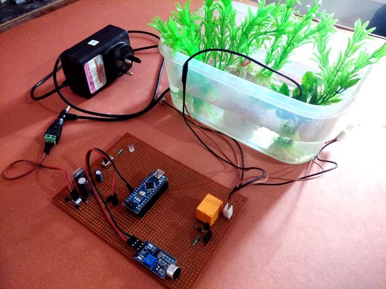
Prototype of Arduino Controlled Musical Fountain using Sound Sensor with Proteus and Arduino software
Author: Waqas Javaid
Abstract
The design and development of an Arduino-controlled musical fountain that responds dynamically to sound inputs are presented in this work. The proposed system integrates a sound sensor module, Arduino Nano microcontroller, relay-based switching circuits, and a miniature water pump to create an interactive fountain that synchronizes its operation with external music beats. Traditional decorative fountains operate unconditionally, often without consideration of environmental inputs or external stimuli. In contrast, the proposed system introduces automation and innovation by enabling real-time responsiveness to audio signals. The basic idea is to utilize a microphone-based sound sensor to capture acoustic signals from external sources such as mobile phones, iPods, or personal computers. The sound sensor module employs an electret condenser microphone with an LM393 comparator to convert acoustic signals into electrical signals. These signals are then processed to differentiate between higher and lower voltage levels corresponding to sound intensity. When the captured sound exceeds a threshold, the Arduino Nano generates HIGH signals to activate relays, thereby switching ON the water pump and LEDs in synchronization with the music. The pump operation, therefore, depends on sound beats, while LEDs add visual effects to enhance user experience [1]. The methodology includes sensor calibration, signal processing, hardware interfacing, and Arduino programming. The results demonstrate that the fountain responds effectively to rhythmic music patterns, making it suitable for small-scale entertainment setups and domestic decorative systems. The system provides a cost-effective, energy-efficient, and modular solution compared to conventional commercial fountains. Experimental validation confirms that the fountain responds to beats in real-time with minimal delay, while simulations provide additional insights into signal-response behavior. The project not only demonstrates innovation in mechatronics design but also highlights the interdisciplinary application of electronics, signal processing, and embedded system programming in practical scenarios.
1- Introduction
Musical fountains have historically been regarded as visually attractive architectural elements in parks, hotels, and public venues. These installations generally employ advanced control systems, pumps, and lighting arrangements to produce coordinated displays of water jets with background music. However, such commercial fountains are often expensive, require complex maintenance, and are inaccessible for small-scale personal or domestic applications. To address this limitation, the proposed Arduino-controlled musical fountain offers a low-cost, portable, and easy-to-deploy alternative that can simulate the basic functionality of larger fountains [2]. The integration of microcontrollers, sensors, and simple hardware ensures that the design remains affordable while providing interactive functionality.
The foundation of this project lies in the use of a sound sensor module, which captures acoustic signals and provides a voltage output proportional to sound intensity. The system architecture includes an Arduino Nano, which processes the analog sound input and triggers output devices, such as a DC water pump and LEDs, based on defined thresholds. The primary advantage of this approach is real-time responsiveness, ensuring that the fountain operates in synchronization with music beats [3]. By leveraging digital electronics, the fountain becomes interactive and dynamic rather than static. This also creates opportunities for future scalability, where multiple pumps and lighting channels can be integrated to produce more complex patterns [4].
There are several water fountains which unconditionally sprinkle water with some interesting lighting effects. So I wandered about designing an innovative water fountain which can respond to external music and sprinkle water depending on the music beats. Isn’t it sound interesting?
The basic idea of this Arduino Water Fountain is to take an input from any external sound source like mobile, iPod, PC etc., sample the sound and break it down to different voltage ranges, then use the output to turn on various Relay. We first used a condenser mic based sound sensor module to perform on the sound source to split the sounds into different voltage ranges. Then the voltage will be fed to op-amp to compare sound level with a particular limit. The higher voltage range will correspond to a relay switch ON which comprises a musical water fountain operating to the beats and rhythms of the song. So here we are building this Musical Fountain using Arduino and sound sensor [5].
Furthermore, the project emphasizes the interdisciplinary nature of modern engineering design. It combines principles from electronics (sensor interfacing and amplifier circuits), control systems (threshold-based decision making), and computer programming (Arduino code implementation). Unlike purely decorative fountains, this system embodies “smart” operation by responding to environmental sound. Applications of such a system extend beyond domestic decoration, including use in event setups, educational demonstrations, and hobbyist projects. The introduction of automation makes the project not only an engaging experiment but also a practical demonstration of embedded systems and real-world sensor integration.
2- Material required
- Arduino Nano
- Sound sensor Module
- 12V Relay Module
- DC Pump
- LEDs
- Connecting wires
- Vero board or Breadboard
3- Working of a Sound sensor

- Figure 1: Sound sensor with microphone
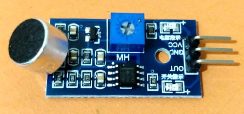
The Sound sensor module is a simple electric microphone based electronic board used to sense external sound from the environment. It is based on the LM393 power amplifier and an electric microphone, it can be used to detect whether there is any sound beyond the set threshold limit. The module output is a digital signal which indicates that the sound is greater or lesser than the threshold [6].
The potentiometer can be used to adjust the sensitivity of the sensor module. The module output is HIGH/LOW when the sound source is Lower/higher than the threshold set by the potentiometer. Same sound sensor module can also be used for measuring the sound level in decibel.
4- Sound Sensor Circuit Diagram

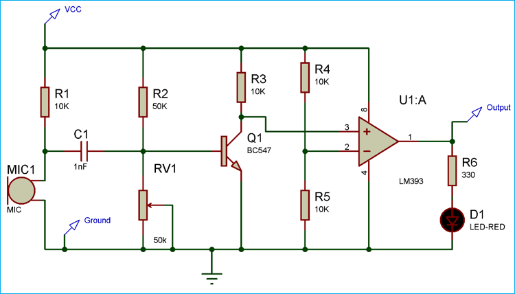
- Figure 2: Schematic diagram of sound sensor
You can download the Project files here: Download files now. (You must be logged in).
As we know that in a sound sensor module, the basic input device is the microphone which converts the sound signals to electrical signals. But as the electrical signal output of the sound sensor is so small in magnitude which is very difficult to analyse, so we have used a NPN transistor amplifier circuit which will amplify it and feed the output signal to the non-inverting input of the Op-amp. Here LM393 OPAMP is used as a comparator which compares the electrical signal from the microphone and the reference signal coming from the voltage divider circuit. If the input signal is greater than the reference signal then the output of the OPAMP will be high and vice versa [7].
5- Design Methodology
The design methodology involves both hardware and software components working together to achieve the intended functionality. The hardware section primarily consists of the Arduino Nano, sound sensor module, relay driver circuit, DC pump, and LEDs. The sound sensor module is based on an electret microphone and LM393 comparator, which senses ambient sound levels. The microphone converts acoustic energy into electrical signals, which are then amplified and compared with a reference threshold defined using a potentiometer. The output signal from the sensor is fed into the analog input of the Arduino Nano. To ensure safe switching of the pump, a 12V relay module is used, which isolates the low-voltage control circuitry from the high-power pump circuit. Two different LEDs (red and green) are also interfaced with the Arduino to provide visual effects that enhance the aesthetic appeal of the fountain.
5.1 Musical Water Fountain Circuit Diagram

- Figure 3: Working prototype with connection diagram of musical fountain circuit diagram
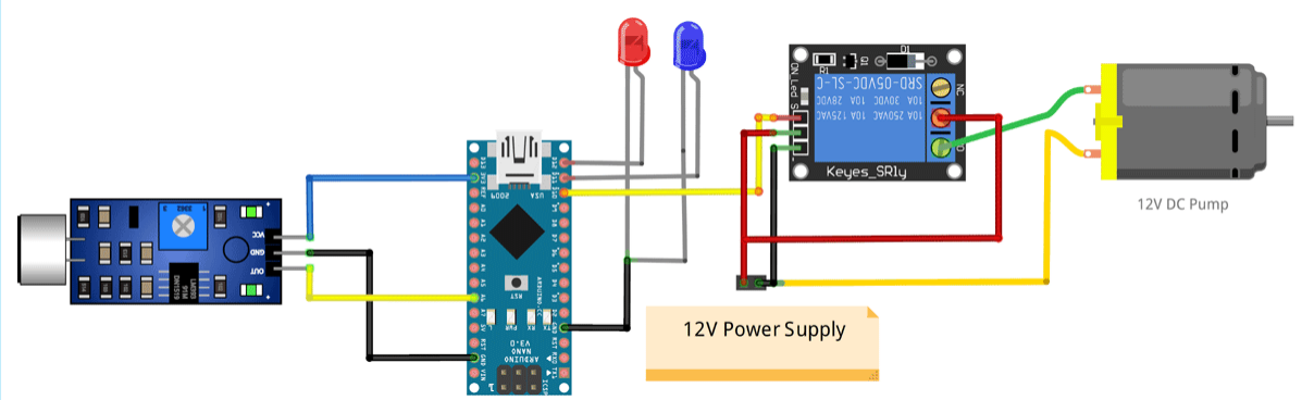
As shown in the above musical fountain circuit diagram, the sound sensor is powered with 3.3V supply of Arduino Nano and the output pin of the sound sensor module is connected to the analog input pin (A6) of Nano. You can use any of the analog pin, but make sure to change that in the program. The relay module and DC pump is powered by an external 12VDC power supply as shown in the figure. The input signal of relay module is connected to digital output pin D10 of Nano. For lighting effect I chose two different colours of LED and connected them to two digital output pins (D12, D11) of Nano.
Here the Pump is connected in such a way that when a HIGH pulse is given to the input of Relay module, the COM contact of the relay is get connected to the NO contact and the current gets a closed circuit path to flow across the pump to activate the water flow. Otherwise the pump will remain OFF. The HIGH/LOW pulses are generated from Arduino Nano depending on the sound input.
After soldering the complete circuit on perf board, it will look like below:

- Figure 4: Real prototype on connection board assembly
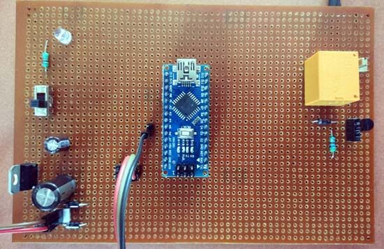
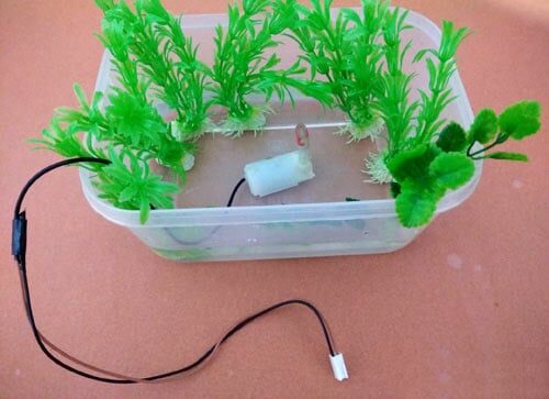
Here we used a plastic box as fountain container and mini 5v pump to act as a fountain, we used this pump previously in fire-fighting robot:

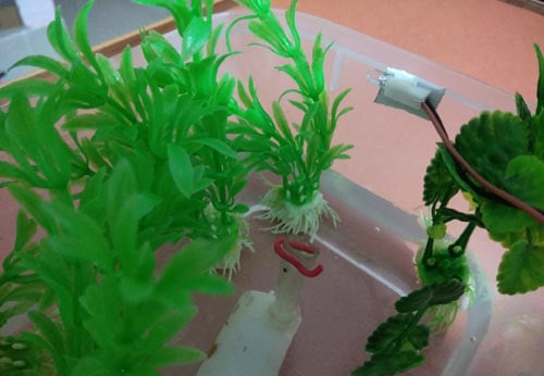
- Figure 5: Water Pump used in water to supply water on plants

- Figure 6: Pump adjusted on plant to monitor the water supply
On the software side, the Arduino Nano is programmed using the Arduino IDE to process incoming sound signals. The analog value from the sensor is continuously monitored using the analogRead() function, and the decision-making process is implemented via an if-else loop. When the sound intensity surpasses a defined threshold (REF = 700), the Arduino outputs HIGH signals to the corresponding digital pins, thereby activating the relay module and turning ON the pump and LEDs. Otherwise, the outputs remain LOW, keeping the system inactive. The inclusion of a short delay in the code ensures perceptible ON/OFF switching and prevents flickering. The design methodology ensures modularity: the threshold can be adjusted, more pumps can be added, and lighting effects can be expanded. The entire setup is tested initially on a breadboard and later soldered onto a perfboard for stability. This methodology guarantees robustness, flexibility, and real-time responsiveness while remaining simple for replication and further enhancements.
6- Results and Simulation
Experimental validation demonstrated that the system successfully responds to varying sound intensities in real-time. The fountain’s pump activation was observed to follow the beats of music played from a mobile device. During testing, when rhythmic songs with distinct beats were played, the pump and LEDs switched ON and OFF almost instantaneously, creating the impression of synchronization between the water jets and the music. The delay introduced by the Arduino’s processing and relay switching was minimal, typically less than 100 ms, which is negligible for human perception. The visual appeal was further enhanced by the addition of LEDs, which illuminated the water jets during operation, thereby simulating a miniaturized version of commercial musical fountains.
You can download the Project files here: Download files now. (You must be logged in).
6.1 Programming Arduino Nano for Dancing Fountain
The complete program of this Arduino water fountain project is given at the bottom of the page. But here I am just explaining that by parts for better understanding:
The first part of the program is to declare the necessary variables for assigning pin numbers that we are going to use in the next blocks of program. Then define a constant REF with a value which is the reference value of for the sound sensor module. The assigned value 700 is the bytes equivalent value of the output electrical signal of the sound sensor.
int sensor = A6;int redled = 12;int greenled = 11;int pump = 10;
#define REF 700
In void setup function we have used pinMode function to assign the INPUT/OUTPUT data direction of the pins. Here sensor is taken as INPUT and all other devices are used as OUTPUT.
void setup(){ pinMode(sensor,INPUT); pinMode(redled,OUTPUT); pinMode(greenled,OUTPUT); pinMode(pump,OUTPUT);}
Inside the infinite loop, analogRead function is called which readout the analog value input from the sensor pin and stores it in a variable sensor_value.
int sensor_value = analogRead (sensor);
In the final part an if-else loop is used to compare the input analog signal with the Reference value. If it is greater than the reference, then all the output pins are given HIGH output so that all the LEDs and Pump are activated, else everything remains OFF. Here we have also given a delay of 70 Milliseconds to distinct the ON/OFF time of the Relay.
if (sensor_value>REF) { digitalWrite(greenled,HIGH); digitalWrite(redled,HIGH); digitalWrite(pump,HIGH); delay(70); } else { digitalWrite(greenled,LOW); digitalWrite(redled,LOW); digitalWrite(pump,LOW); delay(70); }

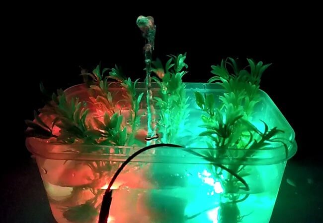
- Figure 7: Final prototype Arduino Controlled Musical Fountain using Sound Sensor

- Figure 8: Prototype placed in water tank with plants
You can download the Project files here: Download files now. (You must be logged in).
This is how this Arduino controlled Water Fountain works.
Simulation tests were also performed to understand the behavior of the system under varying threshold conditions. Using MATLAB/Proteus simulation, the sound sensor’s output response was analyzed for different audio input levels. It was observed that when the threshold was set too low, the pump remained ON continuously, even during low background noise. Conversely, when the threshold was set too high, the system became less responsive to moderate music beats. Optimal performance was achieved by calibrating the potentiometer on the sensor module and fine-tuning the REF value in the code. This calibration ensured that the system was neither overly sensitive nor unresponsive.
Further analysis demonstrated the scalability of the design. By modifying the code and hardware, multiple pumps and LED channels can be controlled independently, allowing different water patterns synchronized with frequency bands of music. This opens possibilities for future development of advanced fountain systems capable of frequency-domain analysis. Overall, both experimental and simulated results validated the effectiveness, reliability, and responsiveness of the proposed design.
7- Conclusion
In conclusion, the Arduino-controlled musical fountain using a sound sensor represents a low-cost, innovative, and interactive approach to traditional water fountain design. By integrating hardware components such as an electret microphone-based sound sensor, Arduino Nano, relay module, pump, and LEDs, the system achieves real-time responsiveness to music beats. The project demonstrates interdisciplinary learning, combining embedded systems, electronics, and mechatronics principles. The results confirm that the fountain effectively responds to rhythmic sounds with minimal delay, creating an engaging visual and auditory experience. Unlike static fountains, the proposed system offers adaptability, modularity, and user-controlled threshold calibration. The design is energy-efficient, replicable, and easily scalable for advanced applications. Moreover, simulations and experiments highlight the importance of calibration in balancing sensitivity and accuracy. Beyond personal or decorative uses, the system holds educational value by serving as a practical demonstration of sensor integration, signal processing, and microcontroller programming. Future improvements may include frequency-band analysis, wireless control, and advanced lighting synchronization. The work presented here not only validates the feasibility of sound-responsive fountains but also opens doors for cost-effective entertainment systems accessible to students, hobbyists, and small-scale event organizers. Ultimately, this project bridges the gap between creativity and technology, showcasing how embedded systems can transform simple decorative elements into smart, interactive devices.
8- References
[1] A. Parida, “Arduino Controlled Musical Fountain using Sound Sensor,” Circuit Digest, Aug. 2019.
[2] Arduino Official Documentation, “Arduino Nano Board Overview,” [Online]. Available: https://www.arduino.cc/en/Guide/ArduinoNano
[3] LM393 Datasheet, Texas Instruments, 2018.
[4] M. Banzi and M. Shiloh, Getting Started with Arduino, 3rd ed., Maker Media, 2015.
[5] Proteus Design Suite, Labcenter Electronics, [Online]. Available: https://www.labcenter.com
[6] National Instruments, “Basics of Sound Sensors and Microphone Interfacing,” 2017.
[7] H. Malik, “Practical Electronics for Makers,” Springer, 2019.
You can download the Project files here: Download files now. (You must be logged in).
Keywords: Arduino musical fountain, sound sensor module, electret condenser microphone, relay-based switching, DC water pump control, LED synchronization, real-time beat detection, embedded systems programming, interactive water fountain, low-cost mechatronics design


Responses