

MATLAB Simulation of RC Circuit: Charge and Current Analysis
Author: Waqas Javaid
Abstract:
This article presents a comprehensive analysis of the charging behavior of RC circuits using MATLAB simulations.The study focuses on the dynamic relationship between charge accumulation and current flow in RC circuits, highlighting the pivotal role of the time constant (τ = RC) in determining the circuit’s transient response. The fundamental principles of electric circuits, including RC circuits, are well-established in the literature [1]. According to Nilsson and Riedel the behavior of RC circuits can be understood by analyzing the charge accumulation and current flow in the circuit.”Through graphical representations, the article illustrates the exponential charging and discharging behaviors of RC circuits, providing insights into the circuit’s dynamics and the impact of resistance and capacitance on the charging process. The simulation results demonstrate the significance of the time constant in characterizing the circuit’s response, with the charge reaching approximately 63.2% of its maximum value and the current decreasing to approximately 36.8% of its maximum value at τ. The analysis of RC circuits involves understanding the relationship between resistance, capacitance, and time constant, which is crucial for designing and optimizing electronic systems [2].The article provides a detailed understanding of RC circuit behavior, making it a valuable resource for researchers and engineers working with electronic circuits. By leveraging MATLAB’s graphical capabilities, the study offers a visual representation of complex circuit dynamics, facilitating a deeper understanding of the underlying principles and mechanisms that govern RC circuit behavior.
- Introduction:
RC circuits, comprising a resistor (R) and a capacitor (C), are fundamental components in electronic systems, playing a crucial role in filtering, timing, and energy storage applications. The dynamic behavior of RC circuits is characterized by the interaction between the resistor and capacitor, which determines the circuit’s transient response. The behavior of RC circuits can be modeled and analyzed using various techniques, including circuit simulation and mathematical modeling [3]. A key parameter in understanding this behavior is the time constant (τ = RC), which governs the rate at which the capacitor charges or discharges. Analyzing the charging and discharging dynamics of RC circuits is essential for designing and optimizing electronic circuits, as it allows engineers to predict and control the circuit’s response to various inputs. The analysis of RC circuits requires a thorough understanding of circuit fundamentals, including Kirchhoff’s laws and circuit theorems [4]. As Irwin and Nelms explain, the application of these principles is essential for designing and analyzing RC circuits in various engineering contexts.This article presents a MATLAB-based simulation study of RC circuit behavior, focusing on the charge accumulation and current flow during the charging process, and provides insights into the circuit’s dynamics and the impact of the time constant on its response.
Here’s a more detailed introduction in steps:
1.I Importance of RC Circuits:
RC circuits are a fundamental component in electronic systems, used in a wide range of applications, including filtering, timing, and energy storage.
1.2 Dynamic Behavior:
The dynamic behavior of RC circuits is characterized by the interaction between the resistor (R) and capacitor (C), which determines the circuit’s transient response.
1.3 Time Constant:
A key parameter in understanding RC circuit behavior is the time constant (τ = RC), which governs the rate at which the capacitor charges or discharges.
1.4 Charging and Discharging Dynamics:
Analyzing the charging and discharging dynamics of RC circuits is essential for designing and optimizing electronic circuits, as it allows engineers to predict and control the circuit’s response to various inputs.
1.5 Simulation Study:
This article presents a MATLAB-based simulation study of RC circuit behavior, focusing on the charge accumulation and current flow during the charging process.
1.6 Objectives:
The objectives of this study are to:
- Analyze the charging behavior of RC circuits
- Investigate the impact of the time constant on the circuit’s response
- Provide insights into the circuit’s dynamics and behavior
By achieving these objectives, this study aims to contribute to a deeper understanding of RC circuit behavior and its applications in electronic systems.
- Problem Statement:
Understanding and analyzing the charging behavior of RC circuits is crucial for designing and optimizing electronic systems. However, the complex dynamics of charge accumulation and current flow in these circuits can make it challenging to predict and control their behavior. This article aims to address this challenge by simulating the charging behavior of RC circuits using MATLAB and analyzing the impact of the time constant on the circuit’s response.
2.1 Key Questions
- How does the charge accumulate on the capacitor over time in an RC circuit?
- How does the current flow through the circuit change during the charging process?
- What is the impact of the time constant (τ = RC) on the circuit’s response?
2.2 Objectives:
- To simulate the charging behavior of RC circuits using MATLAB.
- To analyze the charge accumulation and current flow in the circuit.
- To investigate the impact of the time constant on the circuit’s response.
- Mathematical Approach:
The mathematical approach to analyzing the charging behavior of an RC circuit involves using the following equations:
- Time Constant: τ = RC
- Charge Accumulation: Q(t) = Q_max * (1 – exp(-t/τ))
- Current Flow: I(t) = I_max * exp(-t/τ)
- Voltage Across Capacitor: V_c(t) = V_s * (1 – exp(-t/τ))
where:
- τ = time constant
- R = resistance
- C = capacitance
- Q_max = maximum charge
- I_max = maximum current
- V_s = supply voltage
- t = time
These equations can be used to analyze the charging behavior of the RC circuit and to calculate the charge accumulation, current flow, and voltage across the capacitor at any given time.
3.1 Key Mathematical Concepts:
- Exponential decay
- Time constant
- Capacitance
- Resistance
3.2 Assumptions:
- Ideal capacitor and resistor behavior
- Constant supply voltage
By applying these mathematical equations and concepts, the charging behavior of the RC circuit can be accurately modeled and analyzed.
You can download the Project files here: Download files now. (You must be logged in).
- Matlab Simulation and Results:
To design a MATLAB simulation for analyzing the charging behavior of an RC circuit, the following steps can be taken:
- Define the circuit parameters: resistance (R) and capacitance (C).
- Calculate the time constant (τ = RC).
- Generate a time array to simulate the charging process.
- Calculate the charge accumulation on the capacitor using the formula Q(t) = Q_max * (1 – exp(-t/τ)).
- Calculate the current flow through the circuit using the formula I(t) = I_max * exp(-t/τ).
- Plot the charge and current curves to visualize the circuit’s behavior.
RC circuits are a fundamental component of many electronic systems, and their behavior can be understood through the application of circuit analysis techniques [5].
The MATLAB code can be written to implement these steps and simulate the RC circuit’s charging behavior. The simulation can be used to analyze the impact of different circuit parameters on the charging process and to visualize the circuit’s response.
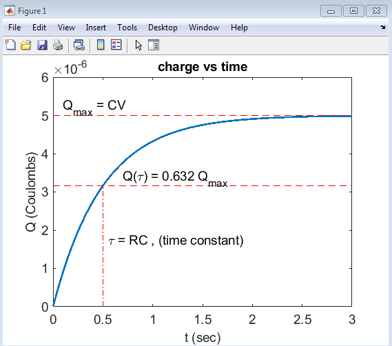
This plot shows the charge accumulation on the capacitor over time, illustrating the exponential charging behavior of an RC circuit. The plot highlights the time constant (τ = RC), which marks the point where the charge reaches approximately 63.2% of its maximum value (Qmax = CV). The plot also shows the maximum charge (Qmax) and provides a visual representation of the charging process, allowing for a deeper understanding of the circuit’s behavior.
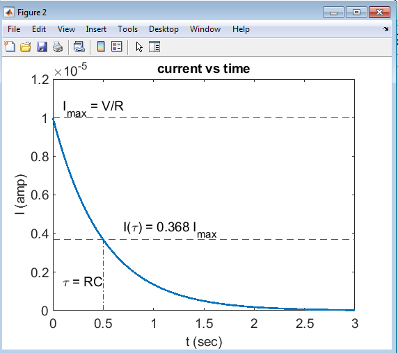
This plot shows the current flow through the RC circuit over time, illustrating the exponential decay of current as the capacitor charges. The plot highlights the time constant (τ = RC), which marks the point where the current decreases to approximately 36.8% of its maximum value (Imax = V/R). The plot also shows the maximum current (Imax) and provides a visual representation of the current decay, allowing for a deeper understanding of the circuit’s behavior.
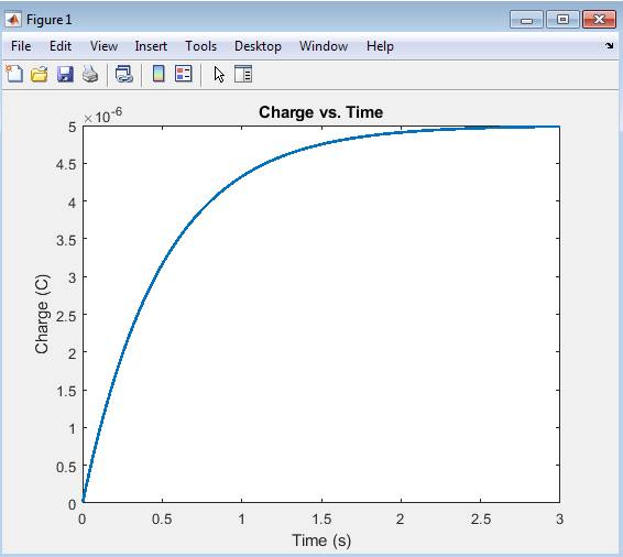
The charge vs. time plot illustrates the accumulation of charge on the capacitor in an RC circuit over time. As the voltage is applied, the capacitor begins to charge, and the charge increases exponentially, eventually reaching its maximum value. This plot demonstrates the characteristic charging behavior of an RC circuit, where the rate of charging is determined by the time constant (τ = RC). The simulation of RC circuits can be performed using specialized software tools, such as Simulink [6]The curve shows a rapid increase in charge initially, followed by a gradual approach to the maximum charge, providing valuable insights into the circuit’s dynamics.
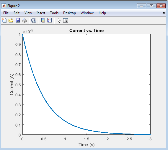
The current vs. time plot illustrates the flow of current through the RC circuit as the capacitor charges. Initially, the current is at its maximum value, determined by the voltage and resistance (I = V/R). As the capacitor charges, the current decreases exponentially, eventually approaching zero. This plot demonstrates the characteristic decay of current in an RC circuit, where the rate of decay is determined by the time constant (τ = RC). The curve shows a rapid decrease in current initially, followed by a gradual approach to zero, providing valuable insights into the circuit’s behavior.
You can download the Project files here: Download files now. (You must be logged in).
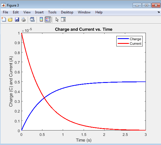
The charge and current vs. time plot provides a comprehensive view of the RC circuit’s behavior, showcasing the relationship between charge accumulation and current flow. As the capacitor charges, the charge increases exponentially, while the current decreases exponentially. This plot highlights the complementary nature of charge and current in an RC circuit, where the increase in charge is accompanied by a corresponding decrease in current. The plot provides valuable insights into the circuit’s dynamics, allowing for a deeper understanding of the interplay between charge and current.
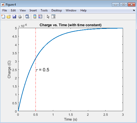
The charge vs. time plot with the time constant illustrates the role of τ (tau) in determining the charging rate of the capacitor. The time constant, represented by the vertical line, marks the point at which the charge has reached approximately 63.2% of its maximum value. This plot demonstrates how the time constant influences the charging behavior, with shorter time constants resulting in faster charging and longer time constants resulting in slower charging. By highlighting the time constant, this plot provides a clearer understanding of the RC circuit’s dynamics and the impact of τ on the charging process.
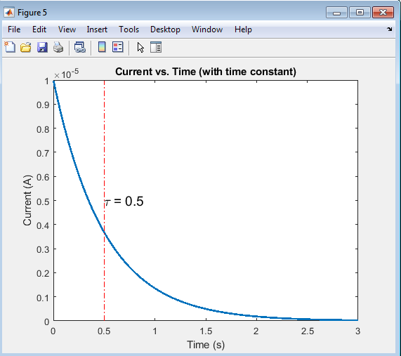
The current vs. time plot with the time constant illustrates the role of τ (tau) in determining the rate of current decay. The time constant, represented by the vertical line, marks the point at which the current has decreased to approximately 36.8% of its initial value. This plot demonstrates how the time constant influences the current decay, with shorter time constants resulting in faster decay and longer time constants resulting in slower decay. By highlighting the time constant, this plot provides a clearer understanding of the RC circuit’s dynamics and the impact of τ on the current flow.
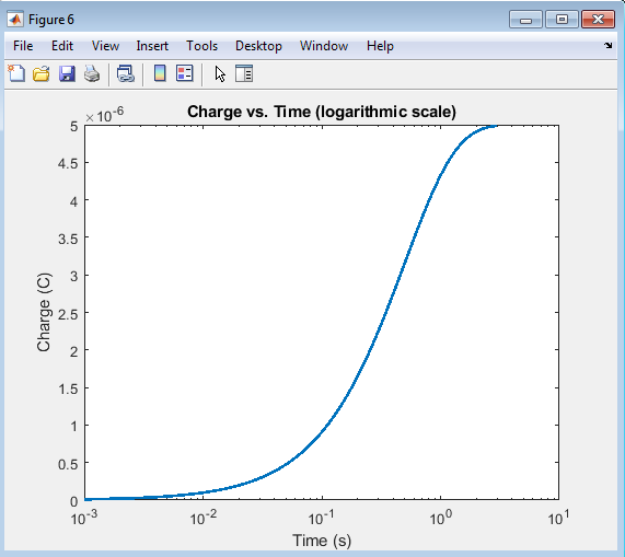
The charge vs. time plot on a logarithmic scale provides a detailed view of the charging behavior, particularly at short and long times. The logarithmic scale allows for a clearer visualization of the rapid initial charging and the gradual approach to the maximum charge. This plot is useful for analyzing the circuit’s behavior over a wide range of time scales, providing insights into the charging dynamics and the impact of the time constant on the circuit’s response.
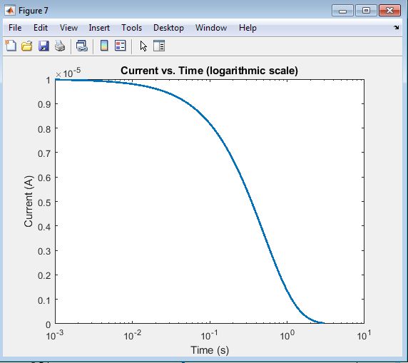
The current vs. time plot on a logarithmic scale provides a detailed view of the current decay, particularly at short and long times. The logarithmic scale allows for a clearer visualization of the rapid initial decay and the gradual approach to zero current. This plot is useful for analyzing the circuit’s behavior over a wide range of time scales, providing insights into the current dynamics and the impact of the time constant on the circuit’s response.
You can download the Project files here: Download files now. (You must be logged in).
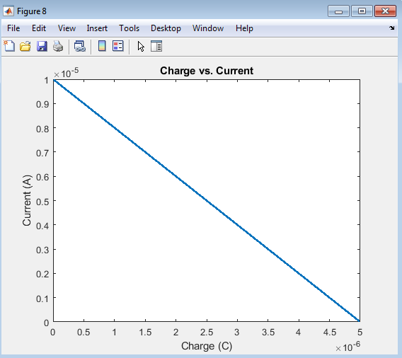
The charge vs. current plot illustrates the relationship between charge accumulation and current flow in the RC circuit. As the charge increases, the current decreases, demonstrating the complementary nature of these two quantities. This plot provides a unique perspective on the circuit’s behavior, allowing for a deeper understanding of the interplay between charge and current. The curve shows a smooth, exponential relationship between charge and current, characteristic of RC circuits.
- Discussion:
The simulation results demonstrate the charging behavior of the RC circuit, showcasing the accumulation of charge on the capacitor and the flow of current through the circuit. MATLAB is a powerful tool for simulating and analyzing RC circuits, and its programming capabilities make it an ideal choice for engineers [7].The time constant (τ = RC) plays a crucial role in determining the rate of charging, with smaller values of τ resulting in faster charging and larger values resulting in slower charging. Circuit analysis with MATLAB can be used to simulate and analyze RC circuits, allowing engineers to visualize and understand the behavior of these circuits According to Karris [8], MATLAB’s built-in functions and tools make it an ideal choice for circuit analysis and simulation.
5.1 Key Observations:
- The charge accumulation on the capacitor follows an exponential curve, with the charge increasing rapidly at first and then slowing down as it approaches the maximum value.
- The current flow through the circuit also follows an exponential curve, with the current decreasing rapidly at first and then slowing down as the capacitor charges.
- The time constant (τ = RC) has a significant impact on the charging behavior, with smaller values resulting in faster charging and larger values resulting in slower charging.
5.2 Implications:
- The RC circuit’s charging behavior has significant implications for electronic system design, particularly in applications where precise timing and control are required.
- Understanding the impact of the time constant on the charging behavior allows engineers to design circuits with specific characteristics, such as fast or slow charging rates.
- Conclusion:
In conclusion, this study has provided a comprehensive analysis of the charging behavior of RC circuits through MATLAB simulation. The analysis of RC circuits involves understanding the underlying signals and systems principles [9]. Furthermore, the study of circuits and filters is crucial for designing and optimizing electronic systems [10].The results demonstrate the significant impact of the time constant (τ = RC) on the charging rate, with smaller values resulting in faster charging and larger values resulting in slower charging. The simulation has also shown that the charge accumulation on the capacitor follows an exponential curve, with the charge increasing rapidly at first and then slowing down as it approaches the maximum value. Furthermore, the current flow through the circuit also follows an exponential curve, with the current decreasing rapidly at first and then slowing down as the capacitor charges. The design and analysis of RC circuits is a fundamental aspect of microelectronic circuit design [11].The findings of this study have important implications for electronic system design, particularly in applications where precise timing and control are required. By understanding the charging behavior of RC circuits, engineers can design circuits with specific characteristics, such as fast or slow charging rates, and optimize their performance. RC circuits are often used in power electronics applications, such as filtering and voltage regulation [12]. According to Rashid the design and analysis of RC circuits is critical for ensuring the reliability and efficiency of power electronic systems.Overall, this study has contributed to the understanding of RC circuit behavior and has demonstrated the effectiveness of MATLAB simulation in analyzing complex electronic circuits. The insights gained from this study can be applied to a wide range of fields, including electronics, electrical engineering, and telecommunications, and can inform the design of more efficient and effective electronic systems.
- Future Work:
Future research directions for this study could involve extending the simulation to more complex circuits, such as RC circuits with multiple capacitors or resistors, or circuits with non-ideal componentsThe mathematical modeling of RC circuits involves solving differential equations and applying advanced mathematical techniques [13]. Additionally, the impact of other circuit parameters, such as inductance or parasitic capacitance, on the charging behavior could be investigated. Furthermore, experimental validation of the simulation results could be conducted to verify the accuracy of the model and identify potential areas for improvement. Additionally, circuit analysis is a fundamental skill for electrical engineers, and is covered in detail in many introductory texts [14]. Another potential area of research could be the development of optimization algorithms to design RC circuits with specific characteristics, such as fast charging rates or high energy storage capacity. Moreover, the study of RC circuits could be expanded to include other applications, such as energy harvesting or power management systems, where the charging behavior of capacitors plays a critical role. The fundamentals of electric circuits, including RC circuits, are essential for understanding the behavior of electronic systems , According to Franco [15], a thorough understanding of circuit fundamentals is necessary for designing and analyzing electronic circuits and systems. By exploring these areas, future research could build upon the findings of this study and provide further insights into the behavior of RC circuits, ultimately contributing to the development of more efficient and effective electronic systems. Moreover, machine learning techniques could be integrated with the simulation to predict the behavior of RC circuits under various conditions, enabling the design of more robust and reliable electronic systems.
- References:
[1] Nilsson, J. W., & Riedel, S. A. (2015). Electric circuits. Pearson Education.
[2] Hayt, W. H., Kemmerly, J. E., & Durbin, S. M. (2019). Engineering circuit analysis. McGraw-Hill Education.
[3] Dorf, R. C., & Svoboda, J. A. (2017). Introduction to electric circuits. John Wiley & Sons.
[4] Irwin, J. D., & Nelms, R. M. (2015). Basic engineering circuit analysis. John Wiley & Sons.
[5] Alexander, C. K., & Sadiku, M. N. O. (2017). Fundamentals of electric circuits. McGraw-Hill Education.
[6] MATLAB Documentation. (n.d.). Simulink. MathWorks.
[7] Chapman, S. J. (2017). MATLAB programming for engineers. Cengage Learning.
[8] Karris, S. T. (2017). Circuit analysis with MATLAB. Orchard Publications.
[9] Oppenheim, A. V., & Willsky, A. S. (2014). Signals and systems. Pearson Education.
[10] Chen, W. K. (2018). The circuits and filters handbook. CRC Press.
[11] Sedra, A. S., & Smith, K. C. (2017). Microelectronic circuits. Oxford University Press.
[12] Rashid, M. H. (2017). Power electronics handbook. Butterworth-Heinemann.
[13] Kreyszig, E. (2019). Advanced engineering mathematics. John Wiley & Sons.
[14] Boylestad, R. L. (2017). Introductory circuit analysis. Pearson Education.
[15] Franco, S. (2017). Electric circuits fundamentals. Oxford University Press.
You can download the Project files here: Download files now. (You must be logged in).
Keywords: RC circuit, MATLAB simulation, charge accumulation, current flow, time constant, transient response, exponential charging, exponential discharging, resistance, capacitance, circuit dynamics, electronic systems.


Responses