

An SNR-improved Transmitter of Delta-sigma Modulation Supported Ultra-High-Order QAM Signal for Fronthaul/WiFi Applications
Author: Waqas Javaid
Abstract—In this paper, we proposed an improved mobile fron- thaul architecture employing the SNR-improved delta-sigma dig- itization scheme and 4-level pulse amplitude modulation (PAM-4) format. Different from traditional 2-bit quantization, this scheme deploys two-fold delta-sigma quantization, which uses 1-bit delta- sigma modulator to quantize the signal, and another 1-bit delta- sigma modulator to quantize the in-band noise. A significant re- duction of the in-band noise can be achieved only applying a differentiator, bringing about a much better noise shaping perfor- mance. Meanwhile, the two 1-bit streams can be combined and transmitted in a PAM-4 manner through an intensity modulation direct detection (IM-DD) channel. We have successfully experi- mentally demonstrated the digitization and transmission of 65536 quadrature amplitude modulation (QAM) baseband orthogonal frequency division multiplexing (OFDM) signal with sampling rate of 1.25 GSa/s over 20-km fiber with standard 10-Gbaud PAM-4 signal, with a signal to noise ratio (SNR) of 57.7 dB. Compared to the conventional 2-bit quantized OFDM scheme, experimental results show that a significant SNR improvement of 17.7 dB has been achieved by the proposed scheme. In addition, we also realized a transmission of 16384-QAM intermediate frequency (IF) signal at the center frequency of 3.5 GHz (with an SNR of 49.6 dB). An improvement of 15.9 dB can also be maintained.
Index Terms—Delta sigma modulation, mobile fronthaul, radio access network, ultra-high-order QAM.
I. Introduction
WITH the increase in demand for high-speed applications, the volume of data usage from end users is growing rapidly, putting forward even higher requirements for mobile fronthaul (MFH). Current MFH networks are mainly operated based on the Common Public Radio Interface (CPRI) pro- tocol, which exhibits excellent tolerance against transmission impairments. However, due to its low spectral efficiency, CPRI becomes the bottleneck of digital MFH to support huge mobile data transmission [1]. As a solution to this issue, the delta-sigma modulation-based MFH architecture has been widely investi- gated [2], [3], owing to its high spectral efficiency and robustness against noise. What’s more, this architecture enables delivery of analog signal through digital ports without any digital-to-analog converters (DACs) [4]. Lots of work have been carried out on delta-sigma modulation to improve the signal-to-noise ratio (SNR), including the employment of high order modulators [5], multiple quantization bits [6] and new feedback structures [7]. Due to the in-band noise, SNR can only reach ∼30 dB and ∼40 dB with 1-bit and 2-bit quantization, respectively, with an oversampling rate (OSR) of 8, which limits further enhancement of spectral efficiency [1], [7].
In order to achieve higher data rate within a fixed bandwidth, it is necessary to send more bits on each symbol [8]. In 802.11ax, the IEEE standard for WiFi 6, 1024-quadrature amplitude mod- ulation (QAM) modulation is selected as the main modulation format [9]. 4096-QAM has already been used in the Qualcomm FastConnect 6900 and 6700 Mobile Connectivity Systems [10]. Furthermore, 802.11be (WiFi 7) is expected to continue upgrad- ing the modulation order, directly using 4096-QAM or higher orders, which will expand the transmission data capacity and challenge the current transmission systems of ultra-high-order QAM. However, some non-ideal factors of analog architectures impede the recovery of high order QAM signal, including the accuracy limitation of DACs and analog-to-digital converters (ADCs), IQ imperfection and nonlinear distortion [11]. Thus, to realize high order QAM with a low-cost architecture is essential and challenging.
In [12], we have proposed an SNR-improved delta-sigma digitization scheme to replace the traditional 2-bit quantization in digital MFH. In this paper, we extend our previous work to bandpass delta-sigma modulators (DSMs), and verify the performance improvement of the proposed scheme over the traditional schemes for other bands. We have demonstrated the digitization and transmission of 65536-QAM baseband or- thogonal frequency division multiplexing (OFDM) signal over 20-km fiber with standard 10-Gbaud 4-level pulse amplitude modulation (PAM-4) signal, with an SNR of 57.7 dB, achieving a significant 17.7 dB improvement compared to PAM-4 (2-bit) quantized scheme. In addition, we also realize the transmission

of 16384-QAM intermediate frequency (IF) signal at the center frequency of 3.5 GHz (with an SNR of 49.6 dB), which shows great robustness over different wireless frequency bands for the 5G and beyond applications.
Rest of this paper is organized as follows. In Section II, we de- scribe the principle of the proposed SNR-improved delta-sigma digitization scheme and design of DSMs for the experimental verifications. In Section III, the experimental setup is given. In Section IV, we present the performance comparison between the proposed SNR-improved delta-sigma digitization scheme and the 2-bit delta-sigma quantization, and demonstrate the transmission of ultra-high-order QAM signal via PAM-4 based intensity modulation direct detection (IM-DD) channel. The impact of channel quality on the transmission performance and the possibility of realizing a low-cost system are discussed in Section V. Finally, Section VI concludes the paper.
II. Principle
A. SNR-Improved Delta-Sigma Digitization Scheme
As the major supporting specifications of modern fronthaul network, CPRI requires a Nyquist ADC with fixed sampling rate. Since the quantization noise of the Nyquist ADC is evenly distributed in the Nyquist zone in the frequency domain, a large number of quantization bits are required to diminish it. Specifi- cally, current CPRI uses one control bit and 15 quantization bits per sample [7], which could be a waste of spectrum resources.
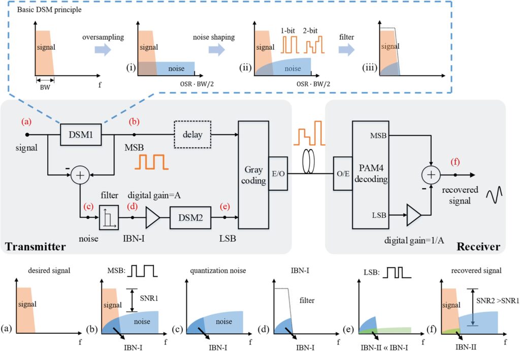
Delta-sigma modulation, as an alternative solution for CPRI, is widely investigated for fronthaul applications [13]–[15]. It can deliver analog signal through digital ports, and the analog signal can be recovered using only a filter, which means no DAC are needed. Different from Nyquist ADCs, delta-sigma modulation oversamples the analog signal to expand its Nyquist zone as shown in Fig. 1(i), so that the quantization noise is spread over a wide frequency range to reduce the in-band noise (IBN). Then noise shaping technique pushes more quantization noise out of the signal band, resulting in an uneven noise floor as shown in Fig. 1(ii). Thus, analog signal can be converted to on-off keying (OOK) or PAM-4 with only one or two quantization bits. At the receiver side, the received signal can be easily retrieved by filtering out the out-of-band noise without DACs as shown in Fig. 1(iii) [1], [2].
In the literature, single-loop modulators have been widely discussed [1], [2], [5], [6]. Recently, DSMs based on MASH structure are also used in MFH [7], [13]. Our proposed scheme is a distributed structure consisting of two DSMs. Similar to the MASH structure [16], cascaded delta delta-sigma (D2S) modulator [17] and double noise-shaped quantizer (DNSQ) [18], we perform noise shaping again on the quantization noise gen- erated by DSM to reduce the quantization noise and increase the SNR of the digitized signal. While, different from the structures [16]–[18], the quantization noise within the signal band gener- ated by the first DSM is extracted by a filter and an amplifier. Then it is used as the input signal to the second DSM and the outputs of the two quantizers are combined by Gray coding. At the receiver side, elimination of noise within the signal band is fulfilled by subtracting the two sequences generated from the two DSMs.
A functional block diagram of the method with the results of key steps marked at the corresponding nodes is shown in Fig. 1. Details of the key steps in the frequency domain are also presented in Fig. 1(a)–(f). Processing procedures of the proposed scheme are described in detail with the explanation of purpose for each step as the following:
step 1: The desired signal shown in Fig. 1(a) is first converted to a 1-bit sequence with DSM1 and the sequence is used as the most significant bit (MSB). As is shown in Fig. 1(b), MSB consists of the desired signal and uneven quantization noise in the frequency domain.
step 2: Then, the quantization noise (the difference between the desired signal and MSB) introduced by DSM1 is fed into a filter to retain the in-band quantization noise IBN-I, as is
shown in Fig. 1(d). In the case when OSR = 8, SNR of the upper branch (SNR1) can only reach ∼30 dB because of the existence of IBN-I.
step 3: Next, IBN-I needs to be digitally amplified to meet the input requirement of DSM2. In subsequent experiments, the gain value is ∼25dB.
step 4: After that, the amplified IBN-I acts as a desired signal in the lower branch, and is converted to another 1-bit sequence by DSM2. The sequence is used as the least significant bit (LSB). As is shown in Fig. 1(e), the newly added IBN-II in LSB is much smaller than IBN-I.
step 5: After the conversions, Gray coding converts the two 1-bit sequences to four levels, which can be delivered to the remote site with standard PAM-4 devices.
step 6: In the receiver, MSB and LSB are recovered by a PAM-4 decoder.
step 7: LSB needs to be attenuated by a specific ratio, which is exactly the magnification ratio in the transmitter. In this paper, the attenuation ratio is ∼25 dB.
step 8: Then, the two 1-bit sequences are fed into a differentiator to eliminate IBN-I, as is shown in Fig. 1(f).
After all these steps, the out-of-band noise is filtered out to recover the desired analog signal with trivial IBN-II left. Since the newly added IBN-II is much smaller than IBN-I, SNR2 in
Fig. 1(f) will be much higher than SNR1 of the MSB. Therefore, low power of IBN-II leads to high SNR of the recovered signals. Specifically, SNR can be determined by three factors, including OSR, parameter setup of DSMs and input signal amplitude: 1) high OSR means that there is less residual quantization noise within the signal band, which results in low power of IBN-II;
2) the parameter setup of DSM has impact on the distribution of quantization noise in the frequency domain. It means that parameters need to be set properly to optimize the noise shaping ability of DSM and push more quantization noise out of the signal band; 3) input signal amplitude can also affect SNR of the digitized signal. Small input levels lead to low SNR, while exceeding the proper input range will cause instability such as overload of quantizers. It is worthy to mention that the circuit
design is critical. The output of MSB and LSB, which limits the SNR of retrieved analog signal in practical implementation, should provide sufficient SNR (>60 dB) to support the ultra-high order modulations.
As a supplementary note, in the transmitter, the filter, amplifier and DSM2 may introduce additional delay to the lower branch. In our experiment, we use offline digital signal processing (DSP) to store and synchronize the sequences. In the practical real- time implementation, a loop-back delay needs to be taken into account for the additional delay of the lower branch as shown in Fig. 1.
B. Simulations and Comparison
To compare the SNR-improved delta-sigma digitization scheme with the traditional delta-sigma quantization schemes, including 1-bit and 2-bit quantization schemes, we analyze the quantization results of baseband OFDM signals of different bandwidths with DSMs working at a fixed rate through sim- ulations.
Fig. 2 shows the results of the three schemes at different OSR. OSR is defined as the ratio of the DSM sampling rate fΔΣ to twice the signal bandwidth BW.
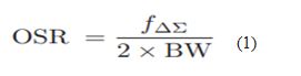
where fΔΣ is fixed at 10 GSa/s and OSR is set at 6, 8, and 10, respectively. Thus, the values of BW are 833MHz, 625MHz and 500MHz through the calculation by (1), respectively.
As is shown in Fig. 2(a), due to the addition of an extra quan- tization bit, compared to the 1-bit quantization scheme, the SNR in the 2-bit scheme is improved by ∼8 dB. The SNR-improved delta-sigma digitization scheme achieves the best and a much higher SNR over the other two. QAM bit error ratio (BER)
waterfall curves are provided in Fig. 2(c), which can be used as the reference between the highest achievable SNR and the maximum supported modulation format. With the maximum supported modulation format according to Fig. 2(c), Fig. 2(b) shows the capacity of OFDM signals with these two schemes when the digital fronthaul system transmits 10-GBaud PAM-4 signals, in which capacity is calculated by (2).
![]()
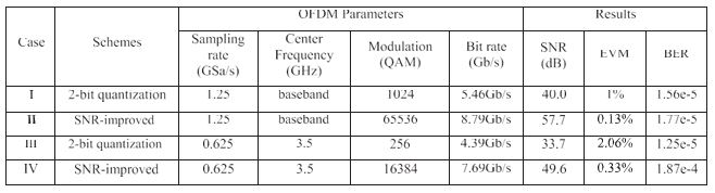
where 900 is the number of data subcarriers and 1024 is fast Fourier transform (FFT) size. Table I shows parameter setups and the results of digitization for OFDM signals with three different bandwidths and OSR. It shows that a maximum in efficiency is obtained for OSR = 8 applying the SNR-improved delta-sigma digitization scheme.
Table II shows the simulation results of baseband signals when OSR = 8 applying 1-bit, 2-bit and the proposed SNR-improved delta-sigma digitization schemes. When OSR = 8, the SNR- improved delta-sigma digitization can achieve an SNR of 57.7 dB, which can support up to 65536-QAM at BER level of 1e-4. However, 2-bit quantization scheme can only provide the SNR of 40 dB, and the corresponding maximum modulation format is 1024-QAM according to Fig. 2(c) at BER level of 1e-4. It means
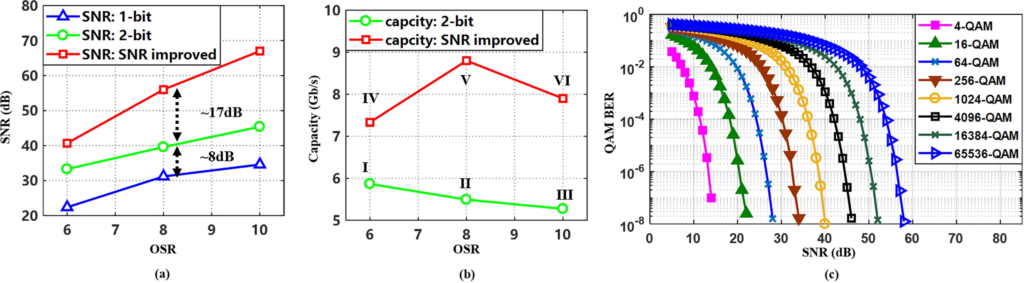
TABLE I
Simulation Parameters and Results of Baseband Signals Through Different Schemes with Different OSR
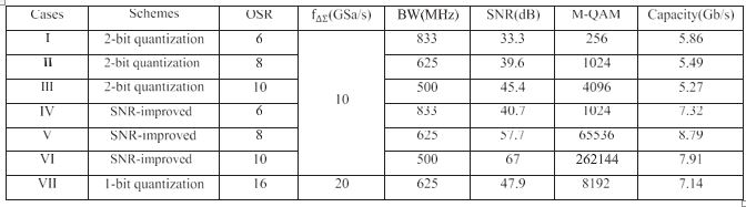
TABLE II
SIMULATION RESULTS OF BASEBAND SIGNALS THROUGH DIFFERENT SCHEMES
BASED ON DELTA-SIGMA MODULATION WITH OSR=8
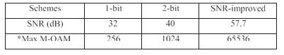
the proposed scheme can increase the capacity per channel by 60%.
Reducing OSR leads to lower SNR and higher bandwidth. As is shown in Fig. 2(a), the 1-bit DSM with OSR = 8 achieves an SNR of 32 dB and an error vector magnitude (EVM) of 2.7%. However, SNR of the 1-bit DSM with OSR = 6 only reaches
∼22 dB with an EVM of 8.3%. According to the requirements of different modulation formats specified by 3GPP release 15 [19], the maximum supported modulation formats of the two DSMs are 256-QAM and 16-QAM, respectively. Therefore, very few works focus on delta-sigma modulation with OSR less than 6. On the contrary, DSMs with OSR = 8 (or higher) are widely investigated in recent works because they achieve a better balance between signal bandwidth and SNR [1], [5], [7], [20].
In addition, to compare the SNR-improved delta-sigma digi- tization scheme with 1-bit quantization scheme, 1-bit modulator with double OSR (OSR = 16) is applied for the quantization of baseband OFDM signals. The parameters and results are listed as case VII in Table I. SNR of 1-bit quantization scheme with OSR = 16 reaches 47.9 dB, supporting up to 8192-QAM. Compared with case V (the SNR-improved scheme, OSR = 8), the SNR improvement with the proposed scheme is still as significant as 9.8 dB.
All the schemes above are tested under a fourth-order DSM based on cascade-of-resonators feedforward (CRFF) structure.
The details will be described in the following section.
You can download the Project files here: Download files now. (You must be logged in).
C. Delta-Sigma Modulators for Baseband Signals and IF Signals
As mentioned before, distribution of quantization noise is determined by the structure and parameters of DSMs. The resonation-based DSM architectures are good solutions to achieve programmable center frequency. A 2N-th-order DSM based on CRFF structure is shown in Fig. 3. It implements a single loop architecture that consists of N resonators and feed forward paths. Each resonator is made up of one Forward-Euler (FE) and one Backward-Euler (BE) integrator [21], [22].
Data flow in the feedback structure is as follows:
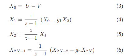
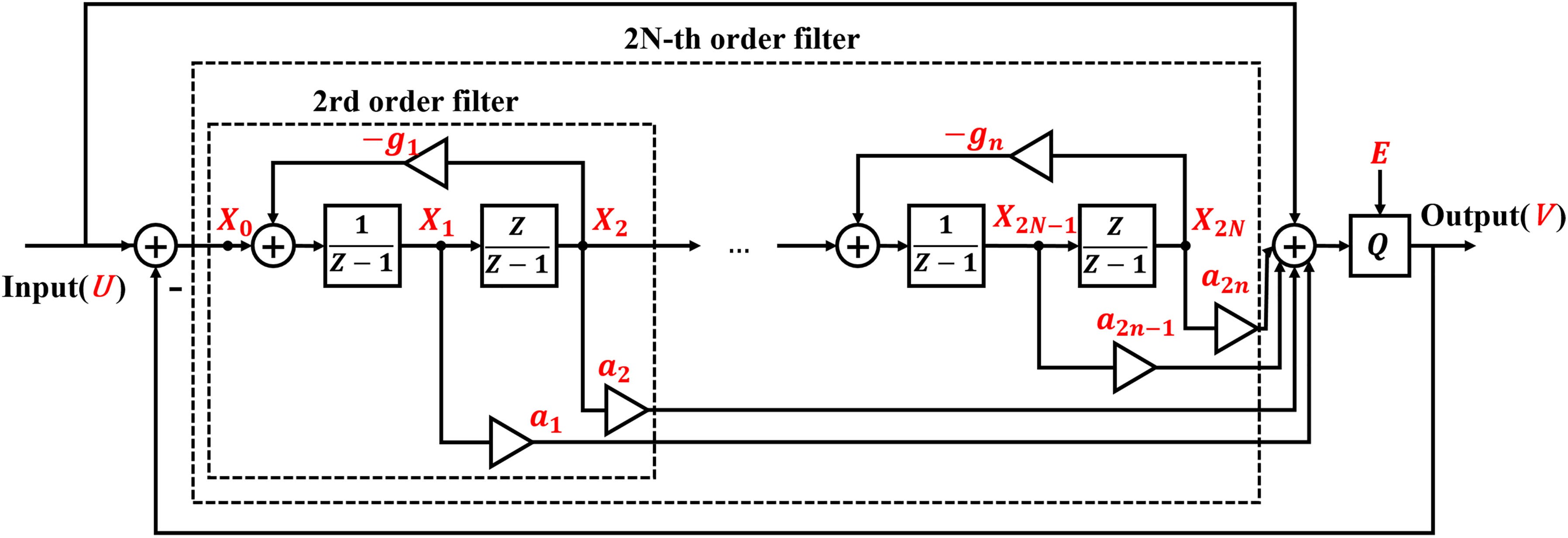
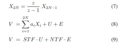
where E represents quantization noise, U and V represent the input and output of the modulator, respectively. an and gn are weight factors and feedback factors shown in Fig. 3, respectively.
Therefore, the noise transfer function (NTF) and signal trans- fer function (STF) of the 2N-th-order CRFF DSM structure are given by:
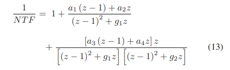
where f ∈ [0, fs/2] is a variable of frequency, and fs represents the sampling rate of DSM.
According to (10), feedback factors gn across the resonators can be set to achieve a desired notch in the NTF of the modulator. A direct path from the input to the adder infers that STF equals to1 [21].
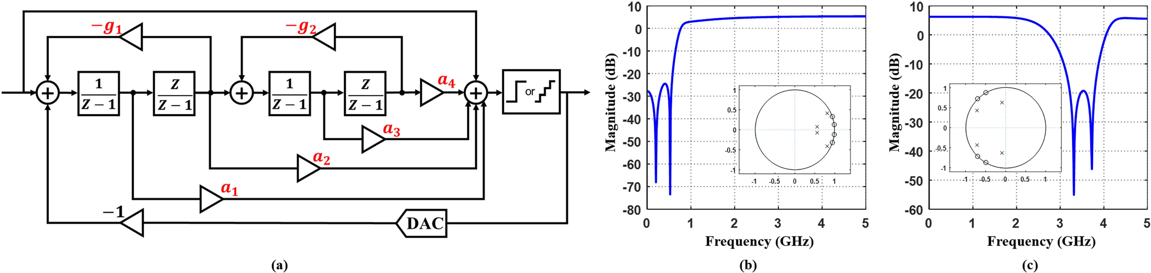
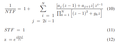
For the baseband signals and IF signals in subsequent ex-periments, the fourth-order DSM based on CRFF structure is employed and its structure is shown in Fig. 4(a). This modula- tor includes a quantizer and four integrators. Although higher order modulators (such as sixth-order) can provide better noise shaping ability, the fourth-order DSM exhibits both good per- formance and better stability [22], [23]. According to (10), NTF of the fourth-order DSM structure is given by:
The specific parameter setups of the two designed DSMs for the following experiments are listed in Table III. Fig. 4 shows the magnitude-frequency response of quantization noise for the two DSMs. The curves are calculated and plotted by substituting Eq. (12) into Eq. (13) with fs = 10 GSa/s. They represent the distribution of quantization noise in the frequency domain. The modulator shown in Fig. 4(b) corresponds to the baseband signals, and Fig. 4(c) corresponds to the IF signals with center frequency at 3.5 GHz. For the baseband analog signals, STF acts as an all-pass filter (STF = 1) and the NTF acts as a
TABLE III
Parameters of DSMs for Baseband Signals and IF Signals
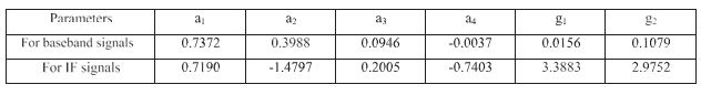
TABLE IV
OFDM Parameters of Baseband and IF Signals Used in Experiments and Results
high-pass filter, so that the quantization noise is distributed more at higher frequencies. While for IF analog signals, NTF acts as a band-stop filter, with less noise accumulated in the signal band. For the zero-poles plot, generally speaking, spreading the zeros can reduce the noise power in the signal band. It can be observed from Fig. 4(b) and (c) that the four zeros are separated on the unit circle and spread over the signal band, which ensures a low in-band noise power.
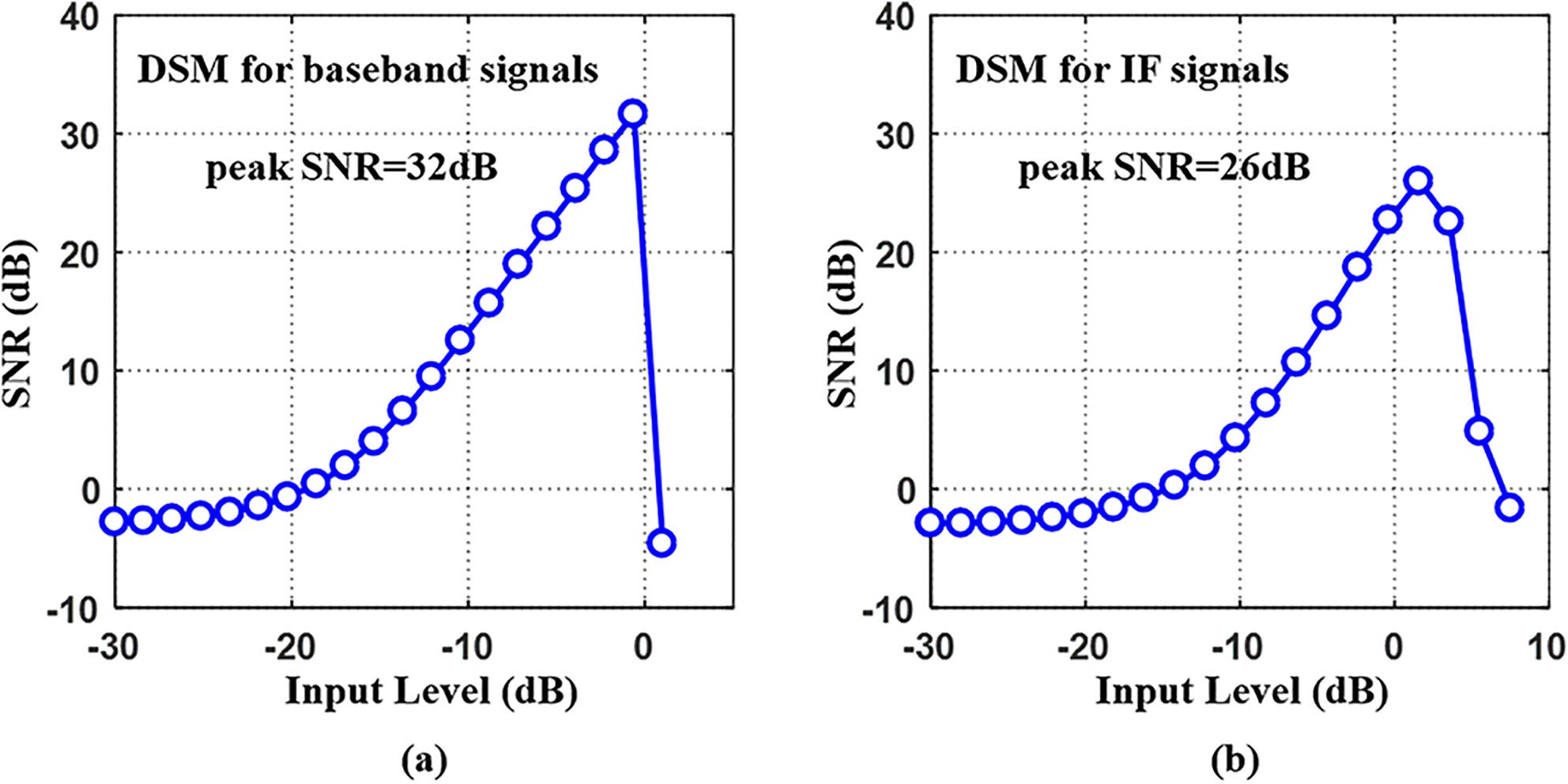
Furthermore, to show the influence of input signal amplitude on DSMs, two designed single-loop DSMs mentioned in this paper with one quantization bit are simulated and tested. SNR value are calculated for various signal input amplitudes and displayed in Fig. 5. Fig. 5 clearly illustrates the impact of input signal level on the SNR performance. An input level of 0 dB represents an analog wave whose peak-to-peak amplitude equals the output range of the modulator. It can be seen that small input levels lead to low SNR, while exceeding the proper input range will cause instability such as overload of quantizers. Therefore, the input signal of DSMs needs to be adjusted to a suitable amplitude level to optimize the SNR of the digitized signal, which is the reason for the adjustment of the IBN-I amplitude in the transmitter (step 3 in principle A).
III. Experimental Setup
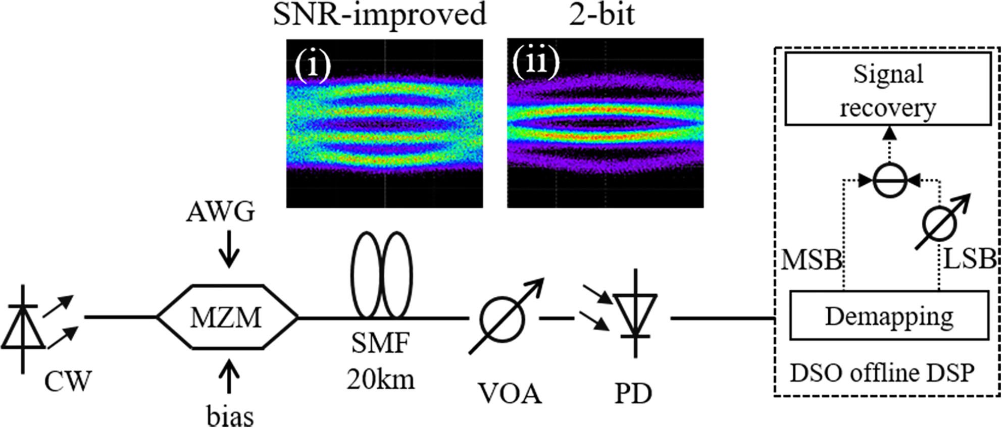
Fig. 6 shows the experimental setup of the 10-Gbaud IM- DD PAM-4 system for performance verification of the SNR- improved delta-sigma digitization-based digital fronthaul ar- chitecture. For comparison, the conventional 2-bit delta-sigma quantization scheme-based digital MFH is also demonstrated. Due to the Gaussian distribution of OFDM signals, the PAM-4 signal after 2-bit digitization has unequal symbol distribution, as is shown in Fig. 6(ii). Different from the 2-bit delta-sigma quantization, eye diagram of the SNR-improved delta-sigma digitization-based PAM-4 signal shown in Fig. 6(i) has even distribution. Table IV lists OFDM parameters of the four cases under test. In the transmitter, the OFDM signal is generated of- fline with FFT size of 1024, in which 900 subcarriers are loaded with data. Sampling rates of baseband and IF OFDM signals are 1.25 GSa/s and 0.625 GSa/s, respectively. With delta-sigma digitization schemes, the OFDM signals are oversampled to 10 GSa/s with an OSR of 8 and quantized to 10-Gbaud PAM-4 sig- nals. After delta-sigma digitization, the delta-sigma modulated bit sequences are generated by an arbitrary waveform generator (AWG Keysight M8195A) working at 60 GSa/s. AWG emulates a 10-Gbaud PAM-4 port, and its output is shown in Fig. 6(i) and (ii) The intensity modulation is fulfilled by an external 1550-nm
laser and a Mach-Zehnder modulator (MZM). 10-Gbaud optical PAM-4 signal is transmitted over 20-km standard single mode fiber (SSMF). At the receiver side, the optical signal is detected by a 40G photodiode (PD). The electrical signal is acquired by an oscilloscope at 60 GSa/s and downloaded for signal decoding and recovery. Then PAM-4 utilizes 5-tap feed forward equal- ization (FFE) for signal recovery. In this experiment, we use offline DSP instead of circuit to achieve signal reconstruction. Offline DSP includes de-mapping, attenuation, differentiation and other general signal recovery procedures. The four-level signal is converted to two 1-bit sequences, and the LSB of them needs to be attenuated corresponding to the amplification ratio in the transmitter. Then the two 1-bit sequences are fed into a differentiator to eliminate the IBN and recover original analog signal with trivial noise left.
You can download the Project files here: Download files now. (You must be logged in).
IV. Experimental Results
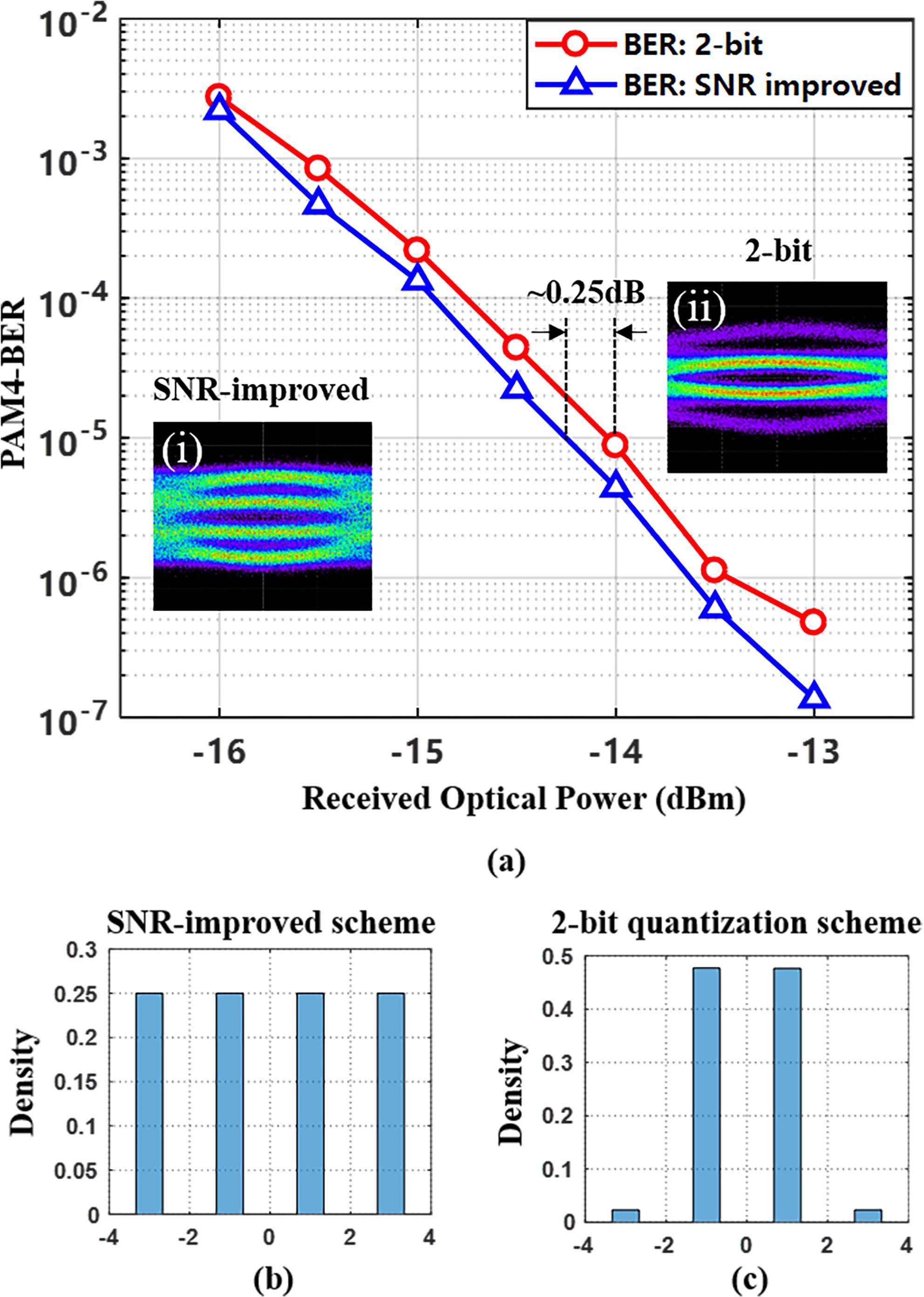
We first conduct an experiment to evaluate the PAM-4 trans- mission performance of the 2-bit quantization scheme and the proposed schemes, which are shown in Fig. 7. As is mentioned before, different from the 2-bit delta-sigma quantization, eye diagram of the SNR-improved delta-sigma digitization-based PAM-4 signal shown in the inset (i) of Fig. 7(a) has even distribution. The distribution of four levels for the schemes in comparison are shown in Fig. 7(b) and (c). In the experiment, the peak-to-peak value of the electrical PAM-4 signals under the two schemes is fixed. In addition, in order to reduce the BER of PAM-4 signals, Gray coding is applied in the SNR-improved quantization scheme in the transmitter, while the 2-bit delta- sigma quantization-based PAM-4 uses natural mapping due to the uneven distribution of four levels. It enables better noise tolerance of the proposed scheme-based PAM-4 signal at the same received optical power (ROP), which is different from the results in [7], as is shown in Fig. 7(a).
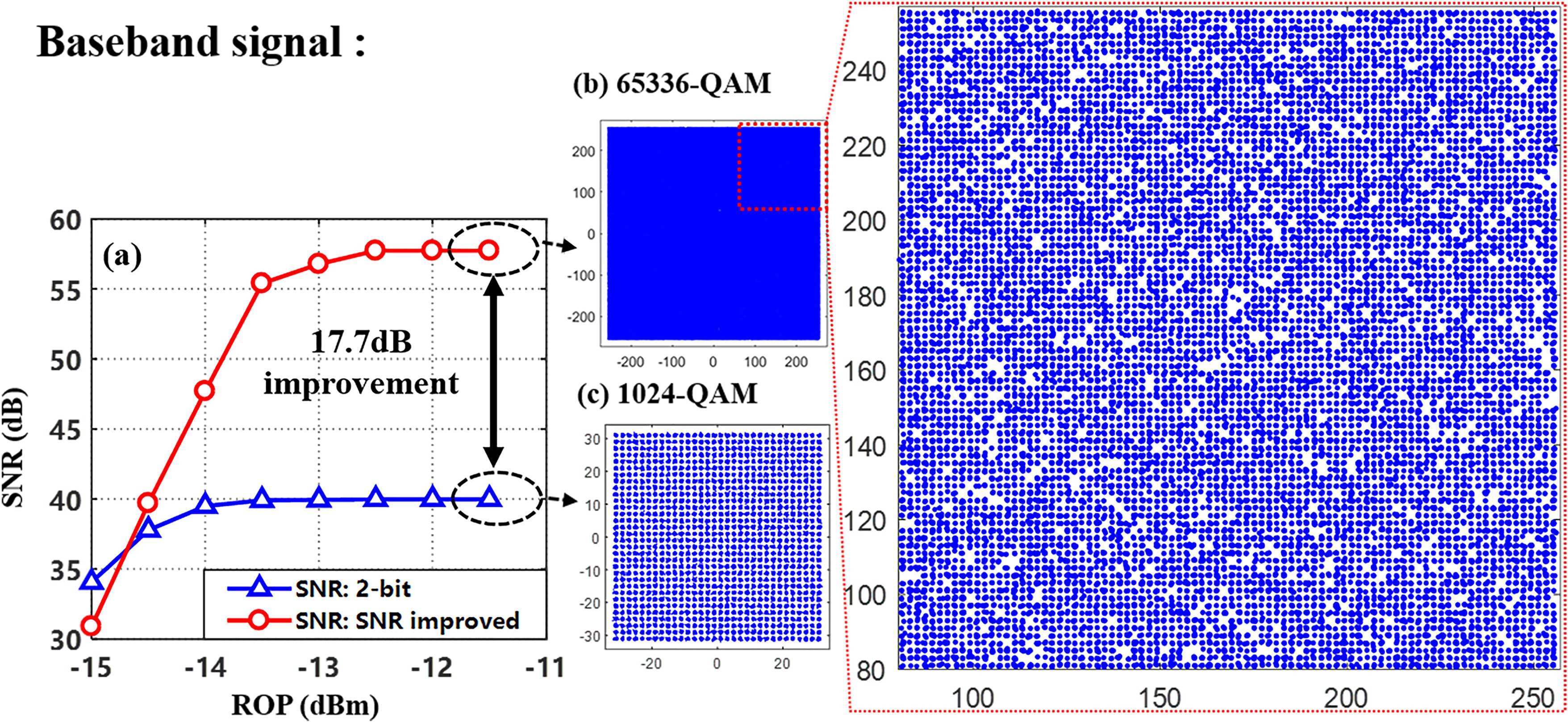
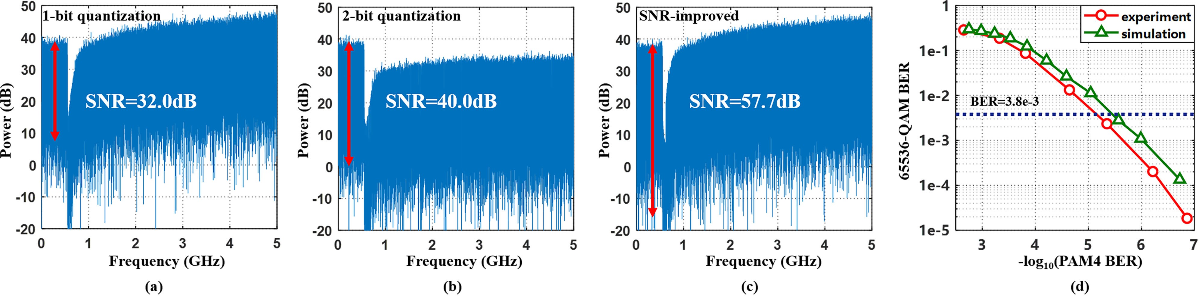
We test the transmission and recovery of 65536-QAM base- band OFDM signal. Fig. 8(a) illustrates the SNR versus ROP performance of the received OFDM signal with 65536-QAM and 1024-QAM modulation format. At ROP = −12 dBm, the SNR-improved delta-sigma digitization achieves an SNR of 57.7 dB, which is sufficient to support 65536-QAM, corresponding to the BER of 1.56e-5, as is shown in Table IV. With the same baud rate of PAM-4 signal, however, SNR of the 2-bit quantization scheme only reaches ∼40 dB, supporting up to 1024-QAM. The SNR improvement is as significant as 17.7 dB. Constellations of the 65536-QAM and 1024-QAM OFDM signal generated by the two approaches at ROP of −12 dBm are also presented in Fig. 8(b) and (c), respectively. The figure on the right is an enlarged partial view of the dotted frame of the 65536-QAM con- stellation diagram. Since the SNR-improved delta-sigma digiti- zation applies 1-bit quantization, the SNR of 65536-QAM sig- nals deteriorates severely under low ROP. Fig. 9 shows the elec- trical spectra of the baseband signals in the three schemes. Com- paring Fig. 9(a) and (b), the addition of an extra quantization bit reduces the quantization noise throughout the Nyquist zone. The proposed scheme deploys two-fold 1-bit quantization, so it can- not reduce the total power of noise. However, owing to the elim- ination of IBN, the proposed scheme achieves much less power of noise within the signal band. It can be seen that the notch of quantization noise in Fig. 9(c) is the lowest, which means there is less residual quantization noise in the band of interest, contributing to a much higher SNR. In the experiments, error- free transmission of 10-Gbaud PAM-4 over 20-km SSMF has been achieved. The impact of BER performance upon the digital fronthaul is also investigated. Fig. 9(d) shows the influence of PAM-4 BER on the BER of received 65536-QAM signal.
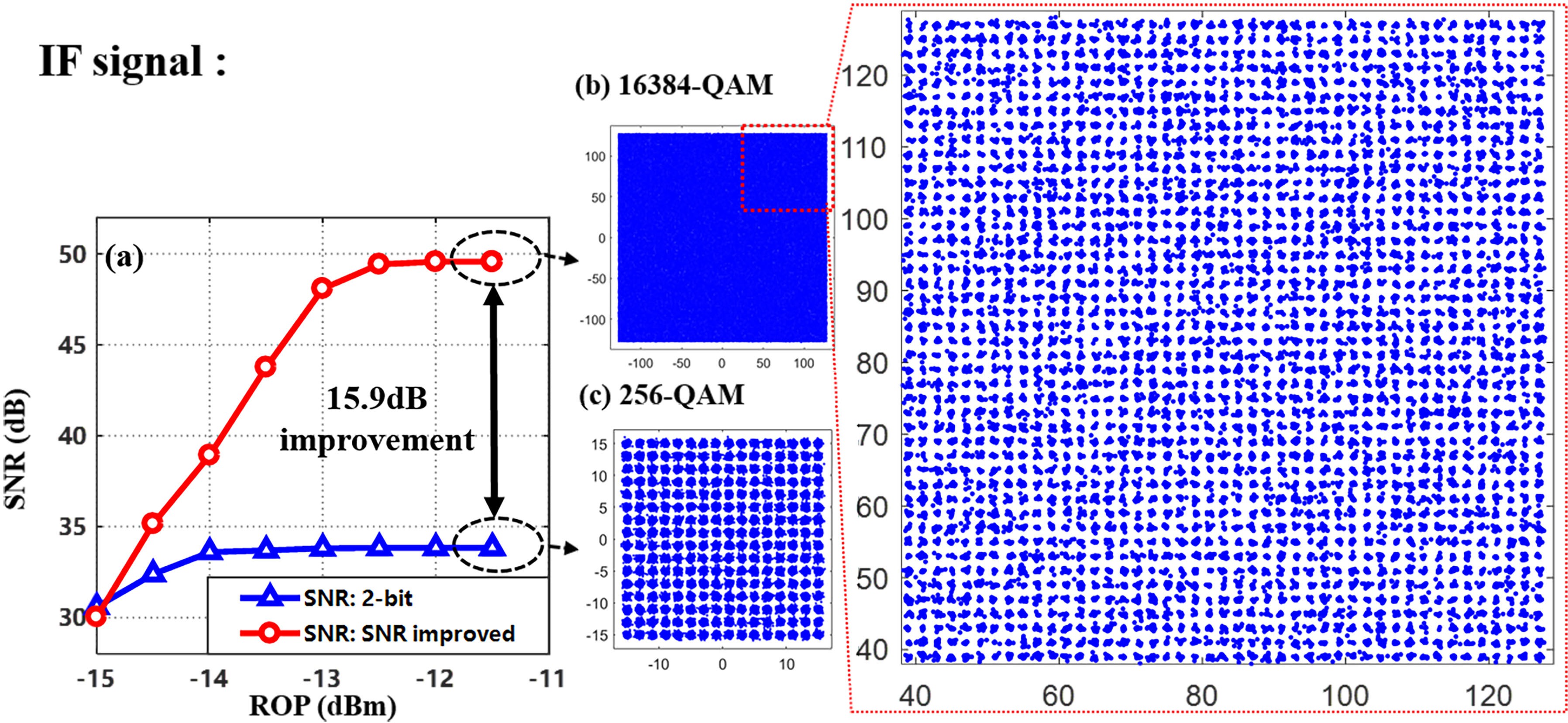
At last, we test the transmission and recovery of an IF signal with 16384-QAM at the center frequency of 3.5 GHz. In case III and case IV, OSR is set to 8, which is consistent with case I and II. Fig. 10 shows the experiment results of case III & IV. Applying the SNR-improved delta-sigma digitization, the best achievable SNR reaches 49.6 dB at ROP = -12 dBm with BER of 1.87e-4, as is shown in Fig. 10(a) and Table IV. Compared to the 2-bit quantization scheme, which can only support 256-QAM, the SNR improvement reaches 15.9 dB. Constellations of 16384-QAM and 256-QAM OFDM signal at ROP of −12 dBm are shown in Fig. 10(b) and (c), respectively. The figure on the right is a partial enlarged view of the dotted frame of the 16384-QAM constellation diagram.
Fig. 11(a) shows the electrical spectrum of the recovered IF signal with 16384-QAM at best performance. It can be seen that signal and noise are separated in the frequency domain,
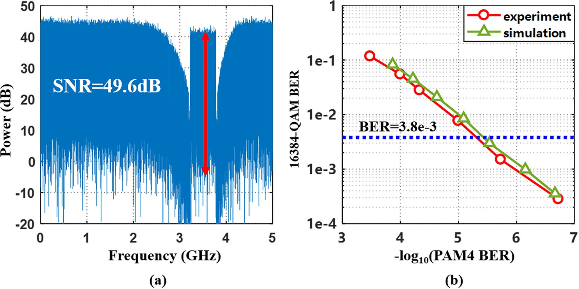
which benefits the signal recovery. Fig. 11(b) shows BER of the IF signal with 16384-QAM as a function of PAM-4 BER. The proposed digital MFH can support 16384-QAM signal at the center frequency of 3.5 GHz without exceeding the 7% forward error correction (FEC) threshold (BER = 3.8e-3)
V. Discussion
A. The Impact of Channel Quality on the Transmission Performance
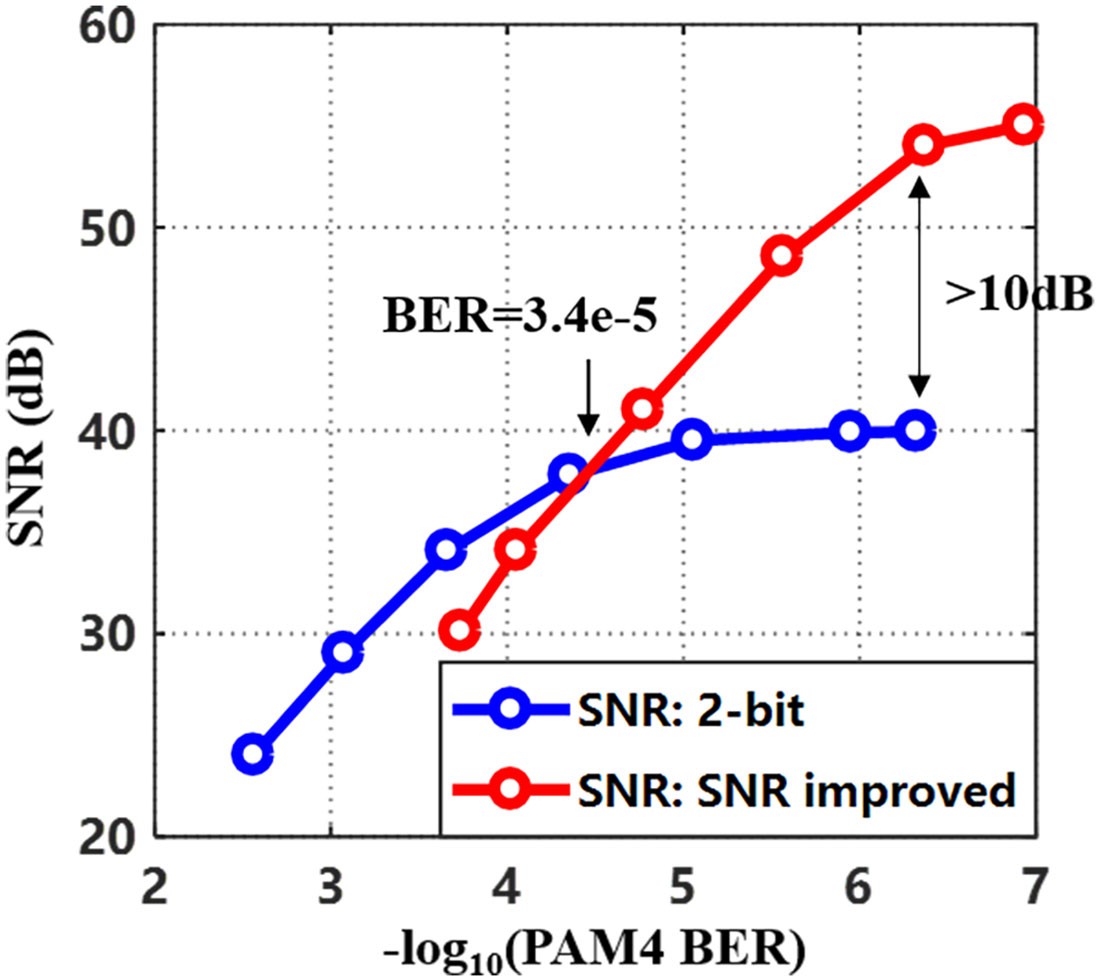
To further illustrate the impact of transmission link quality on the proposed scheme, taking baseband signal as an example, we measure and compare the SNR versus BER performance of received PAM-4 signal in the two different schemes in case I & II, as is shown in Fig. 12. It can be seen that SNR curves of the SNR improved scheme and 2-bit quantization scheme intersect at BER of 3.4e-5. On one hand, the SNR improvement exceeds 10 dB with BER lower than 1e-6. It shows that the proposed scheme can significantly improve the SNR of the desired signal in links with good quality. On the other hand, at higher BER of PAM-4, 2-bit quantization scheme outperforms the proposed scheme. Wrong decision on PAM-4 symbols will bring addi- tional noise to the recovered analog signal, thereby reducing its SNR. With a few error symbols, the IBN introduced by DSM is the main factor limiting SNR. The IBN elimination in this scheme can greatly improve SNR. However, when more error appears, the additional noise is much higher than quantization noise and becomes dominant. In this case, the proposed scheme performs more likely as 1-bit quantization scheme, which shows worse SNR performance than the 2-bit quantization scheme.
In conclusion, the proposed scheme provides significant SNR improvement with low BER of PAM-4 and is not suitable for use in links with poor channel quality.
You can download the Project files here: Download files now. (You must be logged in).
B. The Possibility of Realizing a Low-Cost System
For practical implementation of the proposed scheme, it should be noted that the high-speed electronic devices used in the experiment, including 60 GSa/s DAC and ADC, can be substituted. In the experiment, we used an AWG to generate a 10-GBaud PAM-4 signal and an oscilloscope to acquire electri- cal signal for clock recover (CDR) process. This setup is widely used [1], [5], [7]. In fact, the AWG and oscilloscope are used to emulate optical modules with 10-Gbaud PAM-4.
It is worthy to note that this work is a proof-of-concept demonstration. It can also work at other rate with proper devices. Currently, various transceiver modules are designed for use in PAM-4 transmission at the rate of 50 Gbps and 100 Gbps [24], [25]. For high speed transmission, an IM-DD PAM-4 optical transceiver operating at 100 Gbaud has been demonstrated [26]. Deploying the state-of-the-art electrical PAM-4 multiplexer (e.g., SHF 616 C), which can multiplex four single ended serial non-return-to-zero (NRZ) data streams to one differential PAM- 4 signal with baud rates up to 128 GBaud [27], the achievable bandwidth of OFDM signals can reach up to 8 GHz.
For large-scale user scenarios, there are also many commer- cial devices that can generate multiple channel PAM-4 sig- nals, such as XLINX XCVU29P field-programmable gate array (FPGA) platform, which has 48 PAM-4 transceivers running up to 58Gb/s [28]. Therefore, cooperating with the proposed architecture, the FPGA platform can connect 48 terminals and support ultra-high SNR data transmission services at the same time. It shows strong scalability of the proposed scheme.
Therefore, with low-cost commercial digital devices, it is possible to realize high order QAM with a low-cost architecture. Meanwhile, the use of digital devices makes it easy for integra- tion, which paves the way for fully integrated transmitters and receivers.
VI. Conclusion
In this paper, we demonstrated the digitization and transmis- sion of 65536-QAM OFDM signals over 20-km fiber via PAM-4 IM-DD channel using an improved in-band noise elimination method based on delta-sigma modulation. In our experiment of a 10-Gbaud PAM-4 system with OSR of 8, the SNR-improved delta-sigma digitization scheme can support up to 65536-QAM. The SNR is improved by 17.7 dB compared to the traditional 2-bit scheme. In addition, we also realized a transmission of 16384-QAM IF signal at the center frequency of 3.5 GHz and 15.9 dB SNR improvement has been achieved. Recovery of baseband and IF signals proves superior functionality and flexibility of this architecture, which meets the requirements of 5G fronthaul. It is worthy to mention that the wireless signal bandwidth and data rate can be further increased by using an optical module with higher rate. Meanwhile, the advantages of low cost make the proposed scheme even more promising in the future ultra-high-order modulation communication system.
References
- Wang et al., “Delta-sigma modulation for digital mobile fronthaul enabling carrier aggregation of 32 4G-LTE/30 5G-FBMC signals in a single-λ 10-Gb/s IM-DD channel,” in Proc. Opt. Fiber Commun. Conf. Exhibit., 2016, Paper W1H.2.
- Wang, Z. Jia, L. A. Campos, and C. Knittle, “Real-time demonstration of 5-GSa/s delta-sigma digitization for ultra-wide-bandwidth LTE and 5G signals in next generation fronthaul interface,” in Proc. Eur. Conf. Opt. Commun., 2018, Paper Tu3B.2.
- Wu et al., “Real-Time 4 x 3.5 Gbps sigma delta Radio-over-Fiber for a low-cost 5G C-RAN downlink,” in Proc. Eur. Conf. Opt. Commun., 2018, Paper Tu3B.1.
- Chen et al., “4 × 32-Gbps block-wise QPSK 1200-km SSMF direct detection transmission based on delta-sigma virtual carrier generation,” IEEE Photon. J., vol. 11, no. 6, Dec. 2019, Art. no. 7907407.
- Li et al., “Improving performance of mobile fronthaul architecture employing high order delta-sigma modulator with PAM-4 format,” Opt. Express, vol. 25, no. 1, pp. 1–9, Jan. 2017.
- Wang, Z. Jia, L. A. Campos, L. Cheng, C. Knittle, and G. Chang, “Delta-Sigma digitization and optical coherent transmission of DOCSIS 3.1 signals in hybrid fiber coax networks,” J. Lightw. Technol., vol. 36, no. 2, pp. 568–579, Jan. 2018.
- Bai et al., “Digital mobile fronthaul based on performance enhanced multi-stage noise-shaping delta-sigma modulator,” J. Lightw. Technol., vol. 39, no. 2, pp. 439–447, Jan. 2021.
- McCune, “16,384-QAM Microwave link with 53% linearized- transmitter efficiency, 2.5 watt peak power, and on-air EVM below 1%,” in Proc. IEEE MTT-S Int. Microw. Symp., 2019, pp. 750–753.
- IEEE 80211ax, “The Sixth Generation of Wi-Fi (broadcom.com),” [Online]. Available: https://docs.broadcom.com/doc/80211ax-WP
- Qualcomm FastConnectTM6900 System, [Online]. Available: https://qualcomm.com/media/documents/files/qualcomm-fastconnect-6900-product-brief.pdf
- Chen, J. Cho, A. Adamiecki, and P. Winzer, “16384-QAM transmission at 10 GBd over 25-km SSMF using polarization-multiplexed probabilistic constellation shaping,” in Proc. Eur. Conf. Opt. Commun., 2019, Paper PDP.3.
- Zhong et al., “Experimental demonstration of delta-sigma modulation supported 65536-QAM OFDM transmission for Fronthaul/WiFi applica- tions,” in Proc. Eur. Conf. Opt. Commun., 2021, Paper Th2F.4.
- Li et al., “A 21-GS/s single-bit second-order delta-sigma modulator for FPGAs,” IEEE Trans. Circuits Syst., vol. II, Exp. Briefs, vol. 66, no. 3, 482–486, Mar. 2019.
- Li et al., “Real-time 100-GS/s sigma-delta modulator for all dig- ital radio-over-fiber transmission,” J. Lightw. Technol., vol. 38, no. 2, 386–393, Jan. 2020.
- Wu et al., “Distributed multi-user MIMO transmission using real-time sigma-delta-over-fiber for next generation fronthaul interface,” J. Lightw. Technol., vol. 38, no. 4, pp. 705–713, Feb. 2020.
- R. Norsworthy, R. Schreier, and G. C. Temes, “The design of cascaded ADCs,” in Delta-Sigma Data Converters: Theory, Design, and Simulation, Piscataway, NJ, USA: IEEE, 1997, pp. 193–218, ch6.
- Joseph, L. Tarassenko, and S. Collins, “Analysis and simulation of a cascaded delta delta-sigma modulator,” in Proc. 1999 3rd Int. Conf. Adv. A/D D/A Convers. Techn. Appl. (Conf. Publ. No. 466), 1999, pp. 54–57.
- Kim, C. Han, and N. Maghari, “A 4th-Order continuous-time delta- sigma modulator using 6-bit double noise-shaped quantizer,” IEEE J. Solid-State Circuits, vol. 52, no. 12, pp. 3248–3261, Dec. 2017.
- 3GPP TS 104, “Evolved universal terrestrial radio access (E-UTRA): Base station (BS) radio transmission and reception,” V15.2.0, Mar. 2018 (Release 15).
- Zou et al., “A hierarchical modulation enabled SNR allocable delta- sigma digital mobile fronthaul system,” IEEE Photon. J., vol. 14, no. 1, Feb. 2022, Art. no. 7905406.
- Asghar, R. del Río, and J. M. de la Rosa, “A 0.2-to-2MHz BW, 50-to-86dB SNDR, 16-to-22mW flexible 4th-order ΣΔ modulator with DC-to-44MHz tunable center frequency in 1.2-V 90-nm CMOS,” in Proc. IEEE/IFIP 20th Int. Conf. VLSI System–Chip (VLSI-SoC), 2012, 47–52.
- Schreier and G. C. Temes, Understanding Delta-Sigma Data Convert- ers. New York, NY, USA: Wiley, Nov. 2004.
- Arnaldi, Design of Sigma-Delta Converters in MATLAB/Simulink, Cham, Switzerland: Springer, 2019.
- 400GBASE-FR8 QSFP-DD Optical Transceiver | II-VI [On- line]. Available: https://ii-vi.com/product/400gbase-fr8-qsfp-dd-optical- transceiver/
- FTRJ-8519-1 Specifications (sevensix.co.jp). [Online]. Available: https://www.sevensix.co.jp/wordpress/wp-content/uploads/2021/03/ FTCD4533E2PxM-400G-DR4-QSFP-DD-Product-Spec-RevC2.pdf
- A. Mestre et al., “100-Gbaud PAM-4 intensity-modulation direct- detection transceiver for datacenter interconnect,” in Proc. Eur. Conf. Opt. Commun., 2016, pp. 1–3.
- pdf (shf-communication.com). [Online].
- Virtex UltraScale+ 58G (xilinx.com). [Online]. Available: https: //www.xilinx.com/products/silicon-devices/fpga/virtex-ultrascale-plus-58g.html#advantage
You can download the Project files here: Download files now. (You must be logged in).
Keywords: SNR,Transmitter, Delta-sigma Modulation (DSM), Ultra-High-Order, QAM Signal, Fronthaul, WiFi Applications


Responses