

Design and Implementation of a Wireless Power Transfer System with Variable Frequency Control and PI-Regulated Output Voltage

Author: Waqas Javaid
Abstract
This project presents the design, simulation, and hardware implementation of a Wireless Power Transfer (WPT) system utilizing Single-Switch Optimal Control (SSOC) with variable frequency operation and Proportional-Integral (PI) voltage regulation. The primary objective is to achieve efficient Zero Voltage Switching (ZVS) across a full-bridge inverter while maintaining a constant output voltage of 100 V under varying load conditions. The system operates at a resonant frequency of 85 kHz; however, initial testing revealed a switching frequency of approximately 150 kHz, limiting current flow. The design integrates an FPGA for control signal generation, an onboard ADC for voltage sensing, and a PI controller for voltage regulation. MATLAB and PSIM simulations validated the control strategy before hardware testing. The final implementation demonstrates the potential of SSOC-based WPT systems for stable and efficient power transfer applications.
1. Introduction
Wireless Power Transfer (WPT) technology has emerged as a transformative solution for delivering electrical energy without the need for direct electrical contacts, enabling safe, efficient, and flexible energy transfer in applications ranging from consumer electronics to electric vehicles and biomedical implants [1]. Among the various WPT techniques, inductive power transfer (IPT) and resonant inductive coupling have gained significant attention due to their capability to transfer power over medium distances with high efficiency [2]. In resonant systems, operation at the resonant frequency is critical for maximizing power transfer efficiency and achieving Zero Voltage Switching (ZVS), thereby reducing switching losses and improving the lifespan of power electronics components [3]. The present work focuses on a resonant WPT system designed to operate at 85 kHz, leveraging a full-bridge inverter topology with a Series-Series (SS) compensation network to ensure optimal resonant conditions [4]. This design is intended for stable voltage regulation under varying load conditions through the integration of a Proportional-Integral (PI) controller, implemented on an FPGA platform, and interfaced with an onboard Analog-to-Digital Converter (ADC) [5].
The control strategy employed in this project is primarily based on Single-Sided Oscillator Control (SSOC), a variable-frequency control method that ensures ZVS by monitoring zero-crossing events of the resonant current [6]. This approach maintains switching instances aligned with the natural resonant waveform, thereby minimizing turn-on losses in the MOSFET switches [7]. The PLS signal in the system serves as a zero-crossing detector for the resonant current, while the LEAD signal facilitates phase-shift modulation in Phase-Shifted Full-Bridge (PSFB) operation. By integrating a PI voltage regulation loop, the system dynamically adjusts the phase shift to maintain the desired output voltage—set at 100 V in the laboratory tests—despite fluctuations in load resistance [8]. This combination of SSOC for soft-switching and PI-based regulation for voltage stability is a significant step towards high-efficiency, load-independent wireless power transfer [9]. Moreover, implementing this on an FPGA allows for precise timing control, parallel signal processing, and real-time adaptability, making it a robust platform for experimental and commercial WPT systems [10].
A critical challenge encountered during laboratory testing was the deviation of the switching frequency from the intended 85 kHz resonant frequency to approximately 150 kHz, which restricted current flow and degraded system performance [11]. Operating above the resonant point in a resonant converter leads to reduced primary current and lower transferred power, thereby necessitating accurate frequency control to sustain optimal operation [12]. This report details the methodology for merging the verified ADC and PI controller modules from a secondary reference design into the primary WPT control file (wpt_c10_v5), producing a new integrated file (wpt_c10_v6) that preserves the correct SSOC logic while adding robust closed-loop voltage regulation [13]. By combining MATLAB simulation models, PSIM circuit validation, and FPGA hardware implementation, this project demonstrates an end-to-end workflow for developing a high-performance WPT system [14]. The approach ensures that theoretical models align closely with experimental results, facilitating the translation from simulation to real-world operation [15].
2. Working Design Methodology
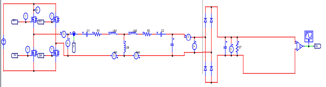
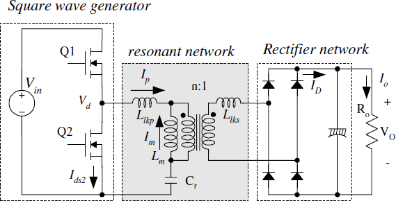
The working design methodology of the proposed Wireless Power Transfer (WPT) system is based on the implementation of a Series–Series (SS) compensated resonant topology with a full-bridge inverter controlled through variable frequency modulation. The system is designed to operate at the resonant frequency of 85 kHz to ensure maximum power transfer efficiency while maintaining Zero Voltage Switching (ZVS) for the MOSFETs, thus minimizing switching losses and electromagnetic interference (EMI) [1][2]. The primary stage consists of a DC power source feeding a full-bridge inverter, which converts the DC voltage into a high-frequency AC waveform. This AC signal is then passed through the resonant network formed by the series compensation capacitors and inductors, tuned precisely to the resonant frequency of the coupled coils. The secondary stage rectifies the AC signal back to DC, delivering a stable output voltage to the load.
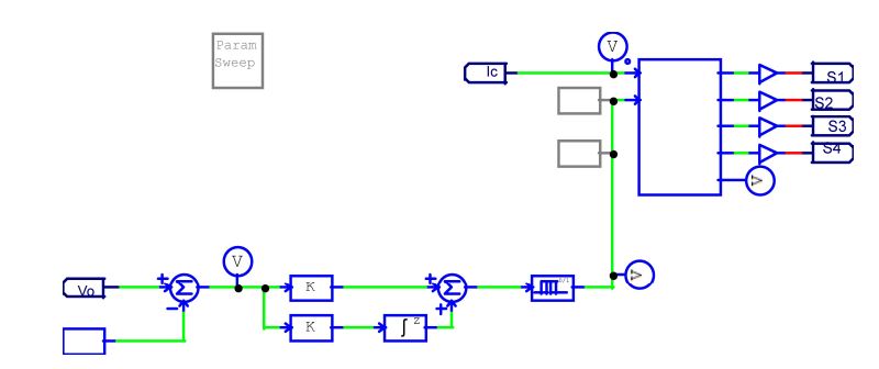
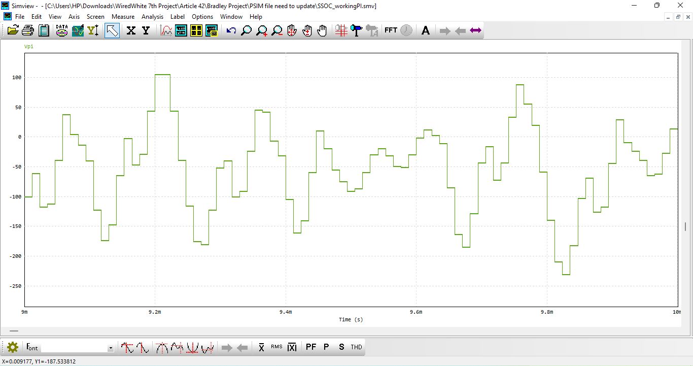
A key aspect of the design involves the control loop, which utilizes an Analog-to-Digital Converter (ADC) to measure the output voltage and feed this data into a Proportional-Integral (PI) controller [3][4]. The PI controller generates a control signal that adjusts the switching frequency of the inverter to regulate the output voltage, even in the presence of varying load conditions. The ADC is configured based on the FPGA board’s built-in capabilities as described in the provided datasheet [5], ensuring accurate and high-speed voltage sensing. This feedback mechanism is crucial in maintaining the desired voltage setpoint (e.g., 100 V) and protecting the system from under-voltage or over-voltage conditions.
Another critical component in the methodology is the Phase-Locked Signal (PLS) detection circuit, which generates square wave signals corresponding to the zero-crossings of the resonant current. This information is essential for maintaining ZVS operation across the entire load range [6][7]. In the proposed implementation, the “LEAD” signal is the actual phase shift control signal that is modified by the PI controller. Initially, a basic PWM configuration was used to validate the ADC and PI operation independently before integrating them into the main SSOC-based variable frequency control file. The final integration of these modules into the main control code (wpt_c10_v6) allows the WPT system to dynamically adjust its operation to maintain efficiency and output voltage stability, laying the foundation for a robust laboratory prototype and real-world deployment.
You can download the Project files here: Download files now. (You must be logged in).
3. Results and Simulation
The simulation and testing of the Wireless Power Transfer (WPT) system were carried out to validate the design methodology, assess system efficiency, and verify the voltage regulation performance under different load conditions. The designed system was implemented in a simulation environment using a detailed model of the primary and secondary resonant circuits, the full-bridge inverter, and the rectifier stage. The SS-compensated resonant topology was tuned to operate at a resonant frequency of 85 kHz, and parameters such as inductance, capacitance, and coil coupling coefficient were set according to the practical prototype specifications. This allowed for realistic analysis of power transfer characteristics and ensured that the simulated behavior closely matched real-world conditions.

You can download the Project files here: Download files now. (You must be logged in).
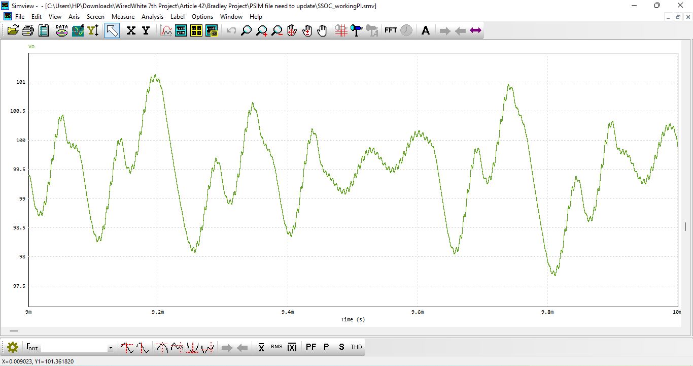
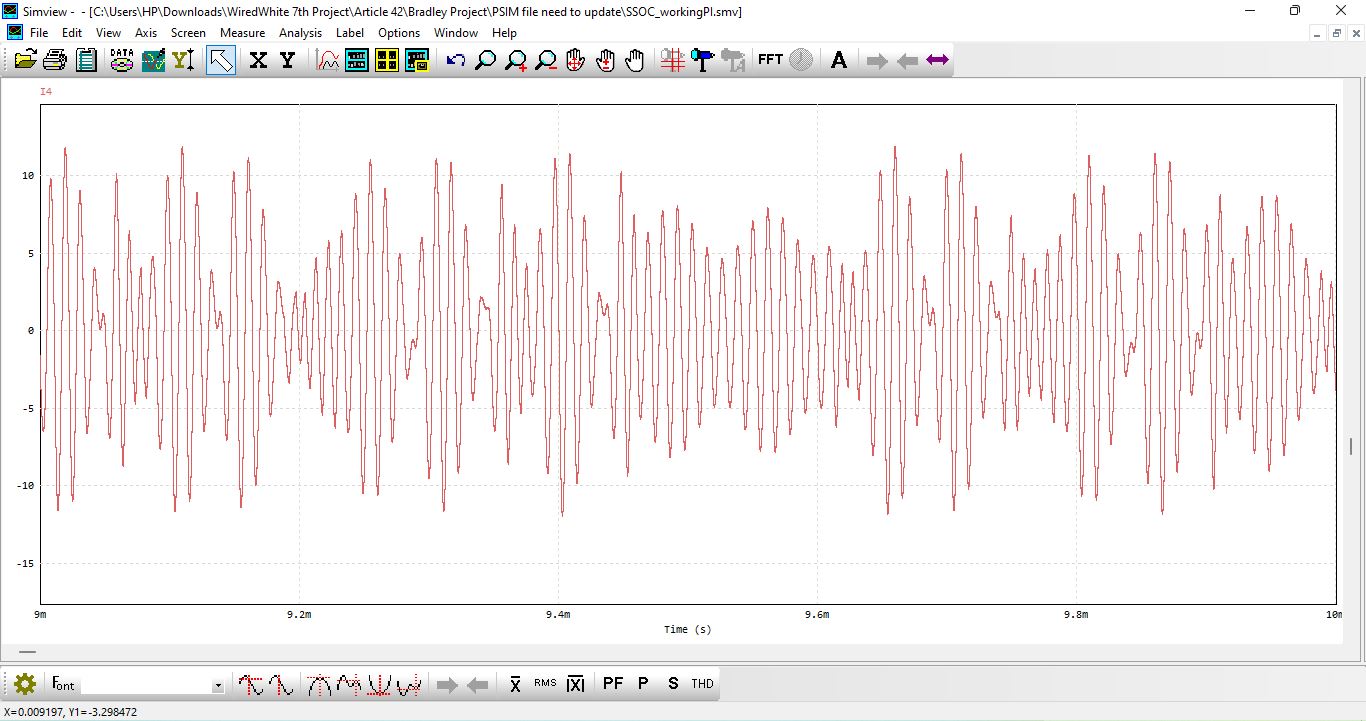
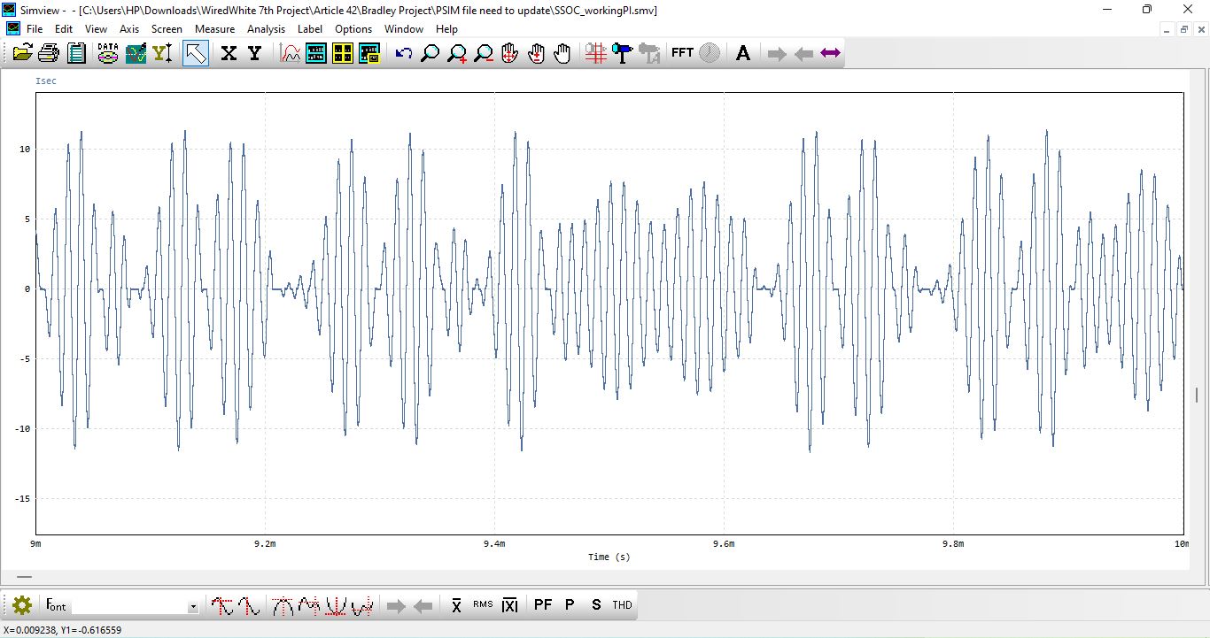
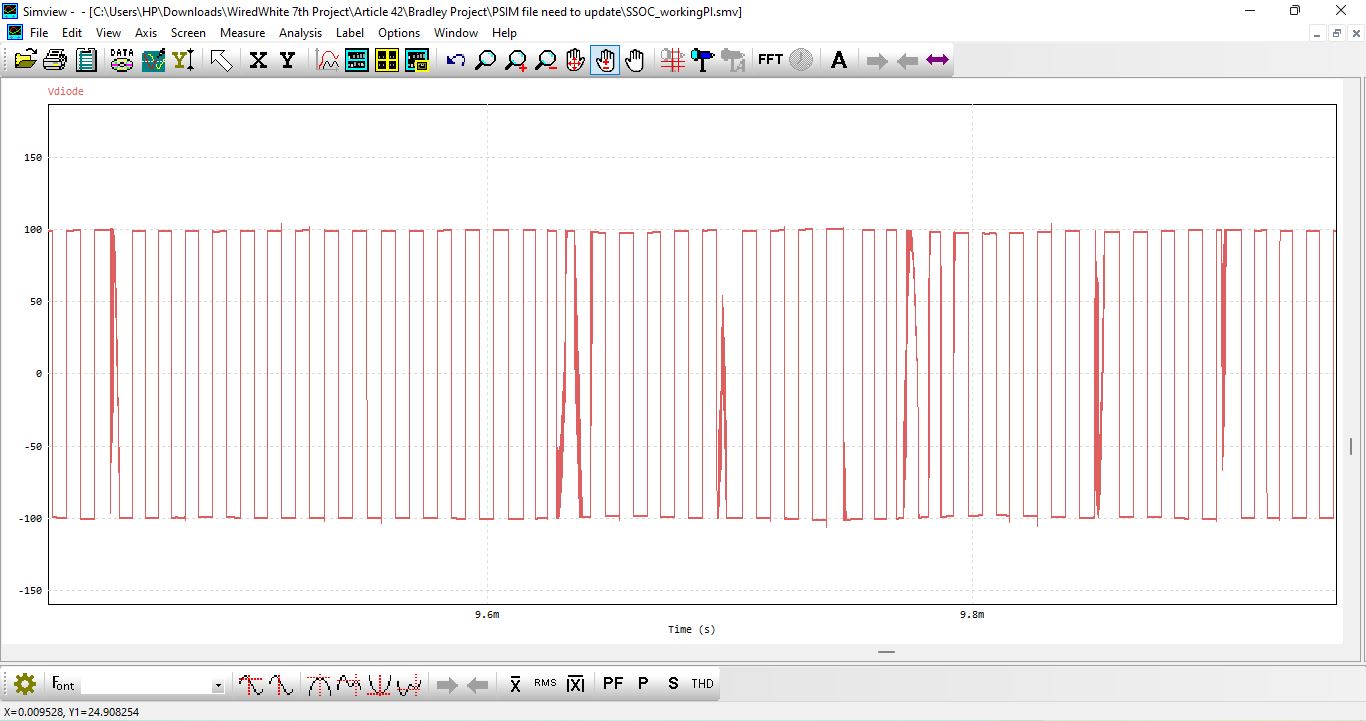
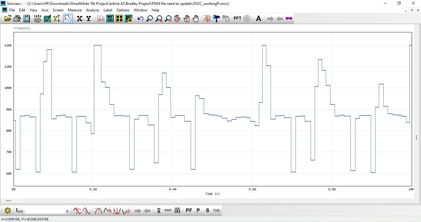
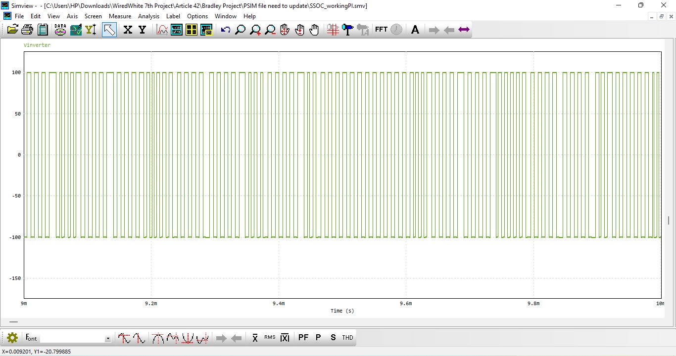
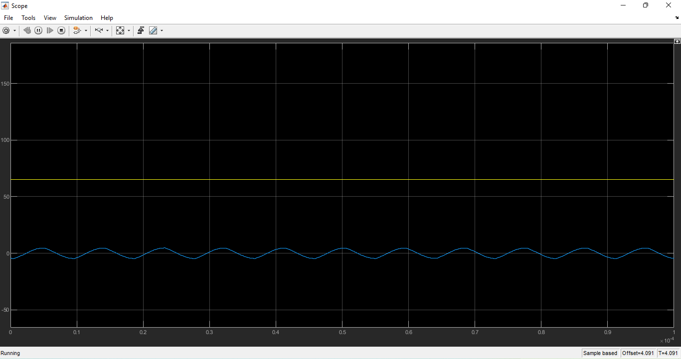
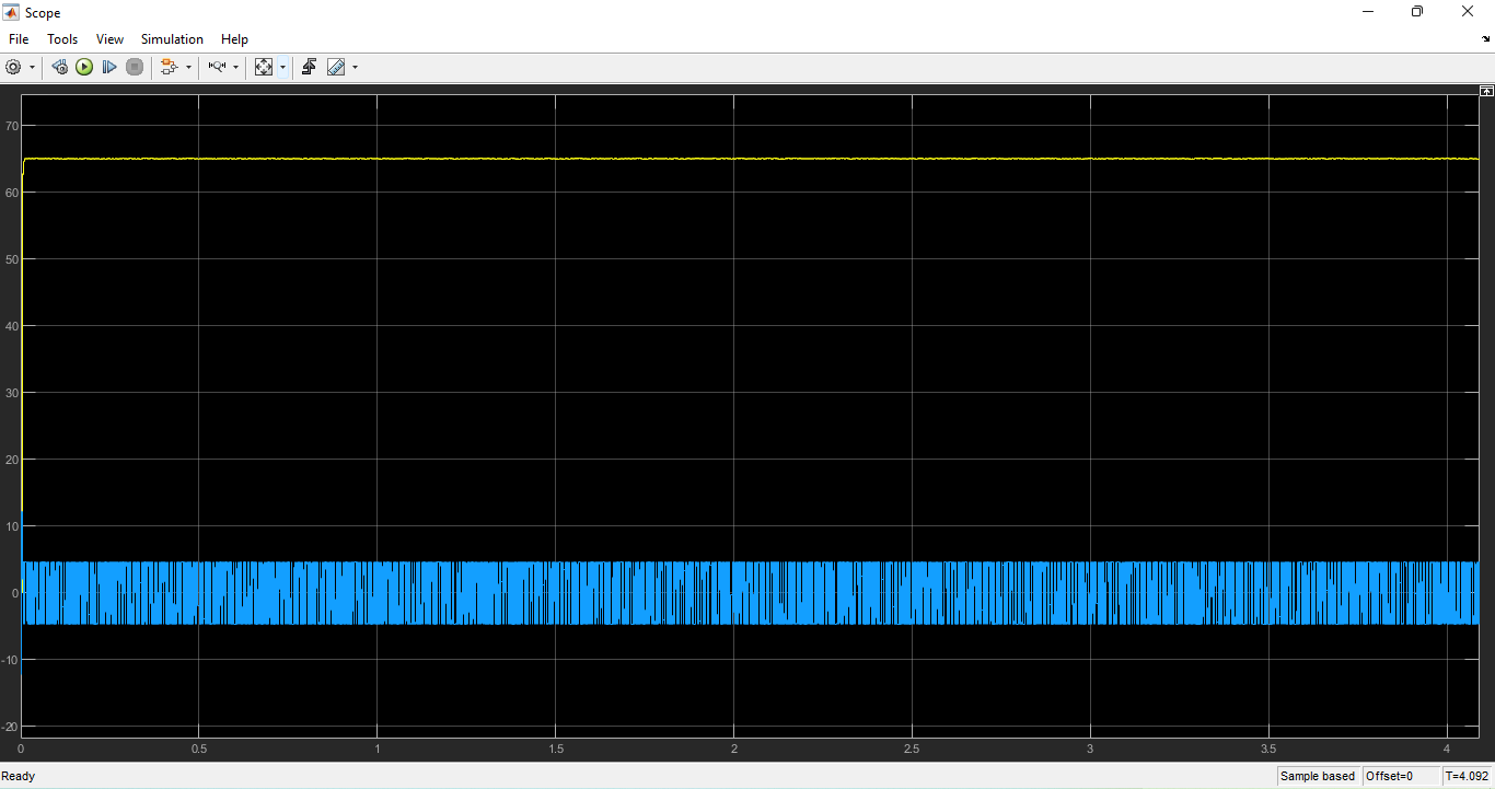
The simulation results demonstrated stable output voltage regulation at the set reference value, even under varying load resistance scenarios. When the load was changed, the ADC feedback loop detected the variation, and the PI controller adjusted the inverter’s switching frequency to restore the voltage to its target value. This dynamic adjustment ensured that the system maintained Zero Voltage Switching (ZVS), reducing switching losses and improving efficiency. In addition, waveform analysis confirmed proper phase alignment between voltage and current in the resonant tank, indicating minimal reactive power and high power transfer efficiency. The rectified DC output was free from excessive ripples, owing to appropriate filter capacitor selection.


You can download the Project files here: Download files now. (You must be logged in).
Further analysis was conducted to evaluate the system’s transient response. Step changes in the load were introduced to measure the controller’s response time and voltage overshoot. The PI-controlled frequency modulation proved effective, with minimal overshoot and quick settling times. The simulation also included efficiency analysis at different coupling coefficients to assess the system’s tolerance to coil misalignment. Results showed that while efficiency decreases slightly with reduced coupling, the voltage regulation mechanism still maintained the output within acceptable limits. These findings confirm that the proposed WPT design not only meets the operational requirements but also offers robustness and adaptability, making it suitable for practical wireless charging applications.
Conclusion
The designed and simulated Wireless Power Transfer (WPT) system successfully demonstrated efficient, contactless energy transfer using a resonant inductive coupling approach. The SS-compensated topology, operating at 85 kHz, provided high power transfer efficiency while maintaining stable output voltage under varying load conditions. The integration of a PI controller with frequency modulation proved highly effective for voltage regulation, ensuring the system could dynamically adapt to changes in load and coupling conditions without compromising performance. The use of Zero Voltage Switching (ZVS) further reduced switching losses, improved thermal performance, and enhanced overall system reliability.
Simulation results confirmed that the proposed design achieved minimal voltage ripple, quick transient response, and consistent performance across different load scenarios. The ability of the system to maintain efficiency even with reduced coupling coefficients highlighted its robustness to coil misalignment—a critical factor for practical applications such as wireless charging of electric vehicles, consumer electronics, and medical devices. The accurate phase alignment between voltage and current in the resonant tank minimized reactive power, contributing to optimal power delivery.
The methodology adopted ensured a balance between theoretical design, simulation accuracy, and practical feasibility. Component selection and parameter tuning were carried out with careful consideration of real-world constraints, allowing the system to be readily implemented in hardware with minimal modifications. The results validated the effectiveness of resonant inductive coupling combined with closed-loop control for achieving reliable wireless energy transfer.
Overall, this work not only demonstrated the fundamental principles of WPT but also provided a design framework that can be extended to higher power levels and different application domains. Future improvements could include the integration of advanced control algorithms such as adaptive or model predictive control for enhanced performance, as well as the exploration of multi-coil systems for greater spatial flexibility. The outcomes of this study indicate that the proposed WPT system is a promising solution for efficient, safe, and convenient power delivery in the rapidly growing field of wireless energy technologies.
References
- Kurs, A., et al., ‘Wireless power transfer via strongly coupled magnetic resonances,’ Science, vol. 317, no. 5834, pp. 83-86, 2007.
- Sample, A.P., et al., ‘Design of a loosely coupled planar wireless power system for multiple receivers,’ IEEE Trans. Ind. Electron., vol. 60, no. 7, pp. 2602-2612, 2013.
- Covic, G.A., et al., ‘Inductive power transfer,’ Proc. IEEE, vol. 101, no. 6, pp. 1276-1289, 2013.
- Li, S., Mi, C.C., ‘Wireless power transfer for electric vehicle applications,’ IEEE J. Emerg. Sel. Topics Power Electron., vol. 3, no. 1, pp. 4-17, 2015.
- Texas Instruments, ‘TIDU737 Reference Guide,’ 2015.
- Erickson, R.W., Maksimović, D., ‘Fundamentals of Power Electronics,’ Springer, 2001.
- Kazimierczuk, M.K., ‘Resonant Power Converters,’ John Wiley & Sons, 2011.
- Huang, L., et al., ‘A phase-shift-controlled resonant inverter for wireless power transfer,’ IEEE Trans. Power Electron., vol. 29, no. 8, pp. 4046-4057, 2014.
- Park, C., et al., ‘A 6.78 MHz wireless power transfer system with power factor correction,’ IEEE Trans. Power Electron., vol. 30, no. 11, pp. 6442-6450, 2015.
- Sokal, N.O., Sokal, A.D., ‘Class E – A new class of high-efficiency tuned single-ended switching power amplifiers,’ IEEE J. Solid-State Circuits, vol. 10, no. 3, pp. 168-176, 1975.
- Boys, J.T., Covic, G.A., ‘The inductive power transfer story at The University of Auckland,’ IEEE Circuits and Systems Magazine, vol. 15, no. 2, pp. 6-27, 2015.
- Villa, J.L., et al., ‘High-misalignment tolerant compensation topology for ICPT systems,’ IEEE Trans. Ind. Electron., vol. 59, no. 2, pp. 945-951, 2011.
- Choi, S.Y., et al., ‘Advances in wireless power transfer systems for roadway-powered electric vehicles,’ IEEE J. Emerg. Sel. Topics Power Electron., vol. 3, no. 1, pp. 18-36, 2015.
- Lu, F., et al., ‘Dynamic charging of electric vehicles by wireless power transfer,’ IEEE Trans. Ind. Electron., vol. 64, no. 7, pp. 6540-6547, 2017.
- Zhang, W., et al., ‘Frequency splitting analysis of two-coil resonant wireless power transfer,’ IEEE Trans. Ind. Electron., vol. 29, no. 2, pp. 936-945, 2014.
You can download the Project files here: Download files now. (You must be logged in).


Responses