

Stress Concentration and How Mesh Density Affects Results
Introduction
In Finite Element Analysis (FEA), accuracy doesn’t just depend on the material properties or boundary conditions, it depends heavily on mesh quality and density. One of the most common sources of error in simulations is stress concentration, especially when the mesh around critical areas is too coarse.
Understanding where and why stress concentrates, and how mesh refinement affects the results, is crucial for producing reliable simulations in SolidWorks or any FEA software.
What Is Stress Concentration?
Stress concentration occurs when stress in a material is higher in a localized region than in the surrounding area.
This usually happens near geometric discontinuities such as:
- Sharp corners
- Holes or cutouts
- Notches
- Fillets
- Sudden changes in cross-section
When a structure is loaded, these features cause a local disturbance in the stress flow, amplifying the stress far beyond the nominal value.
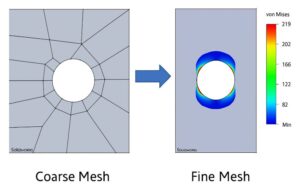
For example, a simple flat plate with a circular hole under tension will show stresses near the hole edge several times higher than the average stress across the plate.
Why Stress Concentration Matters
Ignoring stress concentrations can lead to unsafe designs, even when the overall stresses seem acceptable.
For example:
- A shaft with a keyway may fail prematurely if local stresses are underestimated.
- A bracket with a sharp fillet may crack in fatigue testing despite passing static analysis.
In real-world applications, engineers often reduce stress concentrations by adding fillets, rounds, or blending transitions, but in simulation, the accuracy of the result still depends on your mesh.
How Mesh Density Influences Stress Results
The mesh divides your geometry into small finite elements. Each element approximates the displacement, strain, and stress within its region.
However, FEA can only capture sharp stress gradients if the mesh is fine enough around critical zones.
- Coarse mesh: Stress is averaged over larger elements → smooth but inaccurate results
- Fine mesh: Captures sharp gradients near holes, fillets, or notches → higher accuracy, especially for peak stresses.
In simple terms:
The more refined your mesh near the stress raiser, the closer your results will be to reality.
SolidWorks Experiment: Stress Concentration and How Mesh Density Affects FEA Results
You can download the Project files here: Download files now (You must be logged in).
Finite Element Analysis (FEA) results are only as reliable as the mesh used to generate them.
One of the most common mistakes beginners make in SolidWorks Simulation is trusting stress values without questioning mesh quality, especially in regions with high stress gradients.
In this example, the same part, material, boundary conditions, and loads were used, only the mesh strategy was changed.
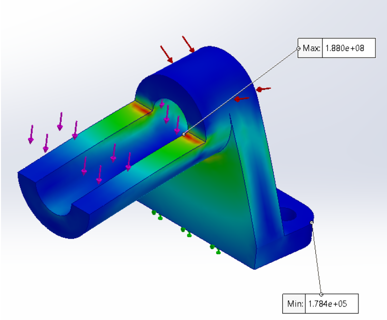
Geometry and Boundary Conditions
The analyzed part contains:
- A curved transition between a cantilevered arm and a vertical support
- Sharp curvature changes and fillets
- Fixed constraints at the base
- Distributed loads applied to the upper surfaces
This geometry naturally introduces stress concentrations, especially at:
- Fillet roots
- Internal corners
- Load transfer regions
These are precisely the areas where mesh quality matters most.
You can download the Project files here: Download files now (You must be logged in).
Case 1: Coarse Mesh (Uniform Large Elements)
In the first study, a coarse, uniform mesh was applied across the entire model.
Characteristics
- Large elements
- Minimal refinement
- Fast solution time
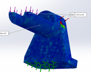
Observed Results
- Stress contours appear overly smooth
- Peak stress values are lower
- Stress gradients are poorly resolved
- Critical areas blend into surrounding regions

Interpretation
With a coarse mesh:
- The solver averages stress over large elements
- Local stress peaks are numerically smeared
- Stress concentration effects are underestimated
This does not mean the part is safer, it means the mesh is not resolving the physics correctly.
You can download the Project files here: Download files now (You must be logged in).
Case 2: Refined Mesh in High-Stress Regions
In the second study, local mesh refinement was applied:
- Smaller elements at fillets and curvature transitions
- Gradual mesh transition to avoid distortion
- Coarser mesh retained in low-stress regions
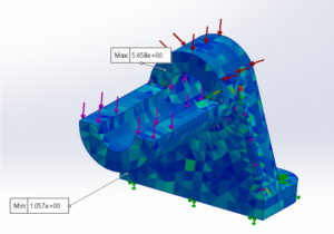
Observed Results
- Stress contours become sharper and more localized
- Peak stress values increase
- Stress concentration zones are clearly visible
- Load paths are easier to interpret
Interpretation
This mesh better captures:
- High stress gradients
- Local bending effects
- Geometric stress concentration behavior
The higher maximum stress does not indicate an error, it indicates better resolution of the real stress field.
Why the Results Are Different
Stress is calculated at element integration points and extrapolated to nodes.
When elements are too large:
- High gradients cannot be captured
- Maximum stress values are artificially reduced
When elements are refined:
- Stress gradients are resolved
- Local peaks emerge
- Results converge toward the true solution
This is why mesh convergence, not a single stress plot, determines accuracy.
You can download the Project files here: Download files now (You must be logged in).
How to Refine a Mesh in SolidWorks Simulation (Step-by-Step + Aspect Ratio Explained)
In SolidWorks Simulation, mesh quality is one of the most important factors affecting stress results.
High stresses almost never appear randomly, they usually occur near holes, fillets, sharp corners, thin ribs, load locations, fixtures, and contact regions. These are exactly the areas where poor meshing can create misleading results.
Instead of immediately making the entire model extremely fine (which increases solve time dramatically), follow a progressive refinement strategy:
- Start with a global mesh
- Improve curvature representation
- Refine only critical regions
- Check element quality especially aspect ratio
This workflow keeps analyses accurate and computationally efficient.
Let’s walk through it step by step.
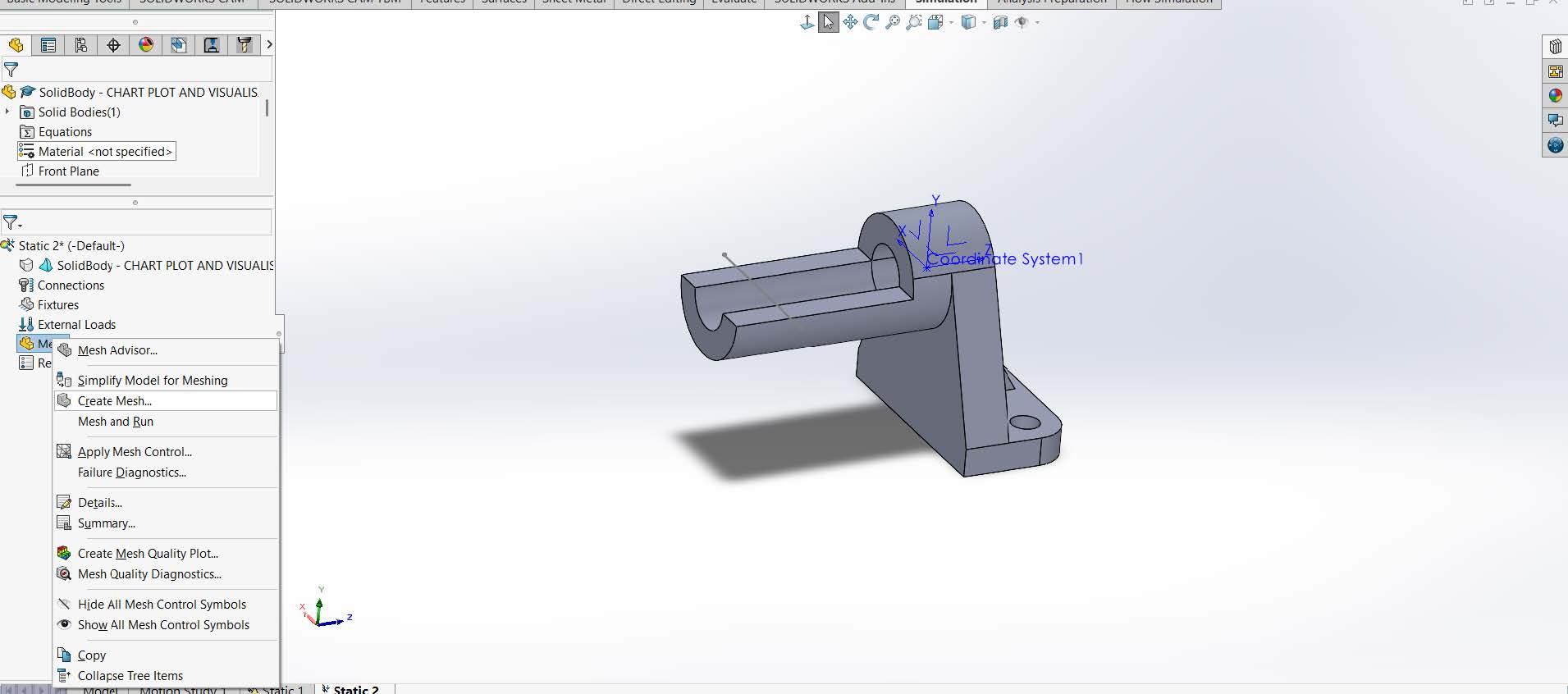
Step 1 — Run a Global Mesh First
Begin by creating a standard global mesh.
In the Simulation study tree, right-click Mesh and select Create Mesh. Leave local controls off for now and use default or slightly coarse settings.
A global mesh applies roughly the same element size throughout the model. This first run is not meant for final answers, it is only used to:
- locate high-stress regions
- see deformation patterns
- identify sensitive geometry
- spot unrealistic stress spikes
- understand load paths
After solving, inspect stress plots and note where the highest stresses appear. These zones are your prime candidates for refinement.
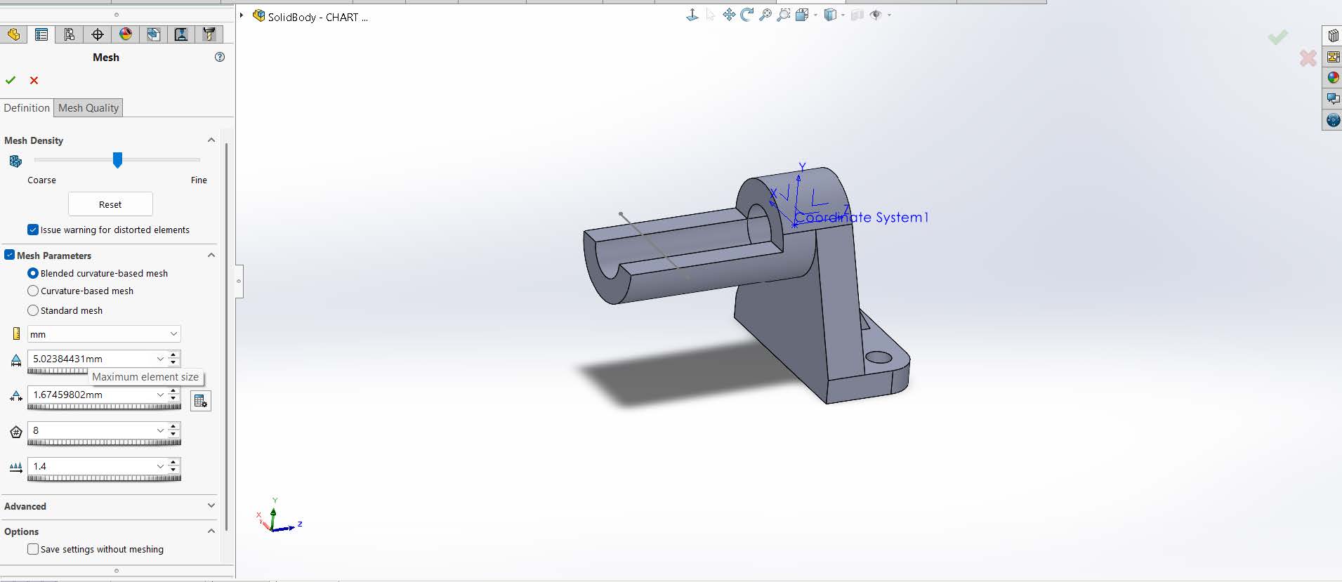
Step 2 — Enable Curvature-Based Meshing
Next, edit the mesh and turn on Curvature-based mesh.
This option automatically places smaller elements around curved surfaces and small radii, even if your global element size remains relatively large.
It is especially useful for:
- fillets and rounds
- holes and cylindrical faces
- complex surfaces
- thin curved features
Curvature-based meshing improves geometry representation and reduces artificial stress spikes caused by overly coarse elements.
The trade-off is increased element count and slightly longer solve times, but the accuracy gain is usually worth it.
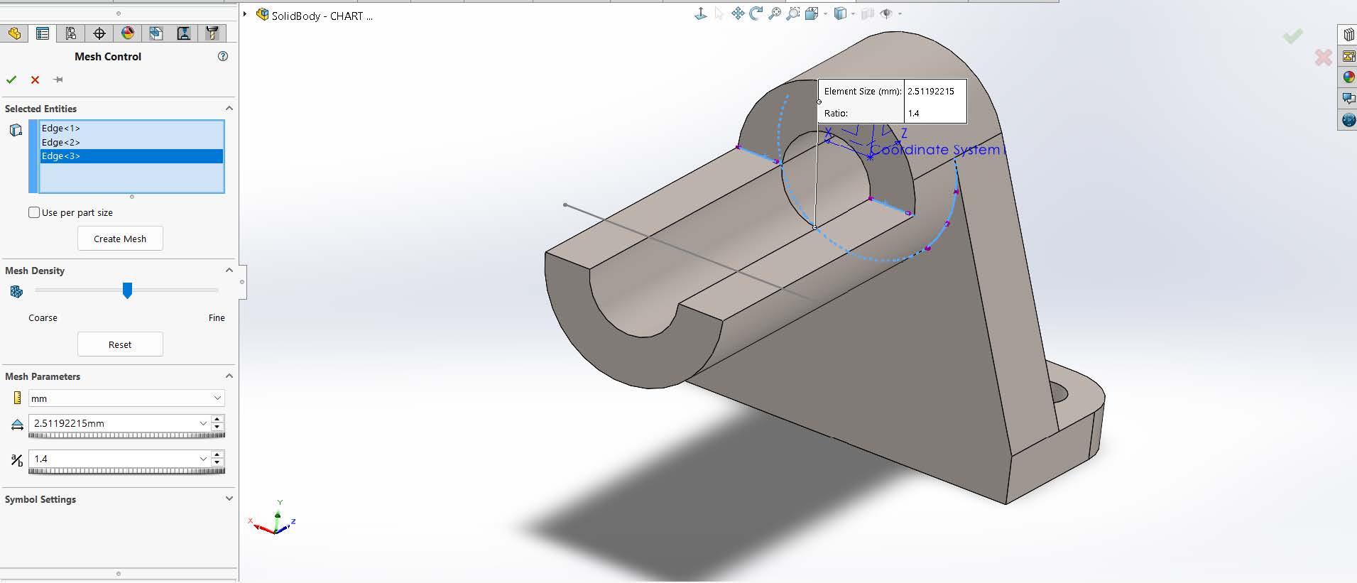
Step 3 — Apply Local Mesh Controls in Critical Areas
For the highest accuracy without exploding solve time, apply Mesh Controls.
Mesh controls allow you to define a smaller element size only on selected faces, edges, bodies, or components.
These should be applied where you expect:
- stress concentrations
- load transfer
- sharp corners
- contact interfaces
- bolt holes or slots
- thin ribs or webs
This targeted refinement is the most efficient approach: high resolution where it matters, coarse mesh elsewhere.
You can download the Project files here: Download files now (You must be logged in).
Why Mesh Quality Matters: Aspect Ratio Explained
Element size alone does not define mesh quality.
Aspect ratio is one of the most important quality indicators.
It describes the shape of individual finite elements:
Aspect ratio = longest element dimension ÷ shortest dimension
An ideal element has roughly equal dimensions in all directions, giving an aspect ratio close to 1.
When elements become long and skinny, the aspect ratio increases, and numerical accuracy begins to suffer.
How Poor Aspect Ratio Affects Results
Elements with very high aspect ratios can:
- distort stress predictions
- exaggerate peak stresses
- slow solver convergence
- introduce numerical noise
- cause instability in contact studies
That means even a very fine mesh can give unreliable results if element shapes are poor.
This is why experienced engineers always evaluate element quality, not just mesh density.
What Aspect Ratio Is Acceptable?
Typical industry guidelines:
- 1–3 → Excellent
- 3–10 → Generally acceptable
- 10–20 → Use caution
- Above 20 → Poor — should be corrected
Exact limits depend on study type and solver settings, but these ranges are good practical targets.
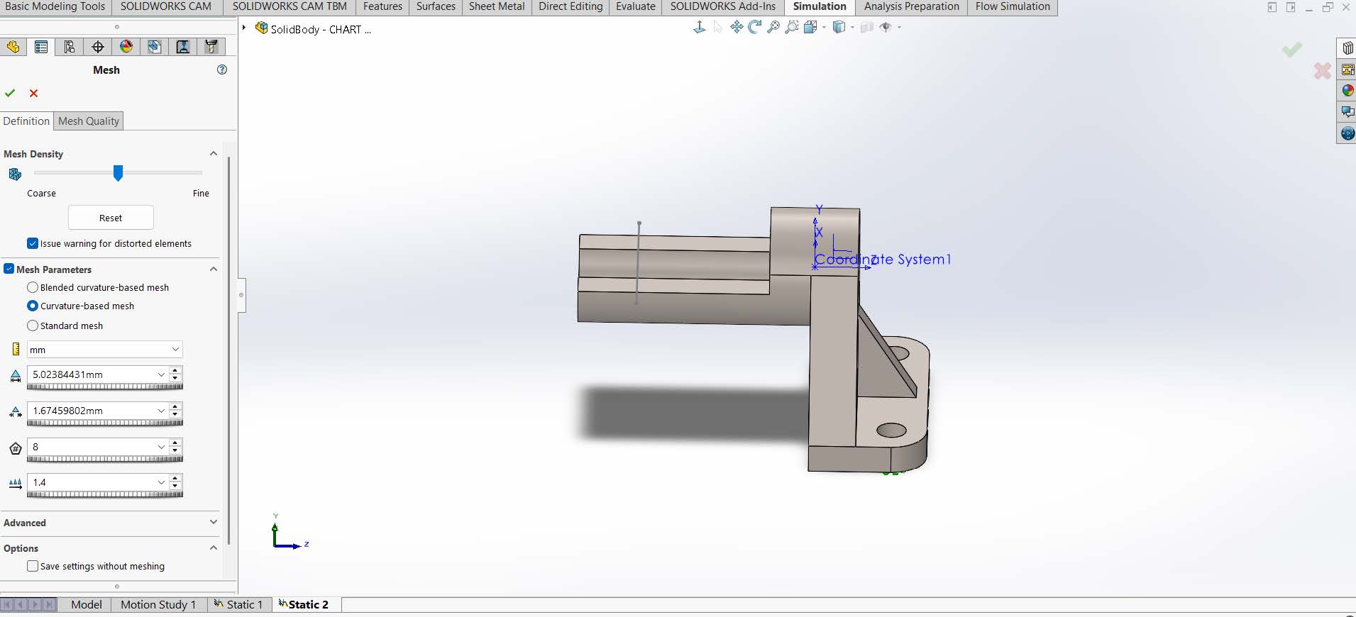
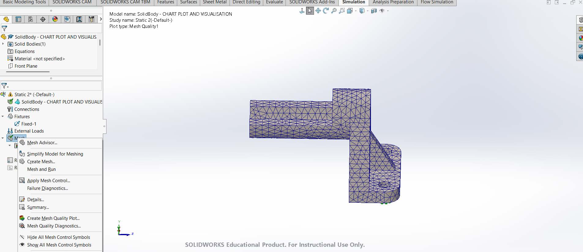
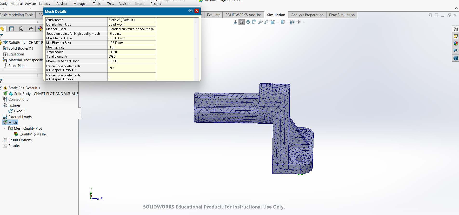
Where to Find Aspect Ratio in SolidWorks
After meshing:
- Right-click Mesh in the Simulation tree
- Select Quality Plot or Mesh Details
- Choose Aspect Ratio
- Display the plot
Problematic elements will be highlighted so you can immediately see where improvements are needed.
How to Fix High Aspect Ratio Elements
If poor-quality elements appear, try:
- adding local mesh controls
- reducing element size in that region
- enabling curvature-based meshing
- splitting large faces with sketch features
- simplifying tiny sliver geometry
- suppressing unnecessary small fillets
- cleaning imported geometry
Often the best fix is geometry cleanup, not brute-force refinement everywhere.
Final Step — Perform a Mesh Convergence Check
Even with good element quality, never rely on a single mesh.
Refine the mesh gradually, rerun the study, and track peak stress values.
When stresses stop changing significantly between refinements, the solution is considered mesh-converged, and only then should results be used for design decisions.
Summary: Professional Mesh Refinement Workflow
A solid SolidWorks Simulation workflow looks like this:
- run a coarse global mesh
- enable curvature-based meshing
- apply local mesh controls
- inspect aspect ratio
- fix poor elements
- check convergence
Follow this sequence and your FEA results will be far more reliable without wasting hours on unnecessarily dense meshes.
Conclusion
- Stress concentration zones always require mesh refinement
- Fillets
- Holes
- Sharp transitions
- Load application areas
- Lower stress values do not mean safer designs
- They often indicate insufficient mesh resolution
- FEA is not about getting a number
- It’s about understanding where and why stresses occur
- Mesh refinement should be targeted
- Fine where stress gradients are high
- Coarse where stress is uniform
Practical Recommendation
Before trusting any FEA result:
- Refine the mesh in critical regions
- Compare stress trends, not just maximum values
- Check whether results stabilize with refinement
If stress values continue to change significantly with mesh refinement, the solution has not yet converged.
Final Note
This example clearly demonstrates why mesh density is not a cosmetic setting, it directly controls the physical accuracy of your simulation.
Understanding this difference is one of the key steps from running simulations to engineering with simulations.
You can download the Project files here: Download files now (You must be logged in).
Conclusion
Mesh density isn’t just a technical setting, it’s a critical design decision that determines the trustworthiness of your simulation.
Understanding how stress concentration and mesh refinement interact is what separates simulation users from simulation engineers.
Next time you run an FEA study in SolidWorks, don’t just hit “run.”
Refine. Compare. Converge.
That’s how you turn your simulation into real engineering insight.
If you want to master static analysis and mesh refinement in SolidWorks, take a look at this course: SOLIDWORKS: Introduction To Finite Element Analysis (FEA) | WiredWhite


Responses