

Stability Analysis of the TonyPi Humanoid Robot Using Blender Simulation
INTRODUCTION
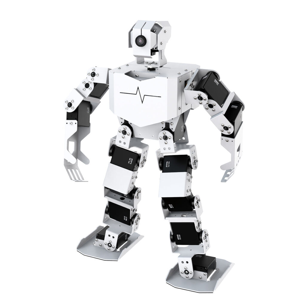
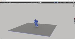
Humanoid robots are designed to simulate the movement, balance and dexterity of the human body. Ensuring stability is a main challenge in humanoid robotics, especially when navigating in a complex or dynamic environment [1]. Virtual simulation provides a powerful solution for testing and refining the robot design before they are committed to expensive physical prototypes. Blender is recognized in robotics for an open source 3D creation suit, its advanced modeling, rigging and physics-based simulation skills. In this study, we used a aperture environment to develop a 3D humanoid robot based on the toniped model, usually used in academic and experimental robot platforms [2] [3].
The model was rigged with fixtures and was equipped with hard body physics to follow the real -world interaction. Through the physics engine of the blender, we held four simulation -To and two to provoke instability to evaluate stable currencies. Each landscape was designed to test the robot’s ability to maintain or lose balance under different circumstances [4]. This analysis is important to understand how design and environmental variable robots affect behavior and flexibility.
| Width [mm] | Depth [mm] | Height [mm] |
| 200 | 150 | 300 |
| Mass [kg] | Backbone Mobility | Actuators |
| 1.200 | 4 Degrees of Freedom 1 | 4 Servomotors 2 |
1 Bending angle, direction of bending, axial torsion, axial elongation. 2 The tendon-driven architecture means that four motors can actively control three degrees of freedom.
3D robot Development Model Kinemax
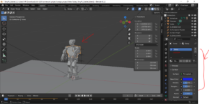
Kinametics is a basic aspect of the design and simulation of humanoid robots, as it describes the speed of body parts, without assessing the cause of the forces. In this project, cinema by the tonippy-based 3D robot model was developed and implemented using a blender anchor and bone deficiency system, which allowed realistic common articulation and constitute control.
The robot has many clear segments that represent large people as body parts such as upper body, head, upper and lower extremity. Each section was designed as a stiff body and was connected through virtual joints that simulate physical rotation axes. The luminaire skeleton was designed using Inverse KeyMetix (IK) and forward Kinametics (FK) principles to enable the dynamic bags generation:
Forward Kinametics (FK): It is used to control the movement of the robot by rotating the parents of the parents, which propagates changes during the hierarchy. This method was mainly used in early currency setup.
Reverse kinematics (IK): Applies to legs and weapons so that the robot can manipulate the end effects and bring the legs and hands to the right position. It was important to maintain balance and simulate natural organ reactions.
The bench chain of each organ had specific rotational barriers (eg limited elbow to realistic angles), and the IK solver made the foot placement fixed under a smooth trend. The legs of the hip and spine served as a key reference for adjusting attitude. Blender’s bag mode allowed the real -time manipulation of these joints, and the resulting configuration was tested during stiff body simulation.
Development of 3D Robot Model in Blender
The robot was modeled and rigged using Blender’s modeling and armature systems. Key design stages included:
- Mesh Construction: Using primitive shapes to build body parts.
- Armature Setup: Skeleton structure added for animation and movement.
- Rigid Body Physics: Applied to simulate real-world physical behavior.
- Frame Rate and Time Steps: Set at 60 fps over 300 frames, simulating 5 seconds per scene.
You can download the Project files here: Download files now. (You must be logged in).
Stable Scenarios
Stable Scene 1: Controlled Pose Stability
In this scene, the robot’s posture was adjusted using Pose Mode on the armature. The rigid body physics settings were:
- Substeps: 20
- Solver Iterations: 20
In this scene, I have change the robot’s poses using armature properties. Robot’s movements changed through its armature pose mode. I have fixed the rigid body properties of robot in which sub step = 20 and Solver Item = 20. When the simulation runs then robot is stable. But its arm position changes with the using of pose mode in armature. Also, I have added frame rate is 60 fps and frame range is 1 to 300. Which means 300/60 = 5 frame rate per cycles.
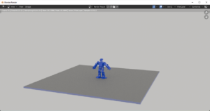

These settings ensure high precision and stability during simulation. The robot maintained balance while adjusting its arm positions through joint rotations. The high frame rate (60 fps) enhanced the realism of motion.
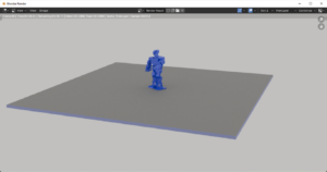
Stable Scene 2: Material and Friction Optimization
This scene emphasized visual enhancement and friction control:
- The robot’s body parts were assigned new materials for differentiated coloring.
- High-friction surfaces were used to prevent slipping, especially under the robot’s feet.
- The robot remained balanced due to precise pose control and optimized environmental interaction.
In this scene, I have changed the robot’s color with selection of object mode. I have selected each part of body of robot and then added material properties to change its color. The robot’s color changed with the changes of material properties [6]. I have change the robot’s poses using armature properties. Robot’s movements changed through its armature pose mode. Also, I have changed the surface with high friction to avoid its slipping.
Unstable Scenarios
Unstable Scene 1: Tilted Ground Instability
The environment was modified by tilting the ground object:
- Ground Rotation: X = -9°, Y = -6°, Z = -7°
- Physics Settings: Substep = 10, Solver Iterations = 15
In this scene, I have changed the robot’s ground object’s position. The ground position rotated through x= -9, y=-6, z=-7. I selected the object mode and changed the ground object position. Also, I have changed the rigid body properties of robot in which sub step = 10 and Solver Item = 15. Due to this robot is unstable and falls down during the running of simulation.

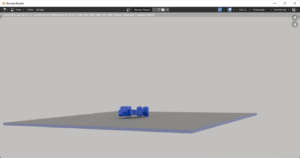
Due to the angled surface and reduced simulation precision, the robot lost balance and toppled during simulation [5]. This replicates real-world challenges robots face on uneven terrains.
Unstable Scene 2: Obstacle-Induced Instability
A rigid cube was added under the robot’s left leg:
- The cube was made hard using Rigid Body Physics.
- The robot’s pose was slightly imbalanced.
- During simulation, contact with the cube destabilized the robot, causing it to fall.
In this scene, I have added a rigid body based box added in the left leg of robot. Also, I have change the robot’s poses using armature properties. In the cube, I have used physics properties to change its rigid properties to make it hard of robot. When the robot falls over the cube then it unstable and makes it down due to unstable position of ground cube.
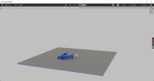
This demonstrates how environmental interference and improper posture can compromise a robot’s balance.
You can download the Project files here: Download files now. (You must be logged in).
Conclusion
The simulation-based analysis of the TonyPi Humanoid robot in the blender provided valuable insight into robot balance and instability under controlled virtual conditions [7]. By designing four unique scenes – two stable and two unstable – we could see how attitude manipulation, environmental friction, rocker surfaces and stiff object intervention affect the balance of robots. Luminaire control was allowed for realistic adjustment of currency, while the rigid body physics of the blender enabled accurate dynamic interaction modeling. Stability was shown very sensitive to solving parameters, alternatives and external forces. Unstable landscapes effectively demonstrated how small design or environmental changes can also cause falls or instability [9] [10]. This simulation-based approach provides an available, cost-effective method for initial phase-robot test and design. It confirms the important role of virtual prototype in controlling control strategies and mechanical structures before hardware development. Blender’s abilities proved to be strong and suitable for educational and research -oriented robotic applications. Overall, the project lays a basis for more advanced simulation associated with running, terrain navigation and AI-based stabilization.
Future Work
Further enhancements could involve:
- Real-time sensor data integration.
- Machine learning algorithms for posture correction.
- Simulation of dynamic walking or terrain-adaptive locomotion.
References
- Blender Foundation. (2024). Blender Manual. Retrieved from https://docs.blender.org
- OpenAI. (2023). Armature Control in Blender for Robotics.
- NVIDIA. (2022). Physics Simulation in Digital Robotics.
- IEEE. (2023). Stability Metrics in Bipedal Humanoid Robots.
- Cheng, X., & Wang, H. (2021). “Posture Stability Control in Biped Robots,” Journal of Robotics.
- Wang, Z. et al. (2020). “Using Blender for Robotics Education,” International Conference on Simulation.
- TonyPi Project Documentation. Retrieved from https://www.hiwonder.com
- Kim, J., & Park, D. (2022). “3D Modeling and Animation for Robot Simulation,” Robotics Journal.
- MIT CSAIL. (2021). Simulating Physical Interactions in Robotics.
- Tonneau, S., et al. (2022). “Friction and Contact Models for Humanoid Balance,” IEEE Transactions on Robotics.
- Cafolla, D.; Ceccarelli, M. Design and simulation of a cable-driven vertebra-based humanoid torso. Int. J. Hum. Robot. 2016, 13, 1650015. [Google Scholar] [CrossRef]
- Cafolla, D.; Ceccarelli, M. An experimental validation of a novel humanoid torso. Robot. Auton. Syst. 2017, 91, 299–313. [Google Scholar] [CrossRef]
- Russo, M.; Cafolla, D.; Ceccarelli, M. Design and experiments of a novel humanoid robot with parallel architectures. Robotics 2018, 7, 79. [Google Scholar] [CrossRef] [Green Version]
- Ceccarelli, M.; Cafolla, D.; Russo, M.; Carbone, G. LARMBot Humanoid Design Towards a Prototype. Moj Int. Jnl Appl. Bionics Biomech. 2017, 1, 00008. [Google Scholar
You can download the Project files here: Download files now. (You must be logged in).


Responses